oil change SSANGYONG RODIUS 2012 Service Manual
[x] Cancel search | Manufacturer: SSANGYONG, Model Year: 2012, Model line: RODIUS, Model: SSANGYONG RODIUS 2012Pages: 715, PDF Size: 79.36 MB
Page 141 of 715

02-50000-00
1990-00 Rear Engine Mount
- Changed design
3240-01 Transfer Case (T/C)
- Changed TOD type T/C to Part-Time T/C
4411-01 Front Suspension
- Changed components
Coil spring
assemblyUpper arm
assembly
Stabilizer bar
assembly
Lower arm assembly
Stabilizer bar
assembly
Knuckle assembly
Upper arm
assembly
Lower arm assembly
Shock absorber
assembly
Knuckle
assembly
Page 149 of 715

01-70000-00
1) Service Interval
DescriptionDaily
inspectionWeekly
inspectionService interval
Engine oil & oil
filterInspection - EU Change every 20,000 km or 12
months (The service interval should
be shortened under severe
conditions)
General Change every 15,000 km or 12
months (The service interval should
be shortened under severe
conditions)
Coolant Inspection - Change every 200,000 km or 5 years
Air cleaner
element- Inspection Diesel EU Change every 20,000 km
(The service interval should
be shortened under severe
conditions)
General Change every 15,000 km
(The service interval should
be shortened under severe
conditions)
Gasoline Clean every 15,000 km, replace every
60,000 km (The service interval should
be shortened under severe
conditions)
Fuel filter - - EU Change every 40,000 km (Draining
water from fuel filter: whenever
replacing the engine oil)
General Change every 45,000 km (Draining
water from fuel filter: whenever
replacing the engine oil)
Page 224 of 715

03-20
Water
separator
(2) Di engine and its expected problems and remedies can be caused by
water in fuel
System supplement against paraffin separation ▶
In case of Diesel fuel, paraffin, one of the elements, can be separated from fuel during winter and
then can stick on the fuel filter blocking fuel flow and causing difficult starting finally. Oil
companies supply summer fuel and winter fuel by differentiating mixing ratio of kerosene and
other elements by region and season. However, above phenomenon can be happened if stations
have poor facilities or sell improper fuel for the season. In case of DI engine, purity of fuel is very
important factor to keep internal preciseness of HP pump and injector.
Accordingly, more dense mesh than conventional fuel filter is used. To prevent fuel filter internal
clogging due to paraffin separation, SYMC is using fuel line that high pressure and temperature
fuel injected by injector returns through fuel filter to have an effect of built-in heater (see fuel
system).
System supplement and remedy against water in fuel ▶
As mentioned above, some gas stations supply fuel with excessive than specified water. In the
conventional IDI engine, excessive water in the fuel only causes dropping engine power or engine
hunting. However, fuel system in the DI engine consists of precise components so water in the
fuel can cause malfunctions of HP pump due to poor lubrication of pump caused by poor coating
film during high speed pumping and bacterization (under long period parking). To prevent
problems can be caused by excessive water in fuel, water separator is installed inside of fuel
filter. When fuel is passing filter, water that has relatively bigger specific gravity is accumulated on
the bottom of the filter.
Water drain from water separator ▶
If water in the separator on the fuel filter exceeds a certain level, it will be supplied to HP pump
with fuel, so the engine ECU turns on warning lamp on the meter cluster and buzzer if water level
is higher than a certain level.
Due to engine layout, a customer cannot easily drain water from fuel filter directly, so if a
customer checks in to change engine oil, be sure to perform water drain from fuel filter.
To separate the water from the fuel filter,
remove the fuel filter assembly first.
Page 252 of 715

06-111914-01
3. TROUBLESHOOTING
The followings are cautions to take in handling defects of turbocharger, which must be fully aware
of.
1) Cautions
After stopping the engine, check whether the bolts on pipe connecting section are loose as
well as the connecting condition of vacuum port and modulator, which is connected to the
actuator.
During idling of the engine, check for leakage in the connecting section of pipe (hoses and
pipes, duct connections, after the turbocharger) by applying soap water. The leakage condition
in the engine block and turbine housing opening can be determined by the occurrence of
abnormal noise of exhaust.
By running the engine at idle speed, abnormal vibration and noise can be checked.
Immediately stop the engine when abnormal vibration and noise is detected and make
thorough inspection whether the turbocharger shaft wheel has any damages as well as
checking the condition of connections between pipes.
In case where the noise of engine is louder than usual, there is possibility of dampness in the
areas related with air cleaner and engine or engine block and turbocharger. And it could affect
the smooth supply of engine oil and discharge.
Check for damp condition in exhaust gas when there is sign of thermal discoloration or
discharge of carbon in connecting area of the duct.
When the engine rotates or in case where there is change in noise level, check for clogging of
air cleaner or air cleaner duct or if there is any significant amount of dust in the compressor
housing.
During the inspection of center housing, inspect inside of the housing by removing the oil drain
pipe to check for sludge generation and its attachment condition at shaft area or turbine side.
Inspect or replace the air cleaner when the compressor wheel is damaged by inflow of foreign
materials.
Inspect both side of the turbocharger wheel after removing inlet and outlet pipe of the
turbocharger. 1.
2.
3.
4.
5.
6.
7.
8.
9.
Page 264 of 715

07-31543-00
1. SPECIFICATION
The engine oil filter element should be changed at the same time with the engine oil.
Regularly check the engine oil level and add the engine oil if necessary.
Remember to check the engine oil level and shorten the cycle to replace the engine oil
under severe driving conditions. -
-
Severe Driving Condition
Frequent stop-and-go traffic, extended idling, short driving distance below 6 km, driving
distance below 16 km when the outside temperature remains below freezing
Driving in a hilly or mountainous terrain, sandy, or dusty area
High load driving such as trailer towing
Taxi, patrol service or delivery service (extended idling and excessive driving with low speed) -
-
-
-
Unit Specification
Oil pump Lubrication system Gear pump, forced circulation
Type Inscribed gear
Capacity 63 L at 4,000 rpm
Relief pressure5.8 bar ± 0.3 bar
Oil filter Type Full flow/Paper element
Engine oil Specified oil SAE 5W30 (approved by MB SHEET 229.51)
Capacity (L) Min.: 4.5 L
Max.: 6.0 L
Service
intervalEU Change every 20,000 km or 12 months
(The service interval should be shortened under
severe conditions)
General Change every 15,000 km or 12 months
(The service interval should be shortened under
severe conditions)
Oil injection nozzle Type Piston
Operating pressure 1.5bar
Closing pressure 1.0bar
Oil flow 4 L/min
Oil pressure switch Permissible pressure 10bar
Page 336 of 715

15-110000-00
2) ECU Control
(1) Function
a. ECU Function
ECU receives and analyzes signals from various sensors and then modifies those signals into
permissible voltage levels and analyzes to control respective actuators.
ECU microprocessor calculates injection period and injection timing proper for engine piston speed and
crankshaft angle based on input data and stored specific map to control the engine power and emission
gas.
Output signal of the ECU microprocessor drives pressure control valve to control the rail pressure and
activates injector solenoid valve to control the fuel injection period and injection timing; so controls
various actuators in response to engine changes. Auxiliary function of ECU has adopted to reduce
emission gas, improve fuel economy and enhance safety, comforts and conveniences. For example,
there are EGR, booster pressure control, autocruise (export only) and immobilizer and adopted CAN
communication to exchange data among electrical systems (automatic T/M and brake system) in the
vehicle fluently. And Scanner can be used to diagnose vehicle status and defectives.
<00760097008c00990088009b00900095008e0047009b008c00940097008c00990088009b009c0099008c0047009900880095008e008c00470096008d0047006c006a007c00470090009a0047009500960099009400880093009300a000470054005b005700
47009b009600470052005f005c00b6006a004700880095008b> protected from factors like oil,
water and electromagnetism and there should be no mechanical shocks.
To control the fuel volume precisely under repeated injections, high current should be applied instantly
so there is injector drive circuit in the ECU to generate necessary current during injector drive stages.
Current control circuit divides current applying time (injection time) into full-in-current-phase and hold-
current-phase and then the injectors should work very correctly under every working condition.
b. Control Function
Controls by operating stages
To make optimum combustion under every operating stage, ECU should calculate proper injection
volume in each stage by considering various factors.
Starting injection volume control
During initial starting, injecting fuel volume will be calculated by function of temperature and engine
cranking speed. Starting injection continues from when the ignition switch is turned to ignition
position to till the engine reaches to allowable minimum speed.
Driving mode control
If the vehicle runs normally, fuel injection volume will be calculated by accelerator pedal travel and
engine rpm and the drive map will be used to match the drivers inputs with optimum engine power. -
-
-
Page 568 of 715

03-113010-00
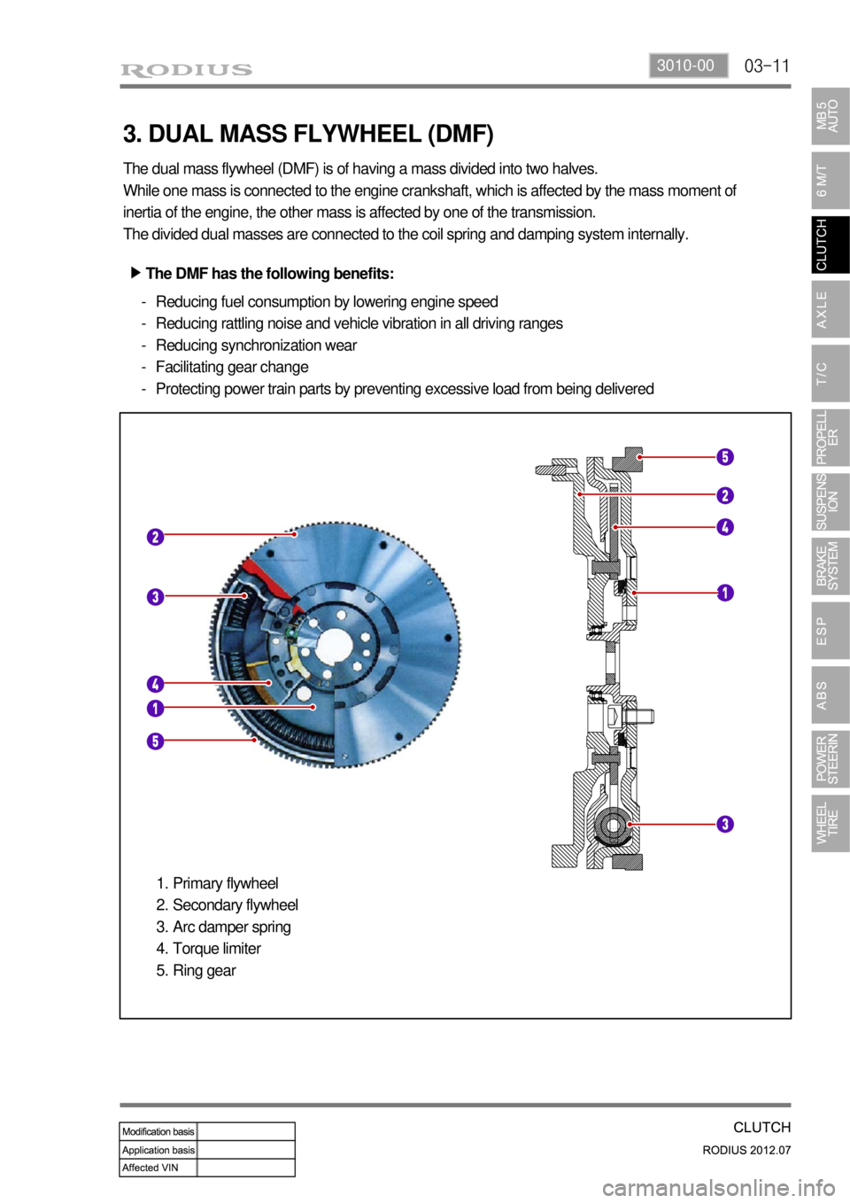
3. DUAL MASS FLYWHEEL (DMF)
The dual mass flywheel (DMF) is of having a mass divided into two halves.
While one mass is connected to the engine crankshaft, which is affected by the mass moment of
inertia of the engine, the other mass is affected by one of the transmission.
The divided dual masses are connected to the coil spring and damping system internally.
The DMF has the following benefits: ▶
Reducing fuel consumption by lowering engine speed
Reducing rattling noise and vehicle vibration in all driving ranges
Reducing synchronization wear
Facilitating gear change
Protecting power train parts by preventing excessive load from being delivered -
-
-
-
-
Primary flywheel
Secondary flywheel
Arc damper spring
Torque limiter
Ring gear 1.
2.
3.
4.
5.
Page 588 of 715

07-54411-01
Front Stabilizer Bar Assembly
To reduce the rolling effect of vehicle, the front stabilizer assembly has been changed.
Front Shock Absorber Assembly
To enhance the riding comfort, the coil spring rate and damping force have been changed.
Page 639 of 715

10-10
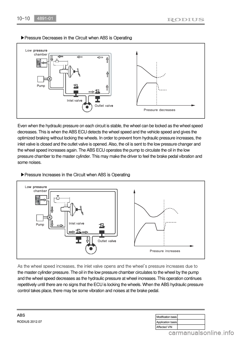
▶Pressure Decreases in the Circuit when ABS is Operating
Even when the hydraulic pressure on each circuit is stable, the wheel can be locked as the wheel speed
decreases. This is when the ABS ECU detects the wheel speed and the vehicle speed and gives the
optimized braking without locking the wheels. In order to prevent from hydraulic pressure increases, the
inlet valve is closed and the outlet valve is opened. Also, the oil is sent to the low pressure changer and
the wheel speed increases again. The ABS ECU operates the pump to circulate the oil in the low
pressure chamber to the master cylinder. This may make the driver to feel the brake pedal vibration and
some noises.
▶Pressure Increases in the Circuit when ABS is Operating
<0068009a0047009b008f008c0047009e008f008c008c00930047009a0097008c008c008b004700900095008a0099008c0088009a008c009a00530047009b008f008c0047009000950093008c009b0047009d00880093009d008c004700960097008c009500
9a004700880095008b0047009b008f008c0047009e008f008c>el’s pressure increases due to
the master cylinder pressure. The oil in the low pressure chamber circulates to the wheel by the pump
and the wheel speed decreases as the hydraulic pressure at wheel increases. This operation continues
repetitively until there are no signs that the ECU is locking the wheels. When the ABS hydraulic pressure
control takes place, there may be some vibration and noises at the brake pedal.
Page 646 of 715

11-8
Oil Level Check ▶
Check the fluid level on a level ground with the
engine turned off. The fluid level should be
between the MIN and MAX marks on the
reservoir cap gauge.
Place the vehicle on a level ground and start
the engine and let it run at idle speed.
Turn the steering wheel several times so that
the oil temperature reaches to normal
operating level (75~85˚C).
Place the steering wheel at straight ahead
direction.
Check the oil level in the power steering oil
reservoir. Adjust the oil level between MAX
and MIN. A.
B.
C.
D.
Oil Change ▶
If the difference between two measurements
is below 5 mm and the level is between MAX
and MIN level, it's normal. If it is over 5 mm,
bleed air from the system.
Open the power fluid reservoir cap and drain
the fluid completely with oil suction device.
To make it easy, turn the steering wheel to its
both ends several times.
Fill up the specified fluid into fluid reservoir
and bleed air from the steering system. A.
B.
Oil typeS-PSF3
Capacityapprox. 1.1ℓ
(including reservoir)
below 5
mm
Engine running Engine idling