timing SSANGYONG TURISMO 2013 User Guide
[x] Cancel search | Manufacturer: SSANGYONG, Model Year: 2013, Model line: TURISMO, Model: SSANGYONG TURISMO 2013Pages: 796, PDF Size: 78.99 MB
Page 345 of 796

15-170000-00
A fourth correction is made according to the pressure error.
This correction is used to reduce the injection timing advance when the pressure in the rail is higher
than the pressure demand.
A fifth correction is made according to the rate of EGR.
This correction is used to correct the injection timing advance as a function of the rate of exhaust
gas recirculation. -
-
When the EGR rate increases, the injection timing advance must in fact be increased in order to
compensate for the fall in termperature in the cylinder.
A. Main Flow Control
The main flow represents the amount of fuel injected into the cylinder during the main injection. The
pilot flow represents the amount of fuel injected during the pilot injection.
The total fuel injected during 1 cycle (main flow + pilot flow) is determined in the following manner.
When the driver depress the pedal, it is his demand which is taken into account by the system in
order to determine the fuel injected.
When the driver release the pedal, the idle speed controller takes over to determine the minimum
fuel which must be injected into the cylinder to prevent the enigne from stalling. -
-
The driver demand is the translation of the pedal position into the fuel demand. It is calculated as a
function of the pedal position and of the engine speed. The driver demand is filtered in order to limit the
hesitations caused by rapid changes of the pedal position. A mapping determines the maximum fuel
which can be injected as a function of the driver demand and the rail pressure. Since the flow is
proportional to the injection time and to the square root of the injection pressure, it is necessary to limit
the flow according to the pressure in order to avoid extending the injection for too long into the engine
cycle. The system compares the driver demand with this limit and chooses the smaller of the 2 values.
The driver demand is then corrected according to the coolant temperature. This correction is added to
the driver demand.
(5) Fuel Control
B. Driver Demand
Page 348 of 796

15-20
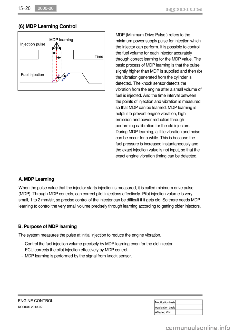
MDP (Minimum Drive Pulse ) refers to the
minimum power supply pulse for injection which
the injector can perform. It is possible to control
the fuel volume for each injector accurately
through correct learning for the MDP value. The
basic process of MDP learning is that the pulse
slightly higher than MDP is supplied and then (b)
the vibration generated from the cylinder is
detected. The knock sensor detects the
vibration from the engine after a small volume of
fuel is injected. And the time interval between
the points of injection and vibration is measured
so that MDP can be learned. MDP learning is
helpful to prevent engine vibration, high
emission and power reduction through
performing calibration for the old injectors.
During MDP learning, a little vibration and noise
can be occur for a while. This is because the
fuel pressure is increased instantaneously and
the exact injection value is not input, so that the
exact engine vibration timing can be detected.
(6) MDP Learning Control
A. MDP Learning
When the pulse value that the injector starts injection is measured, it is called minimum drive pulse
(MDP). Through MDP controls, can correct pilot injections effectively. Pilot injection volume is very
small, 1 to 2 mm/str, so precise control of the injector can be difficult if it gets old. So there needs MDP
learning to control the very small volume precisely through learning according to getting older injectors.
Control the fuel injection volume precisely by MDP learning even for the old injector.
ECU corrects the pilot injection effectively by MDP control.
MDP learning is performed by the signal from knock sensor. -
-
- The system measures the pulse at initial injection to reduce the engine vibration.
B. Purpose of MDP learning
Page 381 of 796

01-6
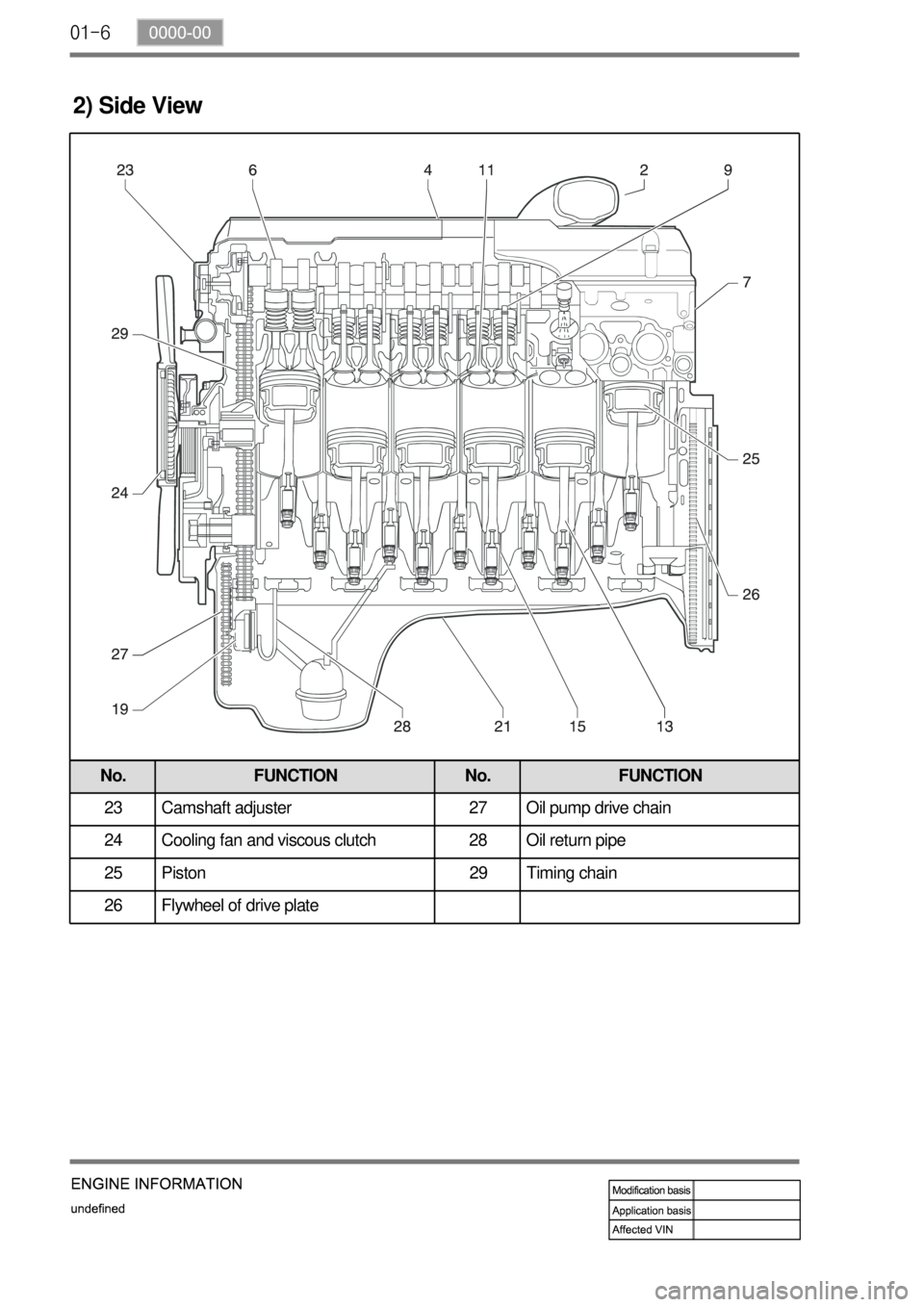
2) Side View
No. FUNCTION No. FUNCTION
23 Camshaft adjuster 27 Oil pump drive chain
24 Cooling fan and viscous clutch 28 Oil return pipe
25 Piston 29 Timing chain
26 Flywheel of drive plate
Page 394 of 796

06-4
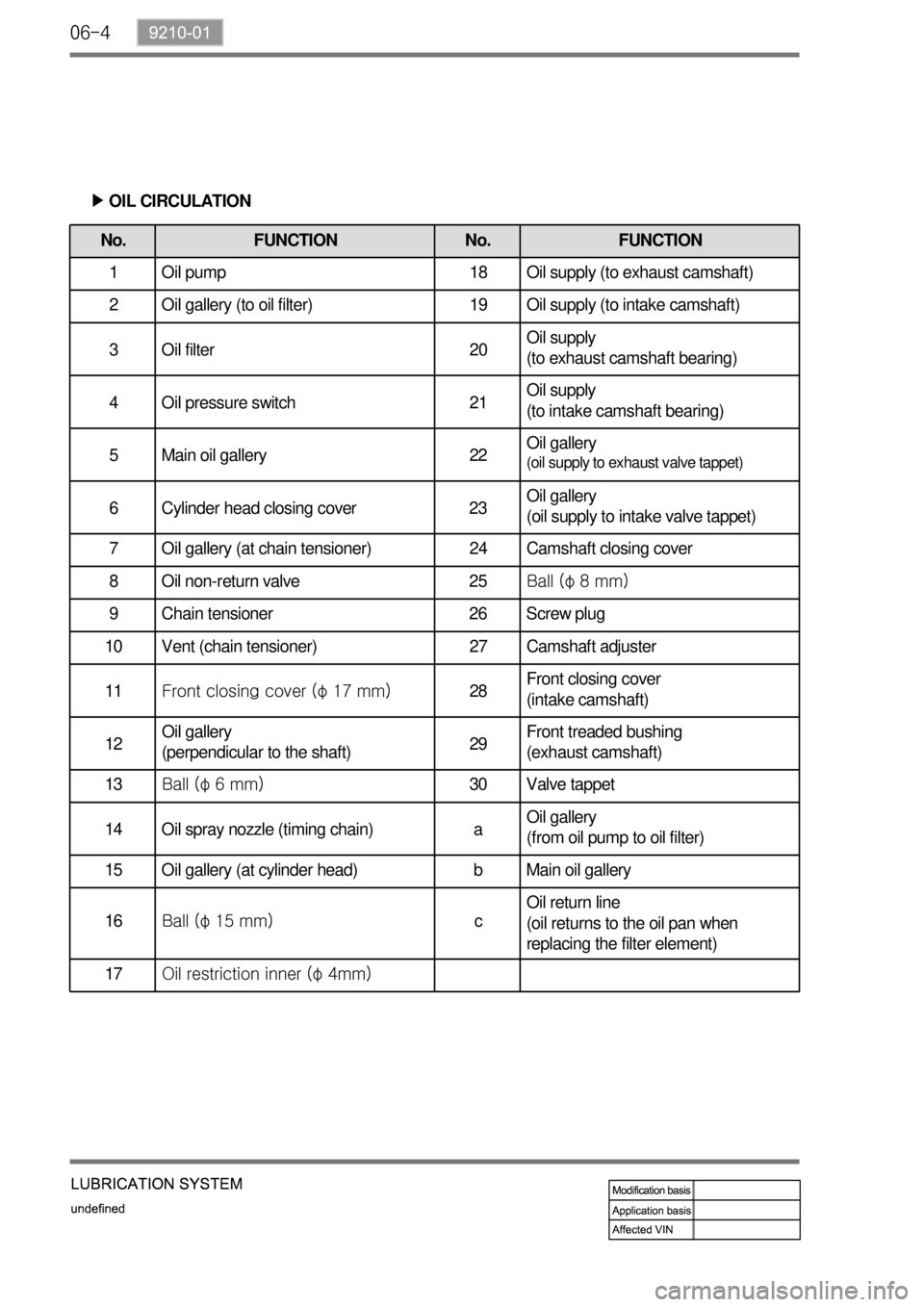
No. FUNCTION No. FUNCTION
1 Oil pump 18 Oil supply (to exhaust camshaft)
2 Oil gallery (to oil filter) 19 Oil supply (to intake camshaft)
3 Oil filter 20Oil supply
(to exhaust camshaft bearing)
4 Oil pressure switch 21Oil supply
(to intake camshaft bearing)
5 Main oil gallery 22Oil gallery
(oil supply to exhaust valve tappet)
6 Cylinder head closing cover 23Oil gallery
(oil supply to intake valve tappet)
7 Oil gallery (at chain tensioner) 24 Camshaft closing cover
8 Oil non-return valve 25Ball (φ 8 mm)
9 Chain tensioner 26 Screw plug
10 Vent (chain tensioner) 27 Camshaft adjuster
11Front closing cover (φ 17 mm)28Front closing cover
(intake camshaft)
12Oil gallery
(perpendicular to the shaft)29Front treaded bushing
(exhaust camshaft)
13Ball (φ 6 mm)30 Valve tappe
t
14 Oil spray nozzle (timing chain) aOil gallery
(from oil pump to oil filter)
15 Oil gallery (at cylinder head) b Main oil gallery
16Ball (φ 15 mm)cOil return line
(oil returns to the oil pan when
replacing the filter element)
17Oil restriction inner (φ 4mm)
OIL CIRCULATION ▶
Page 398 of 796

07-6
1. GENERAL DESCRIPTION
The cooling system maintains the engine temperature at an efficient level during all engine operating
conditions. When the engine is cold, the cooling system cools the engine slowly or not at all. This slo
w
cooling of the engine allows the engine to warm up quickly. The cooling system includes a radiator and
recovery subsystem, cooling fans, a thermostat and housing, a water pump, and a water pump drive
belt. The timing belt drives the water pump. All components must function properly for the cooling
system to operation. The water pump draws the coolant from the radiator.
The coolant then circulates through water jackets in the engine block, the intake manifold, and the
cylinder head. When the coolant reaches the operating temperature of the thermostat, the thermostat
opens. The coolant then goes back to the radiator where it cools. This system directs some coolant
through the hoses to the heat core. This provides for heating and defrosting. The coolant reservoir is
connected to the radiator to recover the coolant displaced by expansion from the high temperatures.
The coolant reservoir maintains the correct coolant level. The cooling system for this vehicle has no
radiator cap or filler neck. The coolant is added to the cooling system through the coolant reservoir.
Page 404 of 796

08-6
3. IGNITION SYSTEM OPERATION
This ignition system does not use a conventional distributor and coil. It uses a crankshaft position
sensor input to the Engine Control Module (ECM).
The ECM then determines Electronic Spark Timing (EST) and triggers the electronic ignition system
ignition coil.
This type of distributor less ignition system uses a "waste spark" method of spark distribution. Each
cylinder is paired with the cylinder that is opposite it (2.3L DOHC: 2 - 3 or 1 - 4, 3.2L DOHC: 1 - 6 or 2 -
5 or 3 - 4).
The spark occurs simultaneously in the cylinder coming up on the compression stroke and in the
cylinder coming up on the exhaust stroke.
The cylinder on the exhaust stroke requires very little of the available energy to fire the spark plug.
The remaining energy is available to the spark plug in the cylinder on the compression stroke. These
systems use the EST signal from the ECM to control the EST.
The ECM uses the following information: Engine load (mass air flow sensor, manifold air pressure
sensor).
Engine coolant temperature.
Intake air temperature.
Crankshaft position.
Engine speed (rpm).
1) Electronic Ignition System Ignition Coil
The Electronic Ignition (EI) system ignition coil is located on the cylinder head cover.
The double ended coils receive the signal for the ECM which controls the spark advance. Each
EI system ignition coil provides the high voltage to two spark plugs simultaneously;
3.2L DOHC
T1/1: cylinder 2 and 5
T1/2: cylinder 3 and 4
T1/3: cylinder 1 and 6
The EI system ignition coil is not serviceable and must be replaced as an assembly.
Page 669 of 796

09-234891-01
(2) Hydraulic Circuit of HBA
The above figure shows one front and one rear wheel and the same hydraulic circuit forms as in the
ESP operation. When HECU recognizes that it is an emergency and it is required for hard braking,
depending on the pressure value of the brake pressure sensor and pressure changes caused by the
pressure sensor timing, it operates the pump immediately to apply the brake pressure at the wheels.
Then, the pressure in the pump increases until just before the corresponding wheel gets locked. The
motor still keeps rotating and the outlet valve and the separation valve will stay closed. When the wheel
starts to lock, the HBA function cancels and switches to ABS operation.