alternator SSANGYONG TURISMO 2013 Service Manual
[x] Cancel search | Manufacturer: SSANGYONG, Model Year: 2013, Model line: TURISMO, Model: SSANGYONG TURISMO 2013Pages: 796, PDF Size: 78.99 MB
Page 148 of 796
01-4
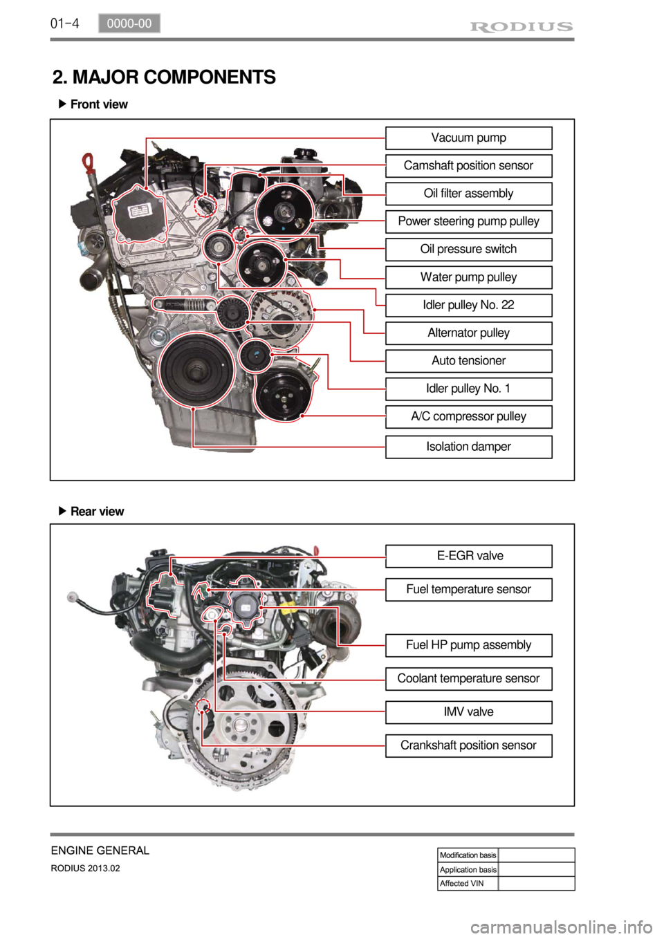
2. MAJOR COMPONENTS
Front view ▶
Vacuum pump
Camshaft position sensor
Oil filter assembly
Power steering pump pulley
Oil pressure switch
Water pump pulley
Idler pulley No. 22
Alternator pulley
Auto tensioner
Idler pulley No. 1
A/C compressor pulley
Rear view ▶
E-EGR valve
Fuel temperature sensor
Fuel HP pump assembly
Coolant temperature sensor
Crankshaft position sensorIMV valve
Isolation damper
Page 157 of 796
01-130000-00
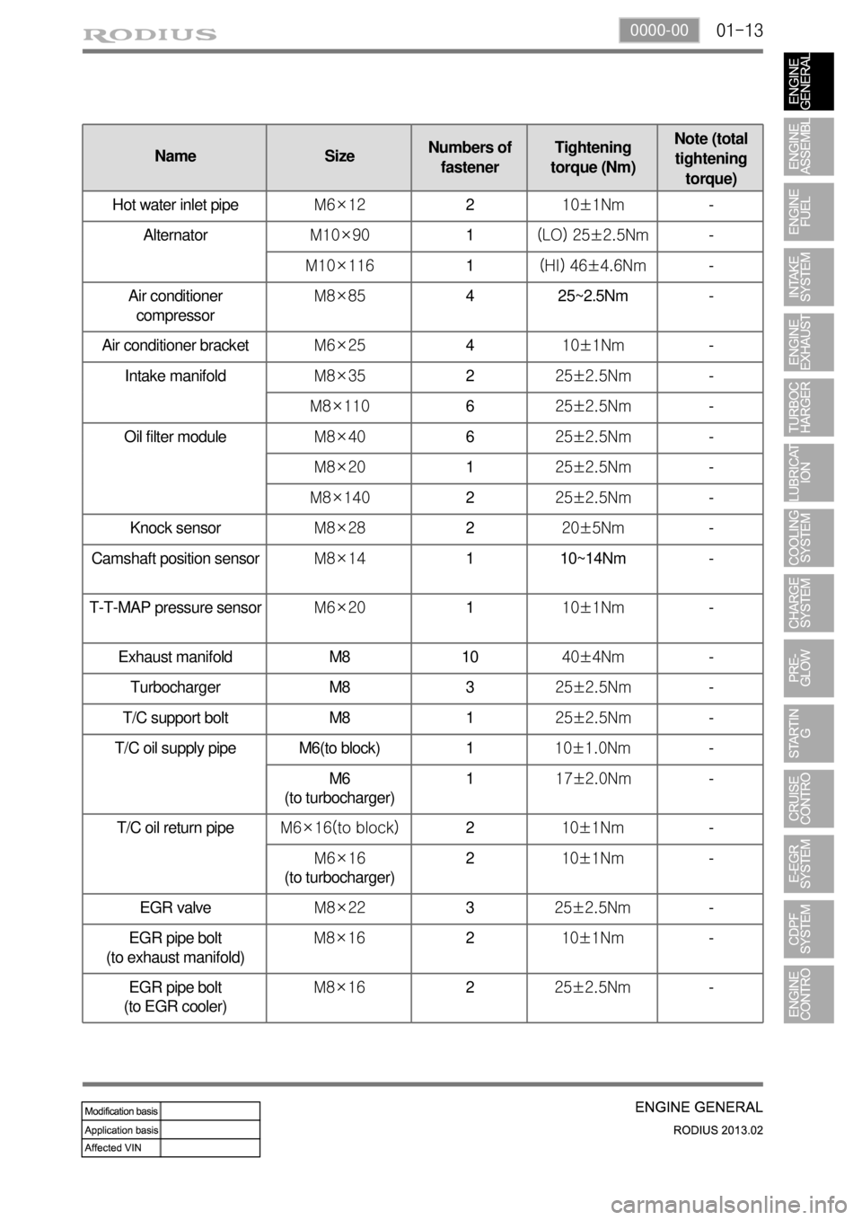
T/C oil supply pipe M6(to block) 1 10±1.0Nm -
M6
(to turbocharger)1 17±2.0Nm-
T/C oil return pipeM6×16(to block)2 10±1Nm -
M6×16
(to turbocharger)210±1Nm -
EGR valveM8×223 25±2.5Nm -
EGR pipe bolt
(to exhaust manifold)M8×16 2 10±1Nm -
EGR pipe bolt
(to EGR cooler)M8×16 2 25±2.5Nm -
Name SizeNumbers of
fastenerTightening
torque (Nm)Note (total
tightening
torque)
Hot water inlet pipeM6×12210±1Nm-
AlternatorM10×901(LO) 25±2.5Nm -
M10×1161(HI) 46±4.6Nm -
Air conditioner
compressorM8×854 25~2.5Nm -
Air conditioner bracketM6×25410±1Nm-
Intake manifoldM8×35225±2.5Nm-
M8×110625±2.5Nm-
Oil filter moduleM8×40625±2.5Nm-
M8×20125±2.5Nm-
M8×140225±2.5Nm-
Knock sensorM8×28220±5Nm-
Camshaft position sensorM8×141 10~14Nm -
T-T-MAP pressure sensorM6×20110±1Nm-
Exhaust manifold M8 1040±4Nm-
Turbocharger M8 325±2.5Nm-
T/C support bolt M8 125±2.5Nm-
Page 165 of 796
02-6
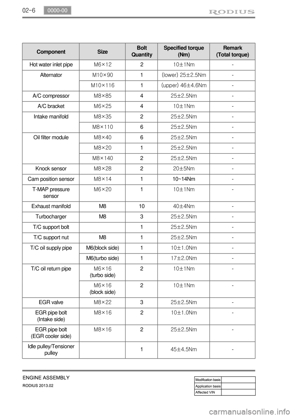
Component SizeBolt
QuantitySpecified torque
(Nm)Remark
(Total torque)
Hot water inlet pipeM6×12210±1Nm-
AlternatorM10×901(lower) 25±2.5Nm-
M10×1161(upper) 46±4.6Nm-
A/C compressorM8×85425±2.5Nm-
A/C bracketM6×25410±1Nm-
Intake manifoldM8×35225±2.5Nm-
M8×110625±2.5Nm-
Oil filter moduleM8×40625±2.5Nm-
M8×20125±2.5Nm-
M8×140225±2.5Nm-
Knock sensorM8×28220±5Nm-
Cam position sensorM8×141 10~14Nm -
T-MAP pressure
sensorM6×20110±1Nm-
Exhaust manifold M8 1040±4Nm-
Turbocharger M8 325±2.5Nm-
T/C support bolt 125±2.5Nm-
T/C support nut M8 125±2.5Nm-
T/C oil supply pipe M6(block side) 110±1.0Nm-
M6(turbo side) 117±2.0Nm-
T/C oil return pipeM6×16
(turbo side)210±1Nm-
M6×16
(block side)210±1Nm-
EGR valveM8×22325±2.5Nm-
EGR pipe bolt
(Intake side)M8×16210±1.0Nm-
EGR pipe bolt
(EGR cooler side)M8×16225±2.5Nm-
Idle pulley/Tensioner
pulley145±4.5Nm -
Page 173 of 796

02-14
D20DTR Engine
1. BELT LAYOUT
It is single drive type and uses FEAD (Front End Accessories Drive) design to make a compact layout.
Components ▶
HPS
(Hydraulic Power Steering)
1 Crankshaft pulley (DDU)
2 Auto tensioner
3 Tensioner pulley
4 Vacuum pump
5 A/C compressor pulley
6 Alternator pulley
7 Water pump pulley
8 Idle pulley #1
9 Idle pulley #2
10 Power steering pump pulley
Page 279 of 796
09-31451-01
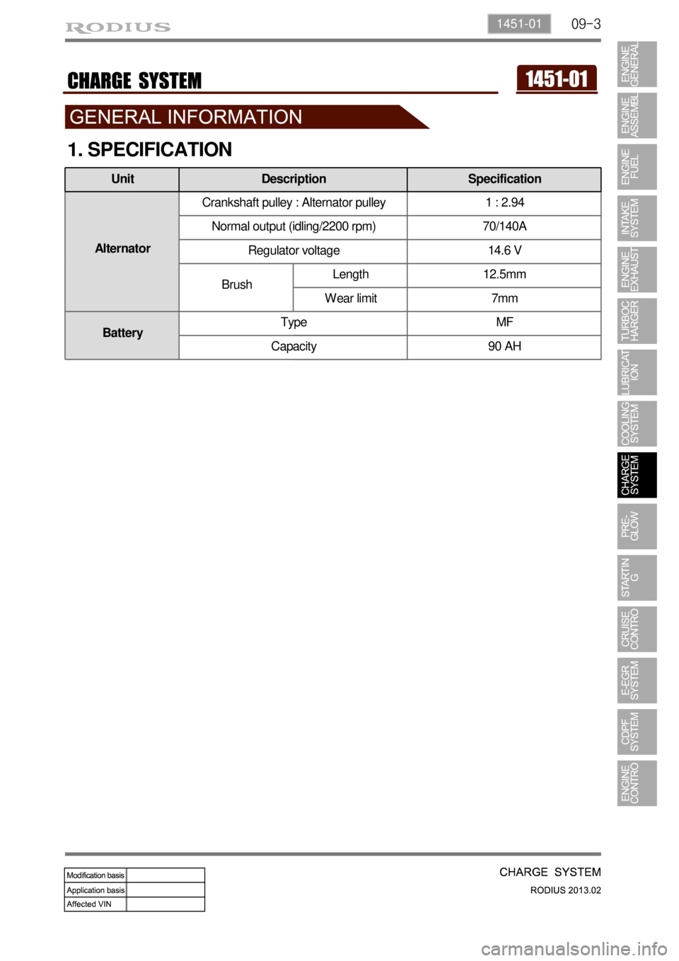
1. SPECIFICATION
AlternatorCrankshaft pulley : Alternator pulley 1 : 2.94
Normal output (idling/2200 rpm) 70/140A
Regulator voltage 14.6 V
BrushLength 12.5mm
Wear limit 7mm
BatteryType MF
Capacity 90 AH
Unit Description Specification
Page 280 of 796

09-4
2. INSPECTION
1) Alternator Output Test
Item How to check DTC set value / Action
Output
current
B terminal
current
Rotor
coil
resistance
D terminal
voltage
Disconnect the cable connected to the B
terminal on the alternator. Connect one
end of the ammeter to the B terminal and
the other end to the cable connected to
the B terminal.
Measure the maximum output value.
(Maintain the engine speed between
2,500 and 3,000 rpm.)
(Turn the headlamp and all the electrical
switches on.) 1.
2.Pass: If the measured current is 45
A or higher.
Fail: If the measured current is less
than 45 A.
Check the current of the B
terminal. -
-
-
Move the gear selector lever to the neutral
position.
Maintain the engine speed at 2,500 rpm
with the vehicle unloaded.
(Turn all the electrical switches off.) 1.
2.Open circuit: If the measured
current is 5 A or higher. -
Disconnect the negative cable from the
battery.
Remove the B terminal and turn off the
ignition switch.
Measure the resistance between the L and
F terminals with an ohmmeter. 1.
2.
3.Pass: If the measured resistance is
between 3 and 6 Ω.
Faulty rotor coil or slip ring: If the
measured resistance is less than 3
Ω or greater than 6 Ω. -
-
Connect the B terminal wiring.
Measure the voltage with the engine
running. 1.
2.Specification: 12.5 V to 14.5 V
Faulty IC regulator or field coil: If
the measured voltage is 14.5 V or
higher. -
-
Disconnect the negative battery cable.
Connect the negative cable again after connecting the ammeter. -
-
Page 281 of 796
09-51451-01
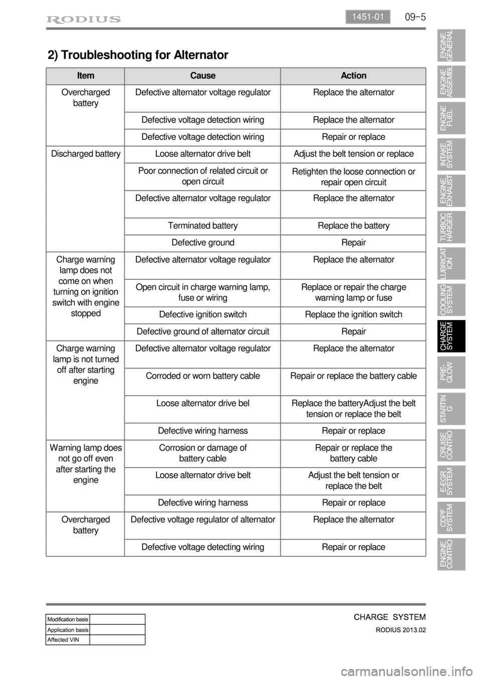
2) Troubleshooting for Alternator
Item Cause Action
Overcharged
batteryDefective alternator voltage regulator Replace the alternator
Defective voltage detection wiring Replace the alternator
Defective voltage detection wiring Repair or replace
Discharged battery Loose alternator drive belt Adjust the belt tension or replace
Poor connection of related circuit or
open circuitRetighten the loose connection or
repair open circuit
Defective alternator voltage regulator Replace the alternator
Terminated battery Replace the battery
Defective ground Repair
Charge warning
lamp does not
come on when
turning on ignition
switch with engine
stoppedDefective alternator voltage regulator Replace the alternator
Open circuit in charge warning lamp,
fuse or wiringReplace or repair the charge
warning lamp or fuse
Defective ignition switch Replace the ignition switch
Defective ground of alternator circuit Repair
Charge warning
lamp is not turned
off after starting
engineDefective alternator voltage regulator Replace the alternator
Corroded or worn battery cable Repair or replace the battery cable
Loose alternator drive bel Replace the batteryAdjust the belt
tension or replace the belt
Defective wiring harness Repair or replace
Warning lamp does
not go off even
after starting the
engineCorrosion or damage of
battery cableRepair or replace the
battery cable
Loose alternator drive belt Adjust the belt tension or
replace the belt
Defective wiring harness Repair or replace
Overcharged
batteryDefective voltage regulator of alternator Replace the alternator
Defective voltage detecting wiring Repair or replace
Page 283 of 796
09-71451-01
(1) Checking
Using battery tester ▶
PASS (11.0 V or more): Explain to the customer that the battery is reusable.
Need to be charged (9.0 to 11.0 V): Charge the battery with a charger and reinstall it. Explain it
to the customer.
Need to be replaced (9.0 V or more): The battery should be replaced due to overdischarging. -
-
-
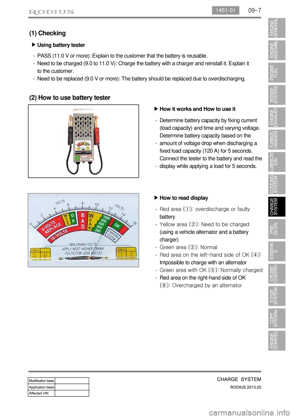
(2) How to use battery tester
How it works and How to use it ▶
Determine battery capacity by fixing current
(load capacity) and time and varying voltage.
Determine battery capacity based on the
amount of voltage drop when discharging a
fixed load capacity (120 A) for 5 seconds.
Connect the tester to the battery and read the
display while applying a load for 5 seconds. -
-
-
How to read display ▶
Red area (①): overdischarge or faulty
battery
Yellow area (②): Need to be charged
(using a vehicle alternator and a battery
charger)
Green area (③): Normal
Red area on the left-hand side of OK (④):
Impossible to charge with an alternator
Green area with OK (⑤): Normally charged
Red area on the right-hand side of OK
(⑥): Overcharged by an alternator -
-
-
-
-
-
Page 286 of 796

09-10
Alternator
The alternator charges the battery and
supplies power to each electric unit by
converting the mechanical energy to the
electrical energy.
1. SYSTEM DESCRIPTION
1) Overview
The charge system is designed to supply electrical energy to the vehicle while driving, and supplies a
constant direct current voltage by converting mechanical rotational movement to electrical energy.
The voltage regulator on the back of the alternator controls the generated voltage in all rotating ranges and
adjusts the system voltage according to the electric load and ambient temperature change.
2) System Layout (Locations)
Battery
It converts the chemical energy to the
electrical energy and supplies power to the
corresponding electric units when starting
the engine.
Page 288 of 796
09-12
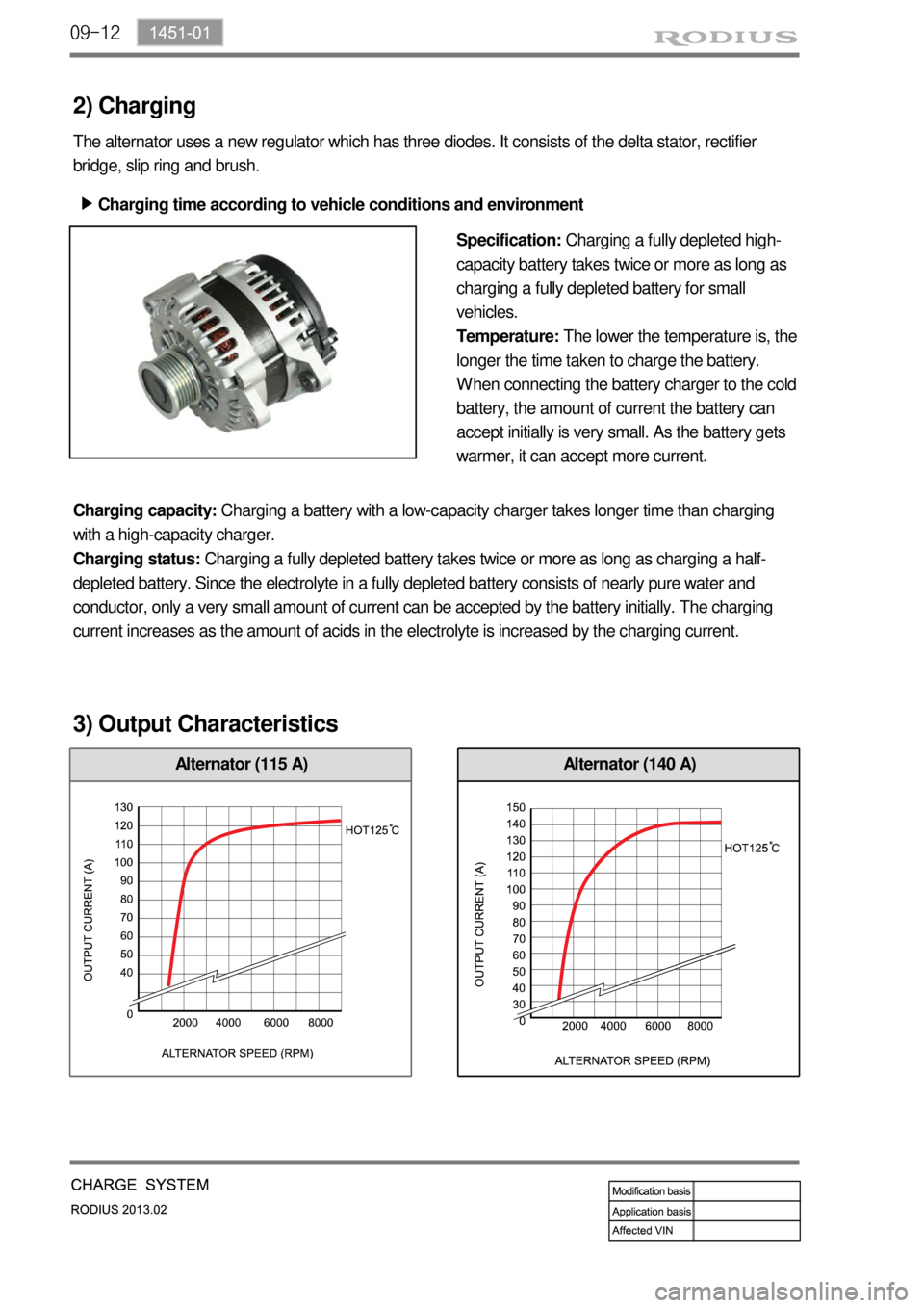
Alternator (115 A)
2) Charging
The alternator uses a new regulator which has three diodes. It consists of the delta stator, rectifier
bridge, slip ring and brush.
Charging time according to vehicle conditions and environment ▶
Specification: Charging a fully depleted high-
capacity battery takes twice or more as long as
charging a fully depleted battery for small
vehicles.
Temperature:The lower the temperature is, the
longer the time taken to charge the battery.
When connecting the battery charger to the cold
battery, the amount of current the battery can
accept initially is very small. As the battery gets
warmer, it can accept more current.
Charging capacity: Charging a battery with a low-capacity charger takes longer time than charging
with a high-capacity charger.
Charging status: Charging a fully depleted battery takes twice or more as long as charging a half-
depleted battery. Since the electrolyte in a fully depleted battery consists of nearly pure water and
conductor, only a very small amount of current can be accepted by the battery initially. The charging
current increases as the amount of acids in the electrolyte is increased by the charging current.
3) Output Characteristics
Alternator (140 A)