brake SUBARU BRZ 2015 1.G Workshop Manual
[x] Cancel search | Manufacturer: SUBARU, Model Year: 2015, Model line: BRZ, Model: SUBARU BRZ 2015 1.GPages: 492, PDF Size: 6.53 MB
Page 396 of 492
396
5-2. Steps to take in an emergency
Emergency start function (vehicles with a keyless access with
push button start system)When the engine does not start, the following steps can be used as
an interim measure to start the engine if the push-button ignition
switch is functioning normally:
Vehicles with an automatic transmission Set the parking brake.
Put the select lever in P.
Set the push-button ignition switch to “ACC” mode.
Press and hold the push-button ignition switch about 15 sec-
onds while depressing the brake pedal firmly.
Even if the engine can be started using the above steps, the system
may be malfunctioning. Have the vehicle checked by your SUBARU
dealer.
■The starter motor does not turn over, the interior lights and
headlights do not turn on, or the horn does not sound.
One of the following may be the cause of the problem. ● One or both of the battery terminals may be disconnected.
● The battery may be discharged. ( →P. 404)
● There may be a malfunction in the steering lock system. (vehi-
cles with a keyless access with push button start system)
Contact your SUBARU dealer if the problem cannot be repaired, or if
repair procedures are unknown.
STEP 1
STEP 2
STEP 3
STEP 4
Page 397 of 492
5
When trouble arises
397
5-2. Steps to take in an emergency
Vehicles with a manual transmissionSet the parking brake.
Put the shift lever in neutral.
Turn the push-button ignition switch to “ACC” mode.
Push and hold the push-button ignition switch for about 15
seconds while depressing the brake pedal and clutch pedal
firmly.
Even if the engine can be started using the above steps, the system
may be malfunctioning. Have the vehicle checked by your SUBARU
dealer.
STEP 1
STEP2
STEP 3
STEP 4
Page 398 of 492
398
5-2. Steps to take in an emergency
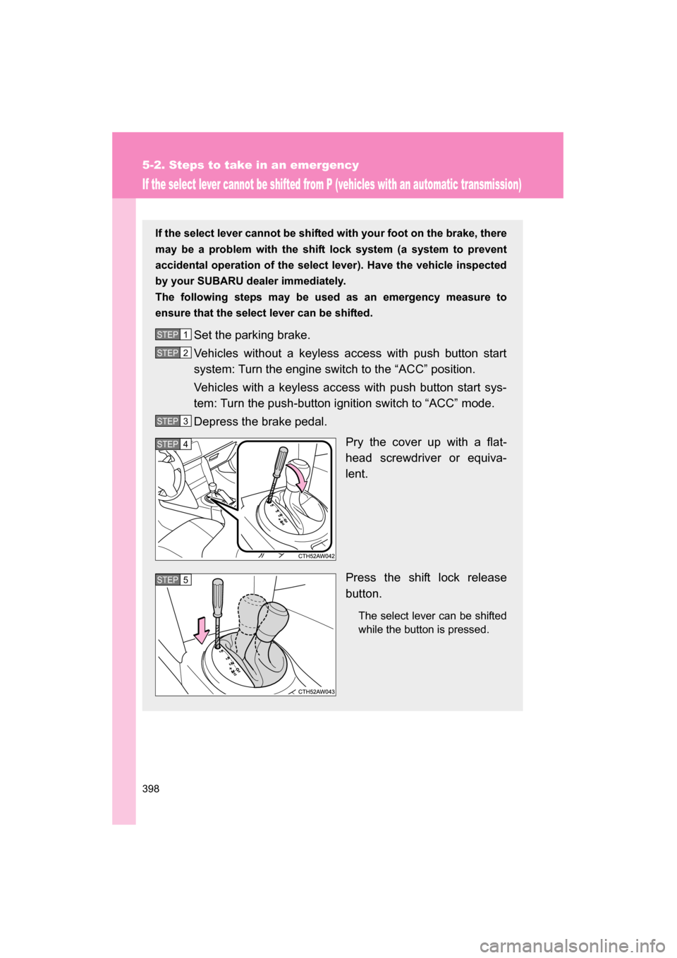
If the select lever cannot be shifted from P (vehicles with an automatic transmission)
If the select lever cannot be shifted with your foot on the brake, there
may be a problem with the shift lock system (a system to prevent
accidental operation of the select lever). Have the vehicle inspected
by your SUBARU dealer immediately.
The following steps may be used as an emergency measure to
ensure that the select lever can be shifted.Set the parking brake.
Vehicles without a keyless access with push button start
system: Turn the engine switch to the “ACC” position.
Vehicles with a keyless access with push button start sys-
tem: Turn the push-button ignition switch to “ACC” mode.
Depress the brake pedal. Pry the cover up with a flat-
head screwdriver or equiva-
lent.
Press the shift lock release
button.
The select lever can be shifted
while the button is pressed.
STEP 1
STEP 2
STEP 3
STEP 4
STEP 5
Page 401 of 492
5
When trouble arises
401
5-2. Steps to take in an emergency
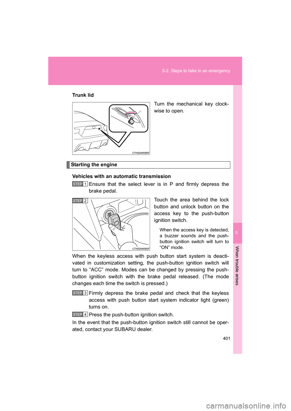
Trun k li dTurn the mechanical key clock-
wise to open.
Starting the engine
Vehicles with an automatic transmission Ensure that the select lever is in P and firmly depress the
brake pedal.
Touch the area behind the lock
button and unlock button on the
access key to the push-button
ignition switch.
When the access key is detected,
a buzzer sounds and the push-
button ignition switch will turn to
“ON” mode.
When the keyless access with push button start system is deacti-
vated in customization setting, the push-button ignition switch will
turn to “ACC” mode. Modes can be changed by pressing the push-
button ignition switch with the brake pedal released. (The mode
changes each time the switch is pressed.)
Firmly depress the brake pedal and check that the keyless
access with push button start system indicator light (green)
turns on.
Press the push-button ignition switch.
In the event that the push-button ignition switch still cannot be oper-
ated, contact your SUBARU dealer.
STEP 1
STEP 2
STEP 3
STEP 4
Page 412 of 492
412
5-2. Steps to take in an emergency
If the vehicle becomes stuck
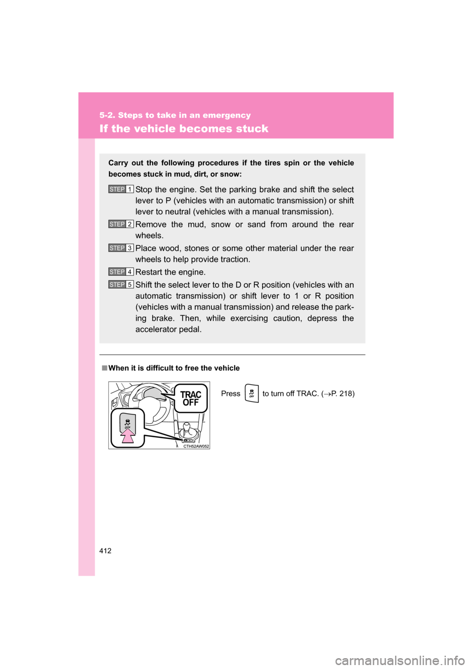
■When it is difficult to free the vehicle
Carry out the following procedures
if the tires spin or the vehicle
becomes stuck in mud, dirt, or snow:
Stop the engine. Set the parking brake and shift the select
lever to P (vehicles with an automatic transmission) or shift
lever to neutral (vehicles with a manual transmission).
Remove the mud, snow or sand from around the rear
wheels.
Place wood, stones or some other material under the rear
wheels to help provide traction.
Restart the engine.
Shift the select lever to the D or R position (vehicles with an
automatic transmission) or shift lever to 1 or R position
(vehicles with a manual transmission) and release the park-
ing brake. Then, while exercising caution, depress the
accelerator pedal.
STEP 1
STEP 2
STEP 3
STEP 4
STEP 5
Press to turn off TRAC. ( →P. 218)
Page 425 of 492
425
6-1. Specifications
6
Vehicle specifications
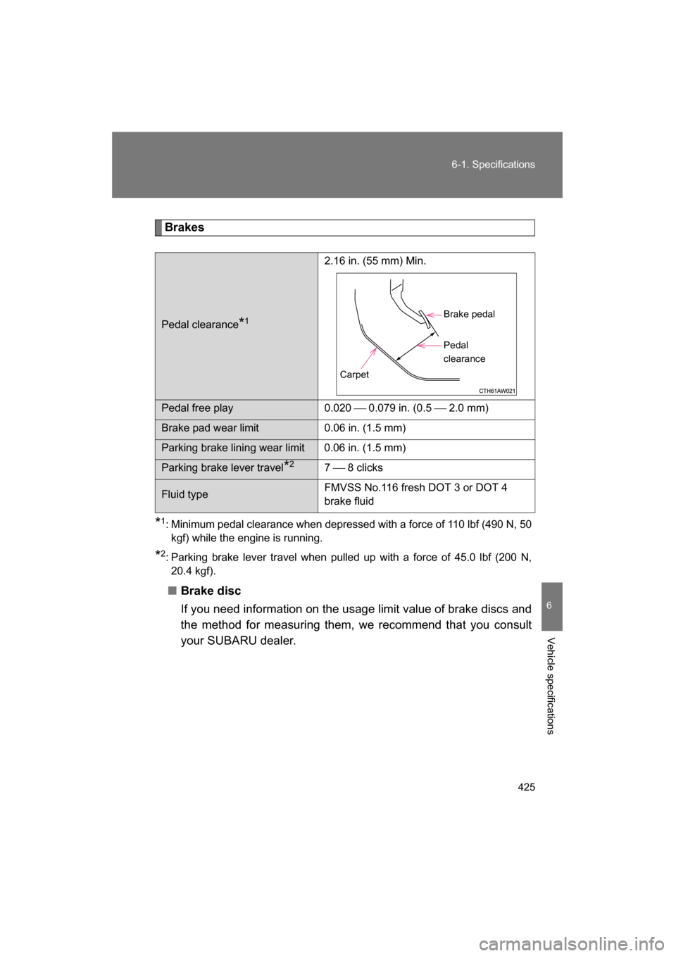
Brakes
* 1
: Minimum pedal clearance when depressed with a force of 110 lbf (490 N, 50
kgf) while the engine is running.
* 2
: Parking brake lever travel when pulled up with a force of 45.0 lbf (200 N,
20.4 kgf).
■Brake disc
If you need information on the usage limit value of brake discs and
the method for measuring them, we recommend that you consult
your SUBARU dealer.
Pedal clearance *1 2.16 in. (55 mm) Min.
Pedal free play 0.020
0.079 in. (0.5 2.0 mm)
Brake pad wear limit 0.06 in. (1.5 mm)
Parking brake lining wear limit 0.06 in. (1.5 mm)
Parking brake lever travel *2
7 8 clicks
Fluid type FMVSS No.116 fresh DOT 3 or DOT 4
brake fluid
Brake pedal
Pedal
clearance
Carpet
Page 438 of 492
438
6-1. Specifications
Warning: The temperature grades of a tire assume that it is properly
inflated and not overloaded.
Excessive speed, underinflation, or excessive loading, either sepa-
rately or in combination, can cause heat buildup and possible tire fail-
ure.
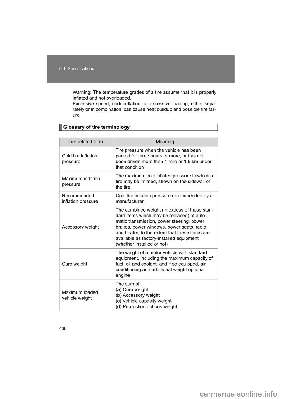
Glossary of tire terminology
Tire related termMeaning
Cold tire inflation
pressure Tire pressure when the vehicle has been
parked for three hours or more, or has not
been driven more than 1 mile or 1.5 km under
that condition
Maximum inflation
pressure The maximum cold inflated pressure to which a
tire may be inflated, shown on the sidewall of
the tire
Recommended
inflation pressure Cold tire inflation pressure recommended by a
manufacturer.
Accessory weight The combined weight (in excess of those stan-
dard items which may be replaced) of auto-
matic transmission, power steering, power
brakes, power windows, power seats, radio
and heater, to the extent that these items are
available as factory-installed equipment
(whether installed or not)
Curb weight The weight of a motor vehicle with standard
equipment, including the maximum capacity of
fuel, oil and coolant, and if so equipped, air
conditioning and additional weight optional
engine
Maximum loaded
vehicle weight The sum of:
(a) Curb weight
(b) Accessory weight
(c) Vehicle capacity weight
(d) Production options weight
Page 439 of 492
439
6-1. Specifications
6
Vehicle specifications
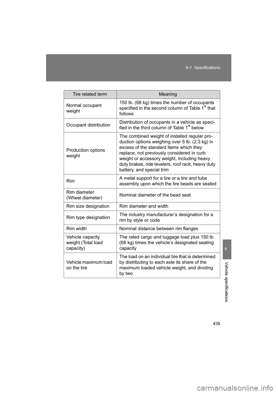
Tire related termMeaning
Normal occupant
weight 150 lb. (68 kg) times the number of occupants
specified in the second column of Table 1
* that
follows
Occupant distribution Distribution of occupants in a vehicle as speci-
fied in the third column of Table 1
* below
Production options
weight The combined weight of installed regular pro-
duction options weighing over 5 lb. (2.3 kg) in
excess of the standard items which they
replace, not previously considered in curb
weight or accessory weight, including heavy
duty brakes, ride levelers, roof rack, heavy duty
battery, and special trim
Rim A metal support for a tire or a tire and tube
assembly upon which the tire beads are seated
Rim diameter
(Wheel diameter) Nominal diameter of the bead seat
Rim size designation Rim diameter and width
Rim type designation The industry manufacturer’s designation for a
rim by style or code
Rim width Nominal distance between rim flanges
Vehicle capacity
weight (Total load
capacity) The rated cargo and luggage load plus 150 lb.
(68 kg) times the vehicle’s designated seating
capacity
Vehicle maximum load
on the tire The load on an individual tire that is determined
by distributing to each axle its share of the
maximum loaded vehicle weight, and dividing
by two
Page 476 of 492
476
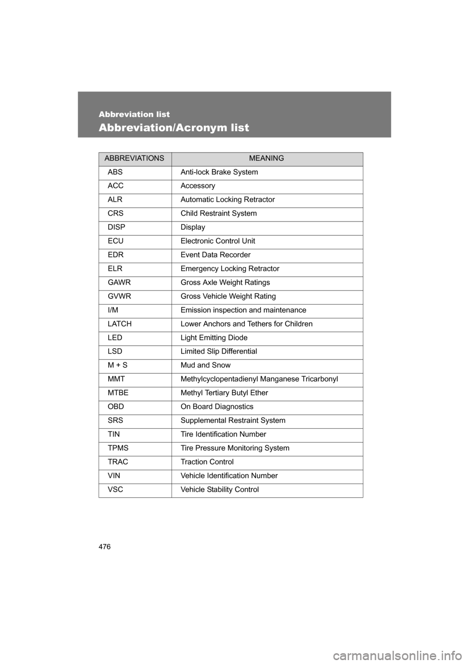
Abbreviation list
Abbreviation/Acronym list
ABBREVIATIONSMEANING
ABS Anti-lock Brake System
ACC Accessory
ALR Automatic Locking Retractor
CRS Child Restraint System
DISP Display
ECU Electronic Control Unit
EDR Event Data Recorder
ELR Emergency Locking Retractor
GAWR Gross Axle Weight Ratings
GVWR Gross Vehicle Weight Rating
I/M Emission inspection and maintenance
LATCH Lower Anchors and Tethers for Children
LED Light Emitting Diode
LSD Limited Slip Differential
M + S Mud and Snow
MMT Methylcyclopentadienyl Manganese Tricarbonyl
MTBE Methyl Tertiary Butyl Ether
OBD On Board Diagnostics
SRS Supplemental Restraint System
TIN Tire Identification Number
TPMS Tire Pressure Monitoring System
TRAC Traction Control
VIN Vehicle Identification Number
VSC Vehicle Stability Control
Page 477 of 492
477
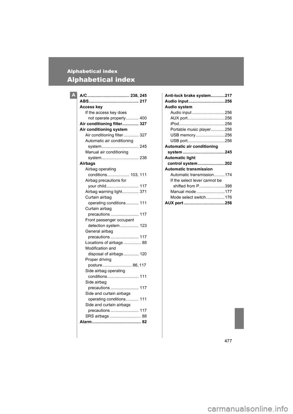
Alphabetical index
Alphabetical index
A/C .................................... 238, 245
ABS........................................... 217
Access keyIf the access key does not operate properly........... 400
Air conditioning filter.............. 327
Air conditioning system Air conditioning filter ............. 327
Automatic air conditioning
system................................ 245
Manual air conditioning system................................ 238
Airbags Airbag operating
conditions................... 103, 111
Airbag precautions for your child............................ 117
Airbag warning light .............. 371
Curtain airbag
operating conditions........... 111
Curtain airbag precautions ........................ 117
Front passenger occupant detection system ................ 123
General airbag precautions ........................ 117
Locations of airbags ............... 88
Modification and disposal of airbags ............. 120
Proper driving
posture ......................... 86, 117
Side airbag operating conditions........................... 111
Side airbag precautions ........................ 117
Side and curtain airbags
operating conditions........... 111
Side and curtain airbags precautions ........................ 117
SRS airbags ........................... 88
Alarm .......................................... 82 Anti-lock brake system............217
Audio input ...............................256
Audio system
Audio input ............................256
AUX port................................256
iPod .......................................256
Portable music player............256
USB memory .........................256
USB port................................256
Automatic air conditioning system ....................................245
Automatic light
control system .......................202
Automatic transmission
Automatic transmission .........174
If the select lever cannot be shifted from P......................398
Manual mode ........................177
Mode select switch ................176
AUX port ...................................256A