service SUBARU FORESTER 2004 Service Repair Manual
[x] Cancel search | Manufacturer: SUBARU, Model Year: 2004, Model line: FORESTER, Model: SUBARU FORESTER 2004Pages: 2870, PDF Size: 38.67 MB
Page 1544 of 2870
ME(H4DOTC)-84
MECHANICAL
Cylinder Block
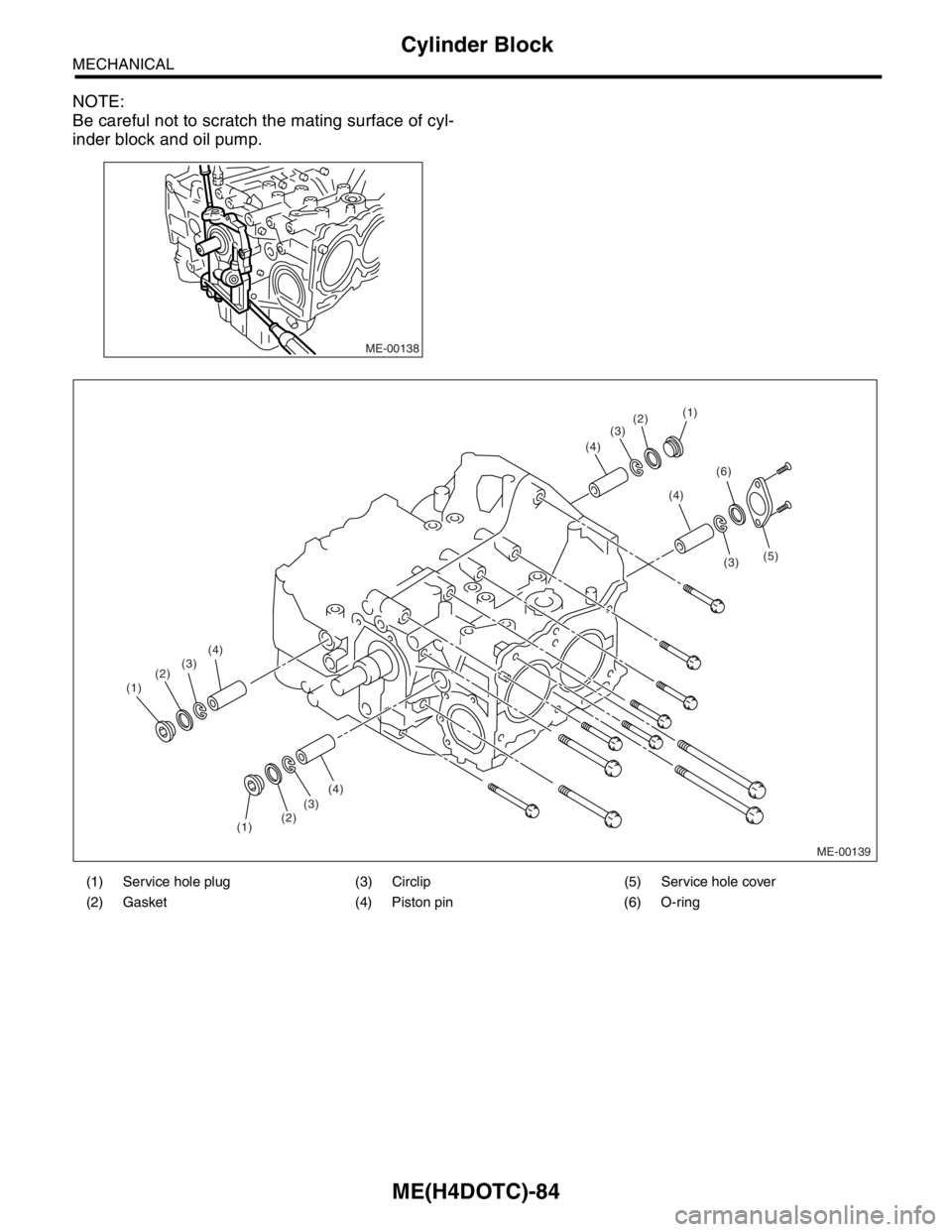
NOTE:
Be careful not to scratch the mating surface of cyl-
inder block and oil pump.
ME-00138
(1) Service hole plug (3) Circlip (5) Service hole cover
(2) Gasket (4) Piston pin (6) O-ring
ME-00139
(3)
(4) (2)(1)
(3)
(4)
(5)
(6)
(2)(3)
(2)
(1)(3)(4)
(4)
(1)
Page 1545 of 2870
![SUBARU FORESTER 2004 Service Repair Manual ME(H4DOTC)-85
MECHANICAL
Cylinder Block
24) Remove the service hole cover and service
hole plugs using hexagon wrench [14 mm (0.55
in)].
25) Rotate the crankshaft to bring #1 and #2 pis-
tons to botto SUBARU FORESTER 2004 Service Repair Manual ME(H4DOTC)-85
MECHANICAL
Cylinder Block
24) Remove the service hole cover and service
hole plugs using hexagon wrench [14 mm (0.55
in)].
25) Rotate the crankshaft to bring #1 and #2 pis-
tons to botto](/img/17/57426/w960_57426-1544.png)
ME(H4DOTC)-85
MECHANICAL
Cylinder Block
24) Remove the service hole cover and service
hole plugs using hexagon wrench [14 mm (0.55
in)].
25) Rotate the crankshaft to bring #1 and #2 pis-
tons to bottom dead center position, and then re-
move the piston circlip through service hole of #1
and #2 cylinders.
26) Draw out the piston pin from #1 and #2 pistons
using ST.
ST 499097600 PISTON PIN REMOVER (2.0
L model)
ST 499097700 PISTON PIN REMOVER (2.5
L model)
NOTE:
Be careful not to confuse the original combination
of piston, piston pin and cylinder.
27) Similarly remove the piston pins from #3 and #4
pistons.
28) Remove the bolts which connect the cylinder
block on the side of #2 and #4 cylinders.29) Back off the bolts which connect the cylinder
block on the side of #1 and #3 cylinders two or
three turns.
30) Set up the cylinder block so that #1 and #3 cyl-
inders are on the upper side, then remove the cyl-
inder block connecting bolts.
31) Separate the cylinder blocks (LH) and (RH).
ME-00140
ME-00141
ME-00142
ST
Page 1549 of 2870
ME(H4DOTC)-89
MECHANICAL
Cylinder Block
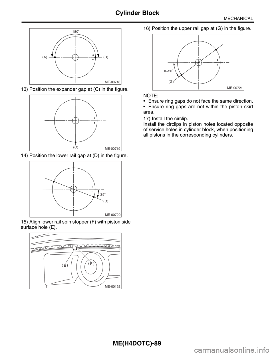
13) Position the expander gap at (C) in the figure.
14) Position the lower rail gap at (D) in the figure.
15) Align lower rail spin stopper (F) with piston side
surface hole (E).16) Position the upper rail gap at (G) in the figure.
NOTE:
Ensure ring gaps do not face the same direction.
Ensure ring gaps are not within the piston skirt
area.
17) Install the circlip.
Install the circlips in piston holes located opposite
of service holes in cylinder block, when positioning
all pistons in the corresponding cylinders.
ME-00718
(A)(B)
180
ME-00719
(C)
ME-00720
(D)
25
ME-00152
ME-00721
(G)
0 20
Page 1550 of 2870
ME(H4DOTC)-90
MECHANICAL
Cylinder Block
NOTE:
Use new circlips.
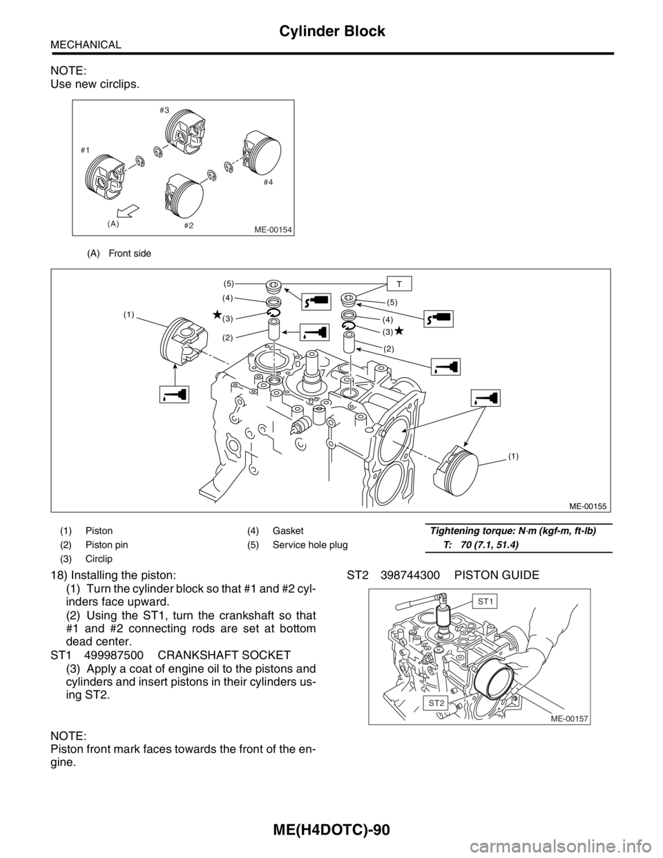
18) Installing the piston:
(1) Turn the cylinder block so that #1 and #2 cyl-
inders face upward.
(2) Using the ST1, turn the crankshaft so that
#1 and #2 connecting rods are set at bottom
dead center.
ST1 499987500 CRANKSHAFT SOCKET
(3) Apply a coat of engine oil to the pistons and
cylinders and insert pistons in their cylinders us-
ing ST2.ST2 398744300 PISTON GUIDE
NOTE:
Piston front mark faces towards the front of the en-
gine.
(A) Front side
ME-00154
#4 #3
#2 #1
(A)
(1) Piston (4) GasketTightening torque: N⋅m (kgf-m, ft-lb)
(2) Piston pin (5) Service hole plugT: 70 (7.1, 51.4)
(3) Circlip
ME-00155
(1) (1)
(2)
(2) (3)
(3) (4)
(4) (5)
(5)
T
ME-00157
ST2
ST1
Page 1551 of 2870
ME(H4DOTC)-91
MECHANICAL
Cylinder Block
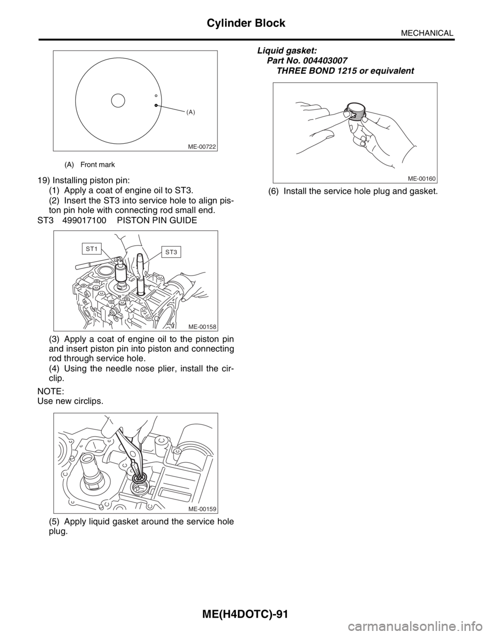
19) Installing piston pin:
(1) Apply a coat of engine oil to ST3.
(2) Insert the ST3 into service hole to align pis-
ton pin hole with connecting rod small end.
ST3 499017100 PISTON PIN GUIDE
(3) Apply a coat of engine oil to the piston pin
and insert piston pin into piston and connecting
rod through service hole.
(4) Using the needle nose plier, install the cir-
clip.
NOTE:
Use new circlips.
(5) Apply liquid gasket around the service hole
plug.Liquid gasket:
Part No. 004403007
THREE BOND 1215 or equivalent
(6) Install the service hole plug and gasket.
(A) Front mark
ME-00722
(A)
ME-00158
ST1ST3
ME-00159
ME-00160
Page 1552 of 2870
ME(H4DOTC)-92
MECHANICAL
Cylinder Block
NOTE:
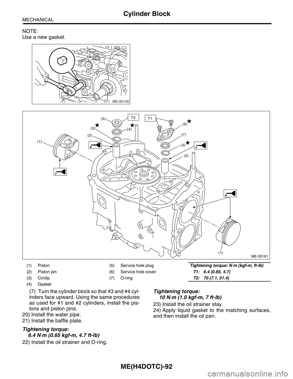
Use a new gasket.
(7) Turn the cylinder block so that #3 and #4 cyl-
inders face upward. Using the same procedures
as used for #1 and #2 cylinders, install the pis-
tons and piston pins.
20) Install the water pipe.
21) Install the baffle plate.
Tightening torque:
6.4 N
⋅m (0.65 kgf-m, 4.7 ft-lb)
22) Install the oil strainer and O-ring.Tightening torque:
10 N
⋅m (1.0 kgf-m, 7 ft-lb)
23) Install the oil strainer stay.
24) Apply liquid gasket to the matching surfaces,
and then install the oil pan.
ME-00140
(1) Piston (5) Service hole plugTightening torque: N⋅m (kgf-m, ft-lb)
(2) Piston pin (6) Service hole coverT1: 6.4 (0.65, 4.7)
(3) Circlip (7) O-ringT2: 70 (7.1, 51.4)
(4) Gasket
(1)(2)(3)
(1)
(2) (6)
(3)(7) (4) (5)
ME-00161
T2T1
Page 1559 of 2870
ME(H4DOTC)-99
MECHANICAL
Cylinder Block
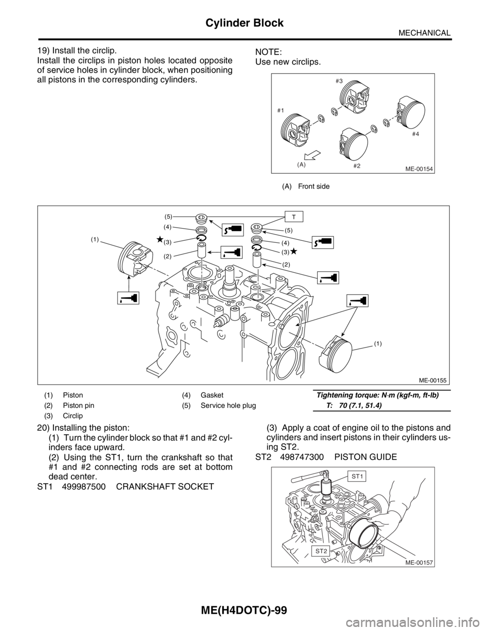
19) Install the circlip.
Install the circlips in piston holes located opposite
of service holes in cylinder block, when positioning
all pistons in the corresponding cylinders.NOTE:
Use new circlips.
20) Installing the piston:
(1) Turn the cylinder block so that #1 and #2 cyl-
inders face upward.
(2) Using the ST1, turn the crankshaft so that
#1 and #2 connecting rods are set at bottom
dead center.
ST1 499987500 CRANKSHAFT SOCKET(3) Apply a coat of engine oil to the pistons and
cylinders and insert pistons in their cylinders us-
ing ST2.
ST2 498747300 PISTON GUIDE
(A) Front side
ME-00154
#4 #3
#2 #1
(A)
(1) Piston (4) GasketTightening torque: N⋅m (kgf-m, ft-lb)
(2) Piston pin (5) Service hole plugT: 70 (7.1, 51.4)
(3) Circlip
ME-00155
(1) (1)
(2)
(2) (3)
(3) (4)
(4) (5)
(5)
T
ME-00157
ST2
ST1
Page 1560 of 2870
ME(H4DOTC)-100
MECHANICAL
Cylinder Block
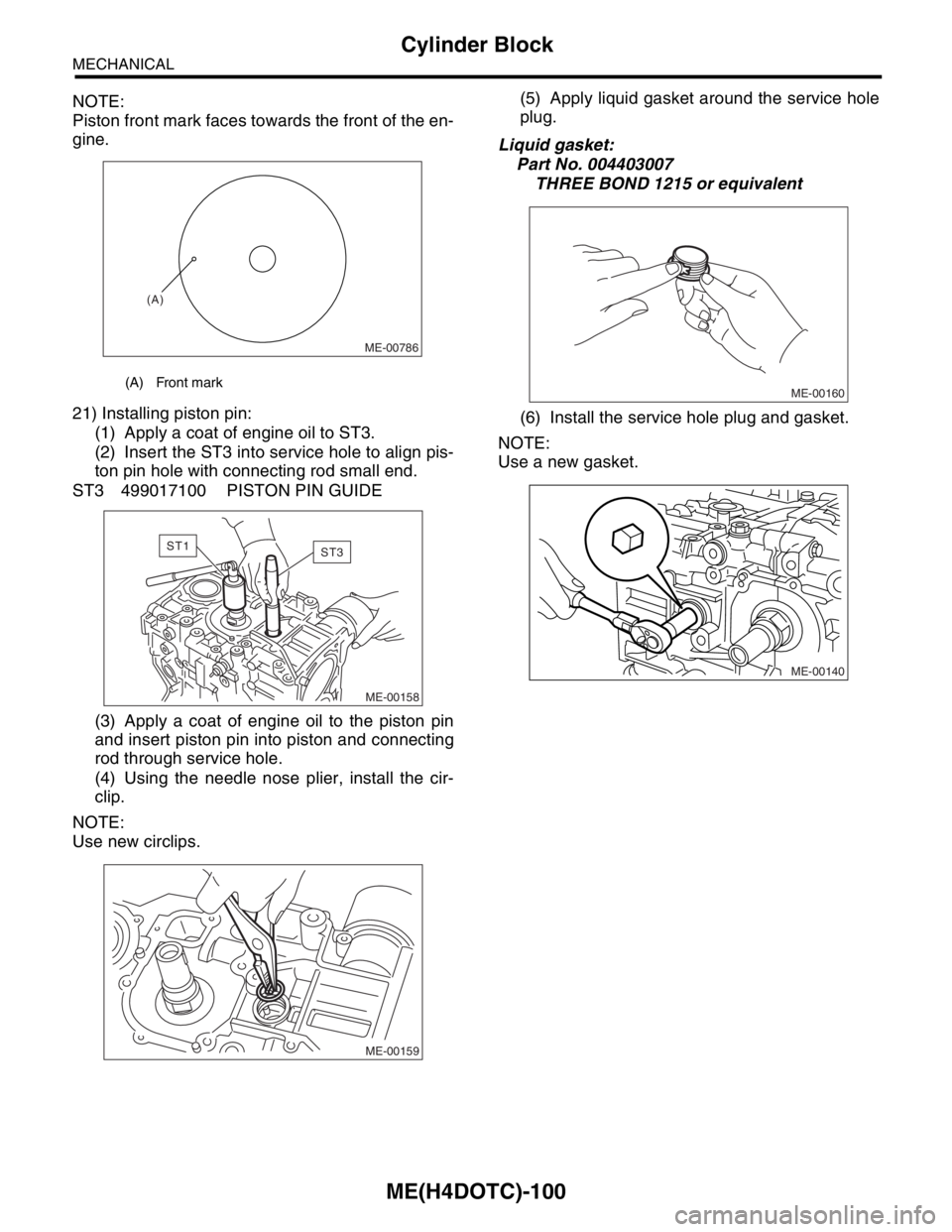
NOTE:
Piston front mark faces towards the front of the en-
gine.
21) Installing piston pin:
(1) Apply a coat of engine oil to ST3.
(2) Insert the ST3 into service hole to align pis-
ton pin hole with connecting rod small end.
ST3 499017100 PISTON PIN GUIDE
(3) Apply a coat of engine oil to the piston pin
and insert piston pin into piston and connecting
rod through service hole.
(4) Using the needle nose plier, install the cir-
clip.
NOTE:
Use new circlips.(5) Apply liquid gasket around the service hole
plug.
Liquid gasket:
Part No. 004403007
THREE BOND 1215 or equivalent
(6) Install the service hole plug and gasket.
NOTE:
Use a new gasket.
(A) Front mark
ME-00786
(A)
ME-00158
ST1ST3
ME-00159
ME-00160
ME-00140
Page 1561 of 2870
ME(H4DOTC)-101
MECHANICAL
Cylinder Block
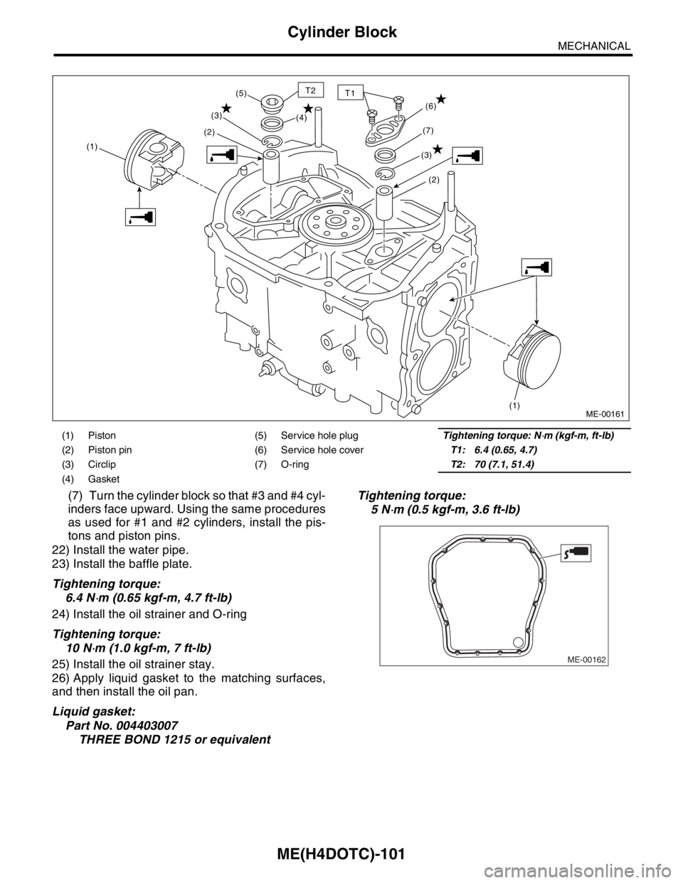
(7) Turn the cylinder block so that #3 and #4 cyl-
inders face upward. Using the same procedures
as used for #1 and #2 cylinders, install the pis-
tons and piston pins.
22) Install the water pipe.
23) Install the baffle plate.
Tightening torque:
6.4 N
⋅m (0.65 kgf-m, 4.7 ft-lb)
24) Install the oil strainer and O-ring
Tightening torque:
10 N
⋅m (1.0 kgf-m, 7 ft-lb)
25) Install the oil strainer stay.
26) Apply liquid gasket to the matching surfaces,
and then install the oil pan.
Liquid gasket:
Part No. 004403007
THREE BOND 1215 or equivalentTightening torque:
5 N
⋅m (0.5 kgf-m, 3.6 ft-lb)
(1) Piston (5) Service hole plugTightening torque: N⋅m (kgf-m, ft-lb)
(2) Piston pin (6) Service hole coverT1: 6.4 (0.65, 4.7)
(3) Circlip (7) O-ringT2: 70 (7.1, 51.4)
(4) Gasket
(1)(2)(3)
(1)
(2) (6)
(3)(7) (4) (5)
ME-00161
T2T1
ME-00162
Page 1585 of 2870
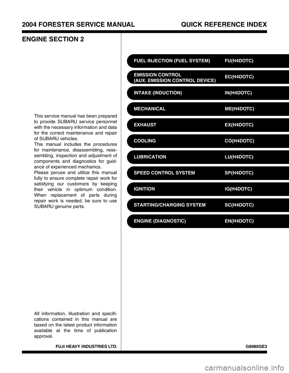
FUJI HEAVY INDUSTRIES LTD. G8080GE3
2004 FORESTER SERVICE MANUAL QUICK REFERENCE INDEX
ENGINE SECTION 2
This service manual has been prepared
to provide SUBARU service personnel
with the necessary information and data
for the correct maintenance and repair
of SUBARU vehicles.
This manual includes the procedures
for maintenance, disassembling, reas-
sembling, inspection and adjustment of
components and diagnostics for guid-
ance of experienced mechanics.
Please peruse and utilize this manual
fully to ensure complete repair work for
satisfying our customers by keeping
their vehicle in optimum condition.
When replacement of parts during
repair work is needed, be sure to use
SUBARU genuine parts.
All information, illustration and specifi-
cations contained in this manual are
based on the latest product information
available at the time of publication
approval.FUEL INJECTION (FUEL SYSTEM) FU(H4DOTC)
EMISSION CONTROL
(AUX. EMISSION CONTROL DEVICE)EC(H4DOTC)
INTAKE (INDUCTION) IN(H4DOTC)
MECHANICAL ME(H4DOTC)
EXHAUST EX(H4DOTC)
COOLING CO(H4DOTC)
LUBRICATION LU(H4DOTC)
SPEED CONTROL SYSTEM SP(H4DOTC)
IGNITION IG(H4DOTC)
STARTING/CHARGING SYSTEM SC(H4DOTC)
ENGINE (DIAGNOSTIC) EN(H4DOTC)