catalytic converter SUBARU FORESTER 2004 Service User Guide
[x] Cancel search | Manufacturer: SUBARU, Model Year: 2004, Model line: FORESTER, Model: SUBARU FORESTER 2004Pages: 2870, PDF Size: 38.67 MB
Page 1263 of 2870

EN(H4SO)-165
ENGINE (DIAGNOSTIC)
Diagnostic Procedure with Diagnostic Trouble Code (DTC)
Step Check Yes No
1 CHECK ANY OTHER DTC ON DISPLAY.Is any other DTC displayed? Inspect the rele-
vant DTC using
“List of Diagnostic
Trouble Code
(DTC)”.
of Diagnostic Trou-
ble Code (DTC).>
N
OTE:
In this case, it is not
necessary to in-
spect DTC P0420.Go to step 2.
2 CHECK EXHAUST SYSTEM.
Check for gas leaks or air suction caused by
loose or dislocated nuts and bolts, and open
hole at exhaust pipes.
NOTE:
Check the following positions.
Between cylinder head and front exhaust
pipe
Between front exhaust pipe and front cata-
lytic converter
Between front catalytic converter and rear
catalytic converterIs there a fault in exhaust sys-
tem?Repair or replace
the exhaust sys-
tem.
eral Description.>Go to step 3.
3 CHECK CATALYTIC CONVERTER.Is there damage at rear face or
front face of catalytic con-
ver ter?Replace catalytic
converter.
Front Catalytic
Converter.>Go to step 4.
4 CHECK REAR OXYGEN SENSOR CIRCUIT
MALFUNCTION.
1) Disconnect the connector from rear oxygen
sensor and ECM.
2) Measure the resistance between rear oxy-
gen sensor connector and ECM connector.
Connector & terminal
(T6) No. 3 — (B135) No. 19:Is the resistance less than 1
Ω?Go to step 5.Repair battery
open circuit in har-
ness between
ECM and rear oxy-
gen sensor.
5 CHECK SHIELD WIRE.Is the shield wire opened? Repair the shield
wire.Contact the SUB-
ARU dealer.
Page 1431 of 2870

EMISSION CONTROL
(AUX. EMISSION CONTROL DEVICE)
EC(H4DOTC)
Page
1. General Description ....................................................................................2
2. Front Catalytic Converter ............................................................................3
3. Rear Catalytic Converter .............................................................................4
4. Precatalytic Converter .................................................................................5
5. Canister .......................................................................................................6
6. Purge Control Solenoid Valve .....................................................................7
7. Two-way Valve ............................................................................................8
Page 1433 of 2870
EC(H4DOTC)-3
EMISSION CONTROL (AUX. EMISSION CONTROL DEVICE)
Front Catalytic Converter
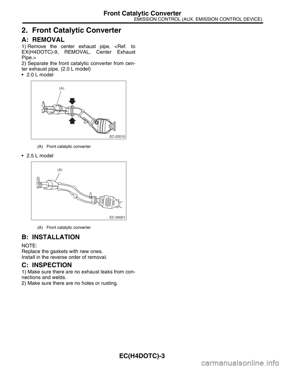
2. Front Catalytic Converter
A: REMOVAL
1) Remove the center exhaust pipe.
Pipe.>
2) Separate the front catalytic converter from cen-
ter exhaust pipe. (2.0 L model)
2.0 L model
2.5 L model
B: INSTALLATION
NOTE:
Replace the gaskets with new ones.
Install in the reverse order of removal.
C: INSPECTION
1) Make sure there are no exhaust leaks from con-
nections and welds.
2) Make sure there are no holes or rusting.
(A) Front catalytic converter
(A) Front catalytic converter
(A)
EC-02010
EC-00001
(A)
Page 1434 of 2870
EC(H4DOTC)-4
EMISSION CONTROL (AUX. EMISSION CONTROL DEVICE)
Rear Catalytic Converter
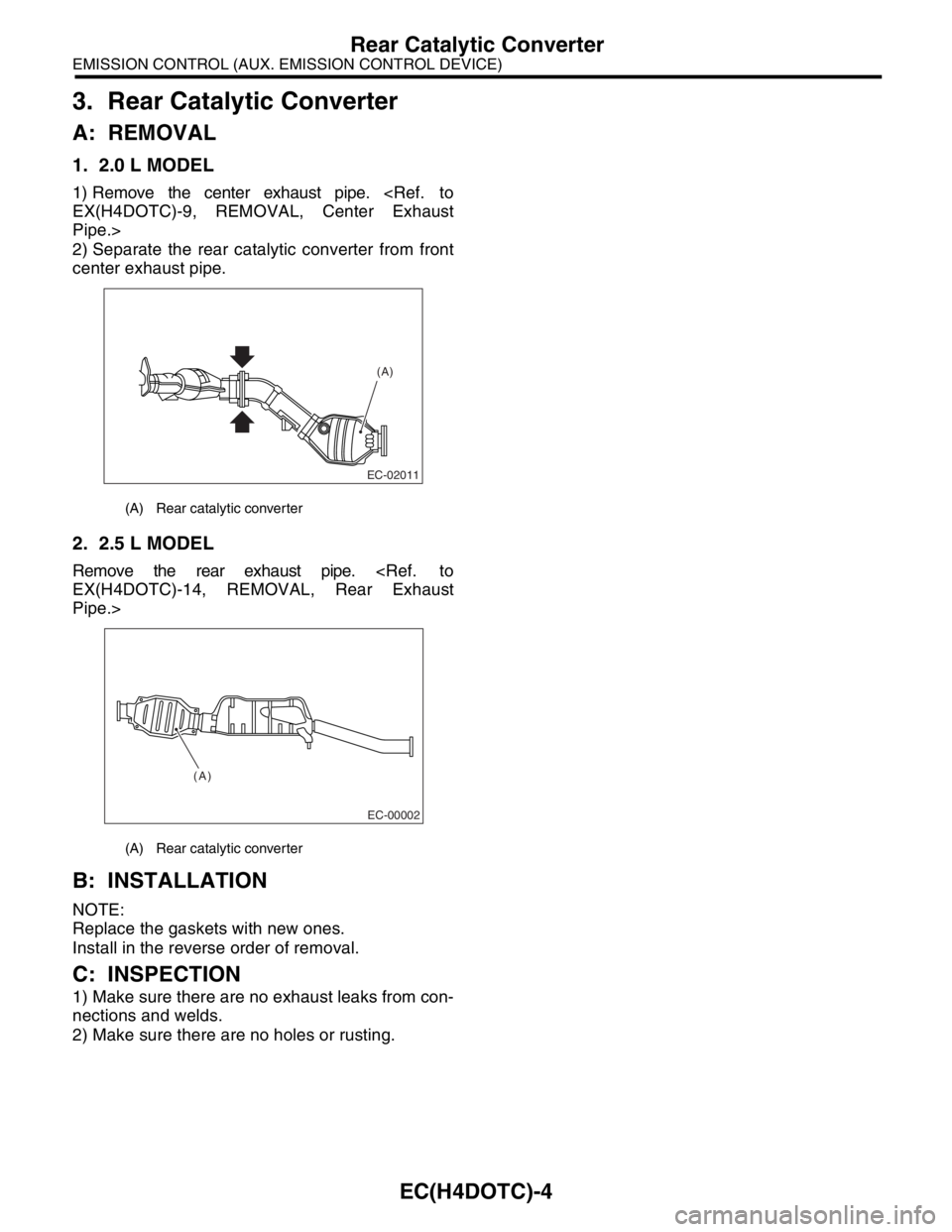
3. Rear Catalytic Converter
A: REMOVAL
1. 2.0 L MODEL
1) Remove the center exhaust pipe.
Pipe.>
2) Separate the rear catalytic converter from front
center exhaust pipe.
2. 2.5 L MODEL
Remove the rear exhaust pipe.
Pipe.>
B: INSTALLATION
NOTE:
Replace the gaskets with new ones.
Install in the reverse order of removal.
C: INSPECTION
1) Make sure there are no exhaust leaks from con-
nections and welds.
2) Make sure there are no holes or rusting.
(A) Rear catalytic converter
(A) Rear catalytic converter
(A)
EC-02011
(A)
EC-00002
Page 1435 of 2870
EC(H4DOTC)-5
EMISSION CONTROL (AUX. EMISSION CONTROL DEVICE)
Precatalytic Converter
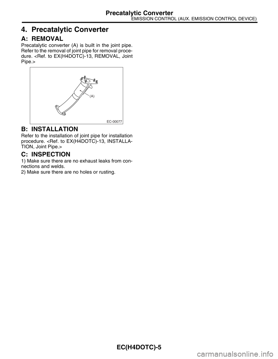
4. Precatalytic Converter
A: REMOVAL
Precatalytic converter (A) is built in the joint pipe.
Refer to the removal of joint pipe for removal proce-
dure.
B: INSTALLATION
Refer to the installation of joint pipe for installation
procedure.
C: INSPECTION
1) Make sure there are no exhaust leaks from con-
nections and welds.
2) Make sure there are no holes or rusting.
(A)
EC-00077
Page 1589 of 2870

EX(H4DOTC)-3
EXHAUST
General Description
(1) Gasket (12) Exhaust manifold upper cover
(LH)Tightening torque: N·m (kgf-m, ft-lb)
(2) Exhaust manifold upper cover
(RH)T1: 19 (1.9, 13.7)
(13) Exhaust manifold lower cover (LH)T2: 7.5 (0.8, 5.5)
(3) Exhaust manifold (RH) (14) GasketT3: 35 (3.6, 26.0)
(4) Exhaust manifold lower cover
(RH)(15) Turbocharger joint pipeT4: 40 (4, 28.9)
(16) GasketT5:
(A/F) Sensor.> or
INSTALLATION, Front Oxygen
(A/F) Sensor.> (5) Front exhaust pipe upper cover (17) Front oxygen (A/F) sensor
(6) Front exhaust pipe upper insulator
(RH)(18) Exhaust temperature sensor
(19) Precatalytic converter
(7) Gasket (20) Front exhaust pipe upper insulator
(LH)
(8) Front exhaust pipeT6:
Temperature Sensor.> or
INSTALLATION, Exhaust
Temperature Sensor.> (9) Front exhaust pipe lower insulator
(RH)(21) Front exhaust pipe lower insulator
(LH)
(10) Front exhaust pipe lower cover (22) Exhaust manifold (LH)
(11) Gasket
Page 1590 of 2870
EX(H4DOTC)-4
EXHAUST
General Description
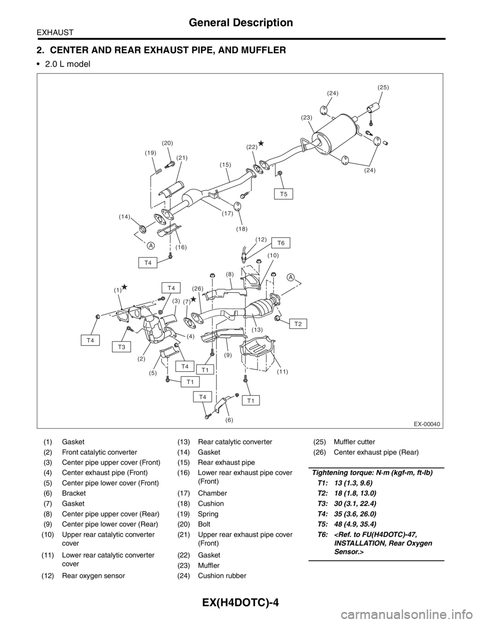
2. CENTER AND REAR EXHAUST PIPE, AND MUFFLER
2.0 L model
(1) Gasket (13) Rear catalytic converter (25) Muffler cutter
(2) Front catalytic converter (14) Gasket (26) Center exhaust pipe (Rear)
(3) Center pipe upper cover (Front) (15) Rear exhaust pipe
(4) Center exhaust pipe (Front) (16) Lower rear exhaust pipe cover
(Front)Tightening torque: N·m (kgf-m, ft-lb)
(5) Center pipe lower cover (Front)T1: 13 (1.3, 9.6)
(6) Bracket (17) ChamberT2: 18 (1.8, 13.0)
(7) Gasket (18) CushionT3: 30 (3.1, 22.4)
(8) Center pipe upper cover (Rear) (19) SpringT4: 35 (3.6, 26.0)
(9) Center pipe lower cover (Rear) (20) BoltT5: 48 (4.9, 35.4)
(10) Upper rear catalytic converter
cover(21) Upper rear exhaust pipe cover
(Front)T6:
Sensor.>
(11) Lower rear catalytic converter
cover(22) Gasket
(23) Muffler
(12) Rear oxygen sensor (24) Cushion rubber
EX-00040
T4
A
T1
T5
T6
T4
(25)
(19)(24)
(24) (20)
(18) (17)
(16)(23)
(22)
(21)
A
(14)
T3
T4
T4
T4
(1)
(2)
(6)
(3)
(5)
T2 (8)(10) (12)
(11) (13)
(9) (26)
(7)
T1
T1
(15)
(4)
Page 1591 of 2870
EX(H4DOTC)-5
EXHAUST
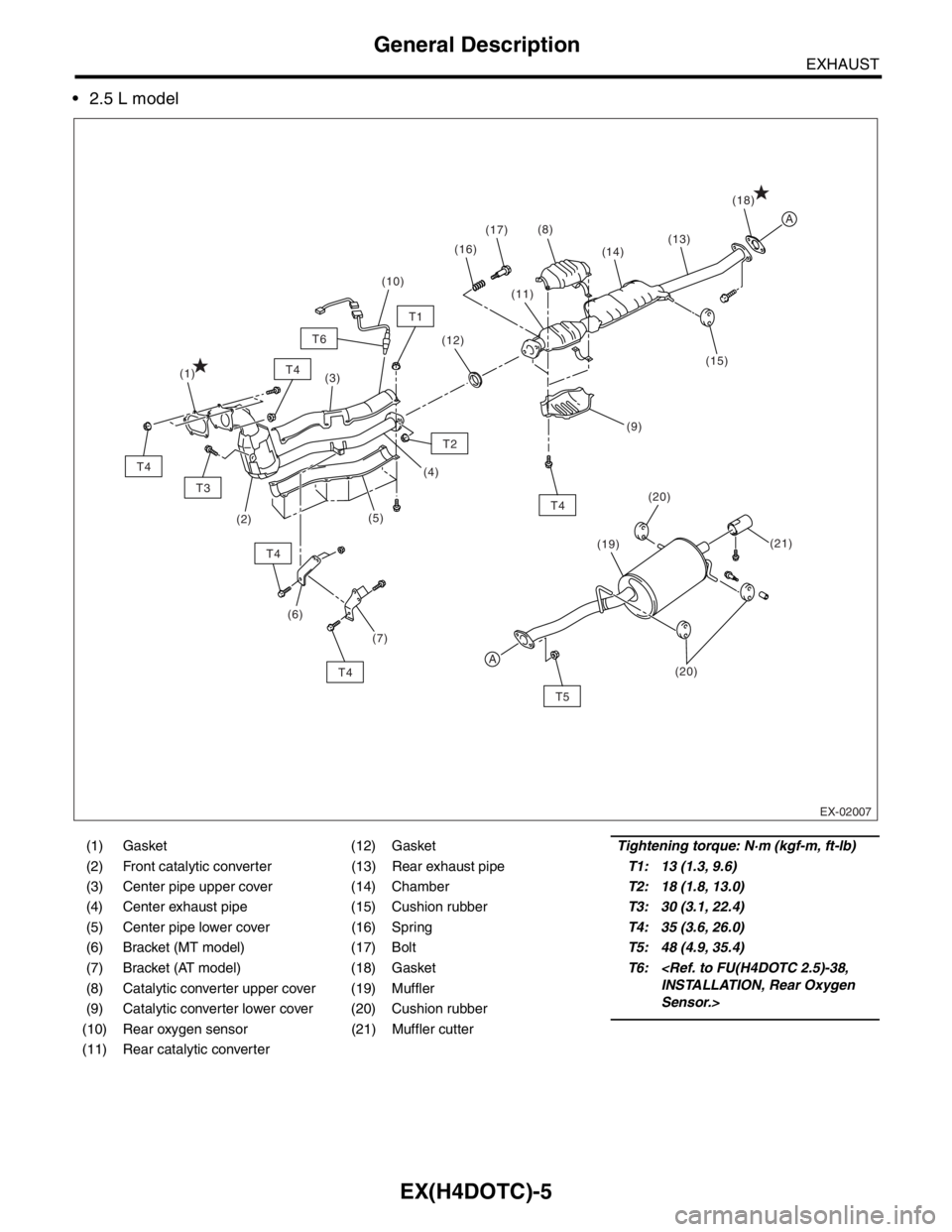
General Description
2.5 L model
(1) Gasket (12) GasketTightening torque: N·m (kgf-m, ft-lb)
(2) Front catalytic converter (13) Rear exhaust pipeT1: 13 (1.3, 9.6)
(3) Center pipe upper cover (14) ChamberT2: 18 (1.8, 13.0)
(4) Center exhaust pipe (15) Cushion rubberT3: 30 (3.1, 22.4)
(5) Center pipe lower cover (16) SpringT4: 35 (3.6, 26.0)
(6) Bracket (MT model) (17) BoltT5: 48 (4.9, 35.4)
(7) Bracket (AT model) (18) GasketT6:
Sensor.> (8) Catalytic converter upper cover (19) Muffler
(9) Catalytic converter lower cover (20) Cushion rubber
(10) Rear oxygen sensor (21) Muffler cutter
(11) Rear catalytic converter
A
A
T5
T4
T3
T4
T4
T4
T4
T2
(21) (20)
(19)(18)
(15) (14)
(1)
(2)(3)
(5)
(6)(4)(11) (17)
(16)(8)
(12)
(10)
(13)
T1
T6
(7)
EX-02007
(9)
(20)
Page 1643 of 2870
EN(H4DOTC)-13
ENGINE (DIAGNOSTIC)
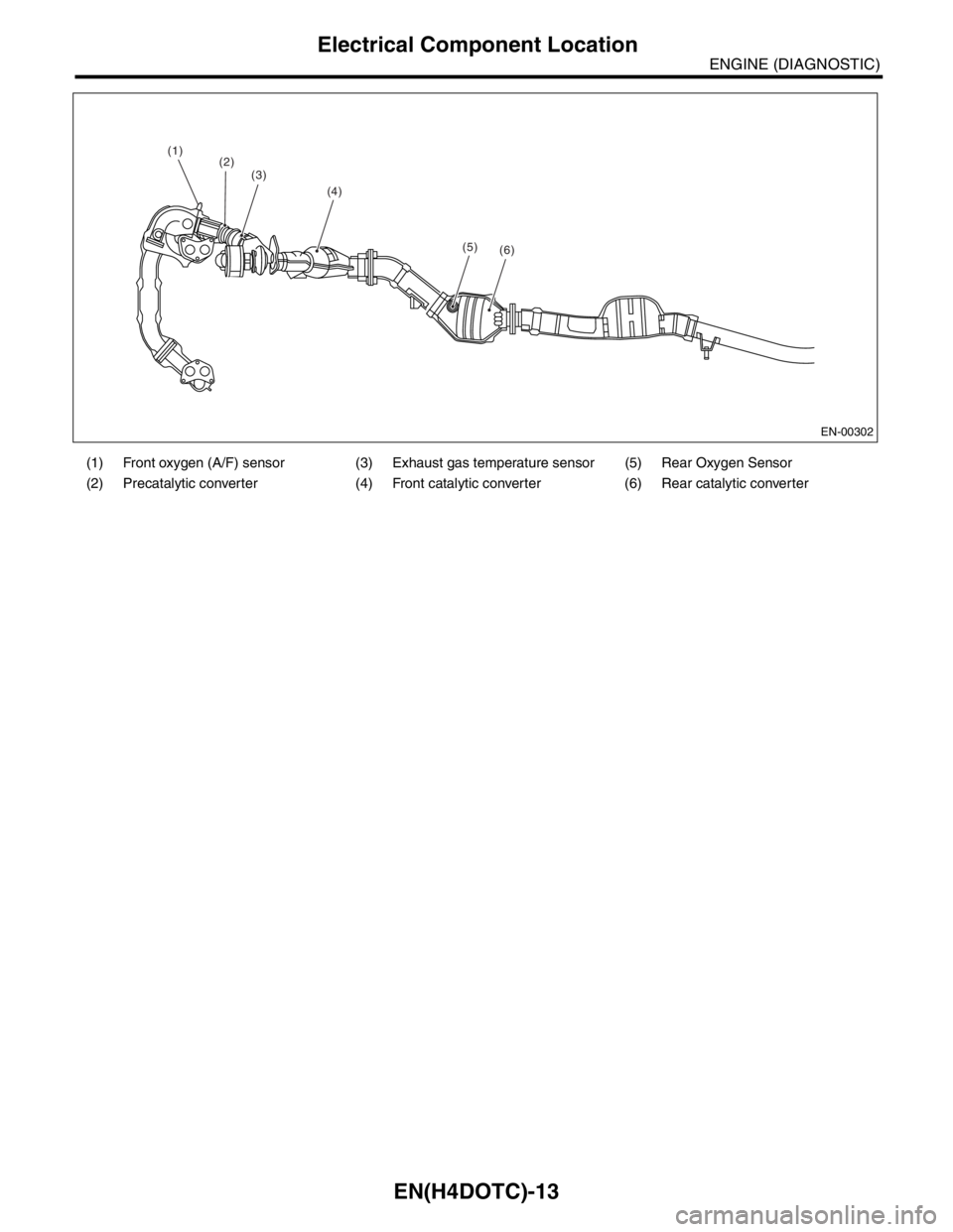
Electrical Component Location
(1) Front oxygen (A/F) sensor (3) Exhaust gas temperature sensor (5) Rear Oxygen Sensor
(2) Precatalytic converter (4) Front catalytic converter (6) Rear catalytic converter
(1)
(4) (3)
(5)(6)
(2)
EN-00302
Page 1771 of 2870

EN(H4DOTC)-138
ENGINE (DIAGNOSTIC)
Diagnostic Procedure with Diagnostic Trouble Code (DTC)
Step Check Yes No
1 CHECK ANY OTHER DTC ON DISPLAY.Is any other DTC displayed? Inspect the rele-
vant DTC using
“List of Diagnostic
Trouble Code
(DTC)”.
List of Diagnostic
Trouble Code
(DTC).>
N
OTE:
In this case, it is
not necessary to
inspect DTC
P0133.Go to step 2.
2 CHECK EXHAUST SYSTEM.
N
OTE:
Check the following items:
Loose installation of front portion of exhaust
pipe onto cylinder heads
Loose connection between front exhaust
pipe and front catalytic converter
Damage of exhaust pipe resulting in a holeIs there a fault in exhaust sys-
tem?Repair exhaust
system.Replace the front
oxygen (A/F) sen-
sor.
Front Oxygen (A/
F) Sensor.>