dimensions SUBARU FORESTER 2004 Service User Guide
[x] Cancel search | Manufacturer: SUBARU, Model Year: 2004, Model line: FORESTER, Model: SUBARU FORESTER 2004Pages: 2870, PDF Size: 38.67 MB
Page 382 of 2870
BS-16
BODY STRUCTURE
Datum Dimensions
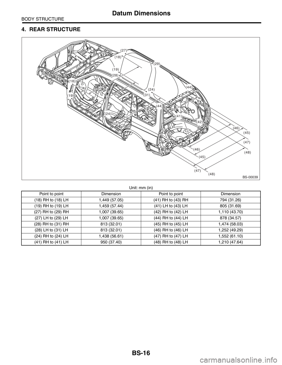
4. REAR STRUCTURE
Unit: mm (in)
Point to point Dimension Point to point Dimension
(18) RH to (18) LH 1,449 (57.05) (41) RH to (43) RH 794 (31.26)
(19) RH to (19) LH 1,459 (57.44) (41) LH to (43) LH 805 (31.69)
(27) RH to (29) RH 1,007 (39.65) (42) RH to (42) LH 1,110 (43.70)
(27) LH to (29) LH 1,007 (39.65) (44) RH to (44) LH 878 (34.57)
(28) RH to (31) RH 813 (32.01) (45) RH to (45) LH 1,474 (58.03)
(28) LH to (31) LH 813 (32.01) (46) RH to (46) LH 1,252 (49.29)
(24) RH to (24) LH 1,438 (56.61) (47) RH to (47) LH 1,552 (61.10)
(41) RH to (41) LH 950 (37.40) (48) RH to (48) LH 1,210 (47.64)
BS-00039(48)(48) (47)
(47) (46)(46)
(45)(45) (18)
(29)
(44)
(41)
(42)
(44)
(31)
(24)
(24)
(28)
(18)
(19)
(27)
(19)
Page 691 of 2870
SPC-2
SPECIFICATION
Forester
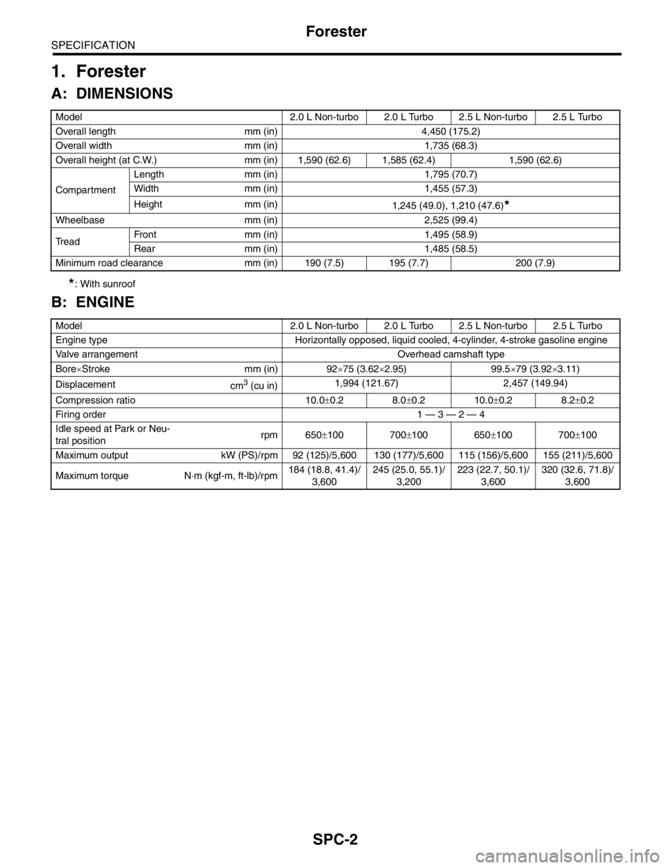
1. Forester
A: DIMENSIONS
★: With sunroof
B: ENGINE
Model 2.0 L Non-turbo 2.0 L Turbo 2.5 L Non-turbo 2.5 L Turbo
Overall length mm (in) 4,450 (175.2)
Overall width mm (in) 1,735 (68.3)
Overall height (at C.W.) mm (in) 1,590 (62.6) 1,585 (62.4) 1,590 (62.6)
CompartmentLength mm (in) 1,795 (70.7)
Width mm (in) 1,455 (57.3)
Height mm (in)
1,245 (49.0), 1,210 (47.6)
★
Wheelbase mm (in) 2,525 (99.4)
Tread Front mm (in) 1,495 (58.9)
Rear mm (in) 1,485 (58.5)
Minimum road clearance mm (in) 190 (7.5) 195 (7.7) 200 (7.9)
Model 2.0 L Non-turbo 2.0 L Turbo 2.5 L Non-turbo 2.5 L Turbo
Engine type Horizontally opposed, liquid cooled, 4-cylinder, 4-stroke gasoline engine
Valve arrangement Overhead camshaft type
Bore×Stroke mm (in) 92×75 (3.62×2.95) 99.5×79 (3.92×3.11)
Displacement
cm
3 (cu in)1,994 (121.67) 2,457 (149.94)
Compression ratio 10.0±0.2 8.0±0.2 10.0±0.2 8.2±0.2
Firing order 1 — 3 — 2 — 4
Idle speed at Park or Neu-
tral positionrpm 650±100 700±100 650±100 700±100
Maximum output kW (PS)/rpm 92 (125)/5,600 130 (177)/5,600 115 (156)/5,600 155 (211)/5,600
Maximum torque N⋅m (kgf-m, ft-lb)/rpm184 (18.8, 41.4)/
3,600245 (25.0, 55.1)/
3,200223 (22.7, 50.1)/
3,600320 (32.6, 71.8)/
3,600
Page 959 of 2870
ME(H4SO)-88
MECHANICAL
Cylinder Block
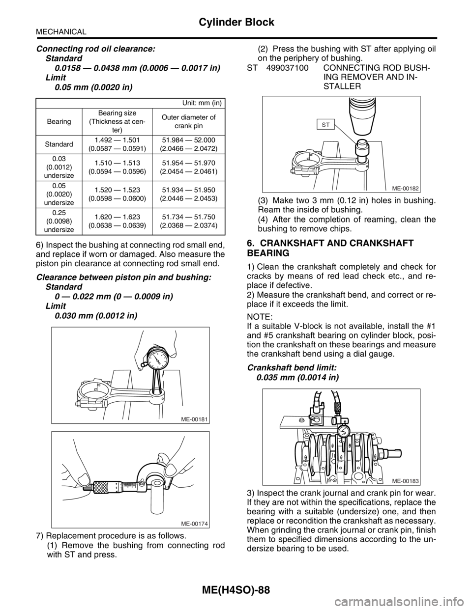
Connecting rod oil clearance:
Standard
0.0158 — 0.0438 mm (0.0006 — 0.0017 in)
Limit
0.05 mm (0.0020 in)
6) Inspect the bushing at connecting rod small end,
and replace if worn or damaged. Also measure the
piston pin clearance at connecting rod small end.
Clearance between piston pin and bushing:
Standard
0 — 0.022 mm (0 — 0.0009 in)
Limit
0.030 mm (0.0012 in)
7) Replacement procedure is as follows.
(1) Remove the bushing from connecting rod
with ST and press.(2) Press the bushing with ST after applying oil
on the periphery of bushing.
ST 499037100 CONNECTING ROD BUSH-
ING REMOVER AND IN-
STALLER
(3) Make two 3 mm (0.12 in) holes in bushing.
Ream the inside of bushing.
(4) After the completion of reaming, clean the
bushing to remove chips.
6. CRANKSHAFT AND CRANKSHAFT
BEARING
1) Clean the crankshaft completely and check for
cracks by means of red lead check etc., and re-
place if defective.
2) Measure the crankshaft bend, and correct or re-
place if it exceeds the limit.
NOTE:
If a suitable V-block is not available, install the #1
and #5 crankshaft bearing on cylinder block, posi-
tion the crankshaft on these bearings and measure
the crankshaft bend using a dial gauge.
Crankshaft bend limit:
0.035 mm (0.0014 in)
3) Inspect the crank journal and crank pin for wear.
If they are not within the specifications, replace the
bearing with a suitable (undersize) one, and then
replace or recondition the crankshaft as necessary.
When grinding the crank journal or crank pin, finish
them to specified dimensions according to the un-
dersize bearing to be used.
Unit: mm (in)
BearingBearing size
(Thickness at cen-
ter)Outer diameter of
crank pin
Standard1.492 — 1.501
(0.0587 — 0.0591)51.984 — 52.000
(2.0466 — 2.0472)
0.03
(0.0012)
undersize1.510 — 1.513
(0.0594 — 0.0596)51.954 — 51.970
(2.0454 — 2.0461)
0.05
(0.0020)
undersize1.520 — 1.523
(0.0598 — 0.0600)51.934 — 51.950
(2.0446 — 2.0453)
0.25
(0.0098)
undersize1.620 — 1.623
(0.0638 — 0.0639)51.734 — 51.750
(2.0368 — 2.0374)
ME-00181
ME-00174
ME-00182
ST
ME-00183
Page 986 of 2870
CO(H4SO)-3
COOLING
General Description
★1: For option code, refer to ID section.
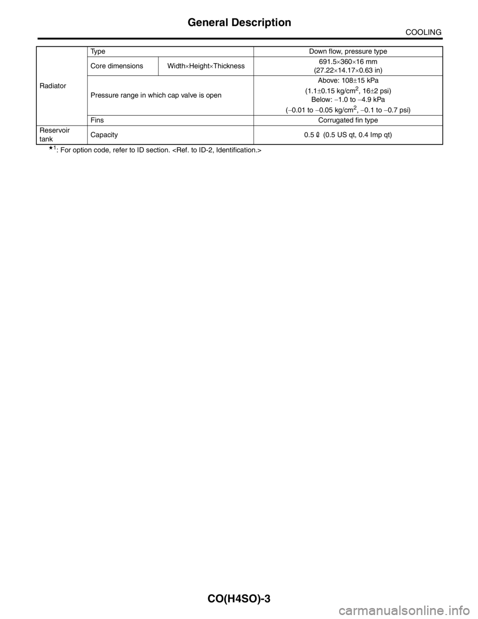
Core dimensions Width×Height×Thickness691.5×360×16 mm
(27.22×14.17×0.63 in)
Pressure range in which cap valve is openAbove: 108±15 kPa
(1.1±0.15 kg/cm
2, 16±2 psi)
Below: −1.0 to −4.9 kPa
(−0.01 to −0.05 kg/cm
2, −0.1 to −0.7 psi)
Fins Corrugated fin type
Reservoir
tankCapacity 0.52 (0.5 US qt, 0.4 Imp qt)
Page 1571 of 2870
ME(H4DOTC)-111
MECHANICAL
Cylinder Block
7) Replacement procedure is as follows:
(1) Remove the bushing from connecting rod
with ST and press.
(2) Press the bushing with ST after applying oil
on the periphery of bushing.
ST 499037100 CONNECTING ROD BUSH-
ING REMOVER AND IN-
STALLER
(3) Make two 3 mm (0.12 in) holes in bushing.
Ream the inside of bushing.
(4) After the completion of reaming, clean the
bushing to remove chips.
6. CRANKSHAFT AND CRANKSHAFT
BEARING
1) Clean the crankshaft completely and check for
cracks by means of red lead check etc., and re-
place if defective.
2) Measure the crankshaft bend, and correct or re-
place if it exceeds the limit.
NOTE:
If a suitable V-block is not available, install the #1
and #5 crankshaft bearing on cylinder block, posi-
tion the crankshaft on these bearings and measure
the crankshaft bend using a dial gauge.
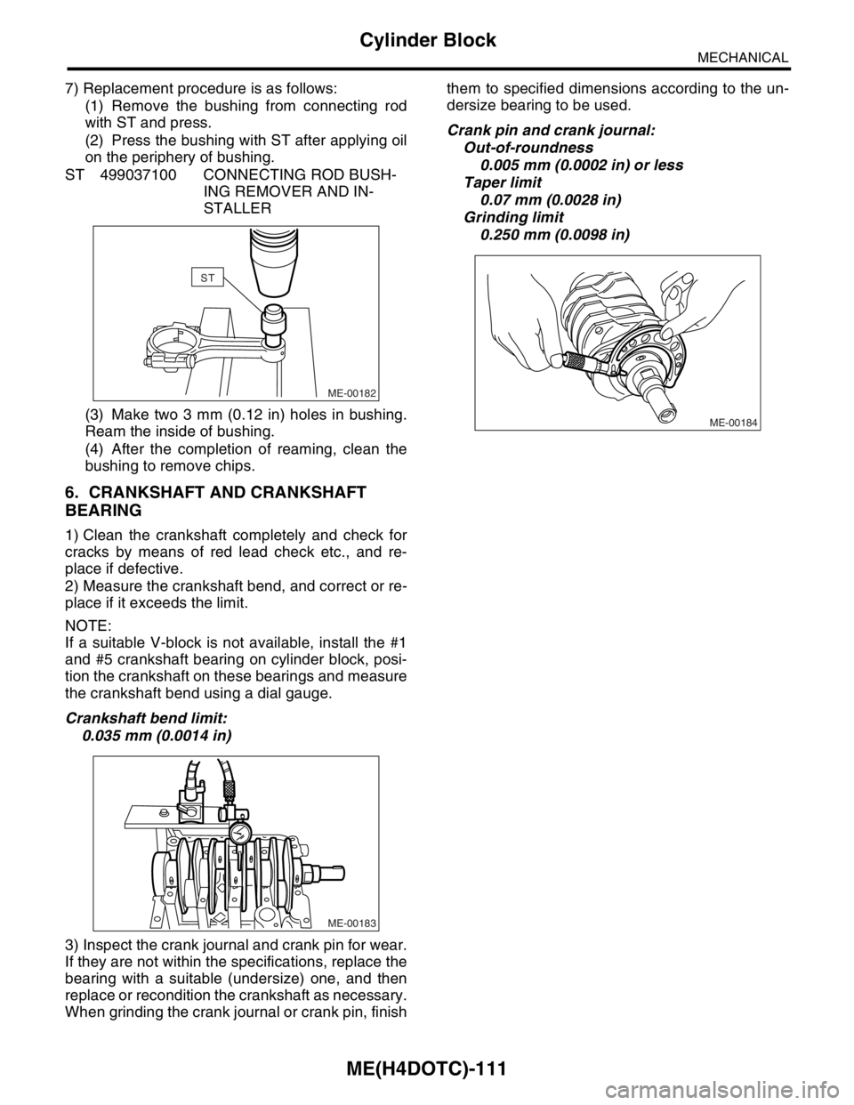
Crankshaft bend limit:
0.035 mm (0.0014 in)
3) Inspect the crank journal and crank pin for wear.
If they are not within the specifications, replace the
bearing with a suitable (undersize) one, and then
replace or recondition the crankshaft as necessary.
When grinding the crank journal or crank pin, finishthem to specified dimensions according to the un-
dersize bearing to be used.
Crank pin and crank journal:
Out-of-roundness
0.005 mm (0.0002 in) or less
Taper limit
0.07 mm (0.0028 in)
Grinding limit
0.250 mm (0.0098 in)
ME-00182
ST
ME-00183
ME-00184