fuel pump SUBARU FORESTER 2004 Service User Guide
[x] Cancel search | Manufacturer: SUBARU, Model Year: 2004, Model line: FORESTER, Model: SUBARU FORESTER 2004Pages: 2870, PDF Size: 38.67 MB
Page 828 of 2870

FU(H4SO)-46
FUEL INJECTION (FUEL SYSTEM)
Fuel Pump Relay
18.Fuel Pump Relay
A: REMOVAL
1) Disconnect the ground cable from battery.
2) Remove the passenger’s side front side sill cov-
er.
3) Remove the bolt which holds fuel pump relay
bracket on the body.
4) Disconnect the connector from the fuel pump.
5) Remove the fuel pump relay from the mounting
bracket.
B: INSTALLATION
Install in the reverse order of removal.
FU-00009
FU-00262
Page 829 of 2870

FU(H4SO)-47
FUEL INJECTION (FUEL SYSTEM)
Fuel
19.Fuel
A: OPERATION
1. RELEASING OF FUEL PRESSURE
WARNING:
Place “NO FIRE” signs near the working area.
Be careful not to spill fuel.
1) Disconnect the connector from fuel pump relay.
2) Start the engine and run it until it stalls.
3) After the engine stalls, crank it for 5 more sec-
onds.
4) Turn the ignition switch to OFF.
2. DRAINING FUEL
WARNING:
Place “NO FIRE” signs near the working area.
Be careful not to spill fuel.
1) Set the vehicle on a lift.
2) Disconnect the ground cable from battery.
3) Open the fuel filler flap lid and remove fuel filler
cap.
4) Lift-up the vehicle.5) Drain fuel from the fuel tank.
Set a container under the vehicle and remove the
drain plug from fuel tank.
6) Tighten the fuel drain plug.
Tightening torque:
26 N
⋅m (2.7 kgf-m, 19.2 ft-lb)
FU-00262
FU-00009
FU-00089
FU-00089
Page 832 of 2870
FU(H4SO)-50
FUEL INJECTION (FUEL SYSTEM)
Fuel Tank
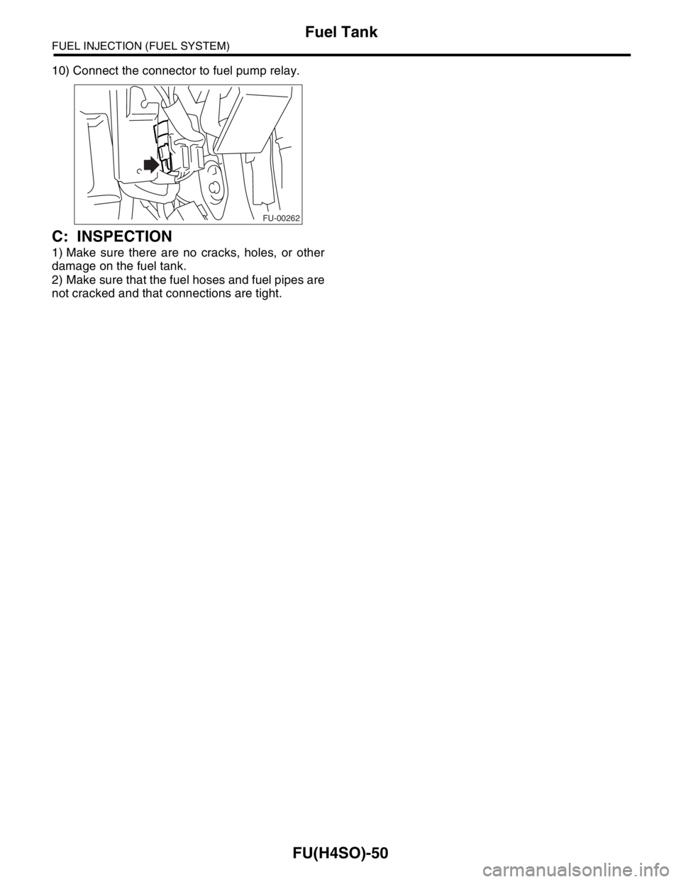
10) Connect the connector to fuel pump relay.
C: INSPECTION
1) Make sure there are no cracks, holes, or other
damage on the fuel tank.
2) Make sure that the fuel hoses and fuel pipes are
not cracked and that connections are tight.
FU-00262
Page 835 of 2870
FU(H4SO)-53
FUEL INJECTION (FUEL SYSTEM)
Fuel Filler Pipe
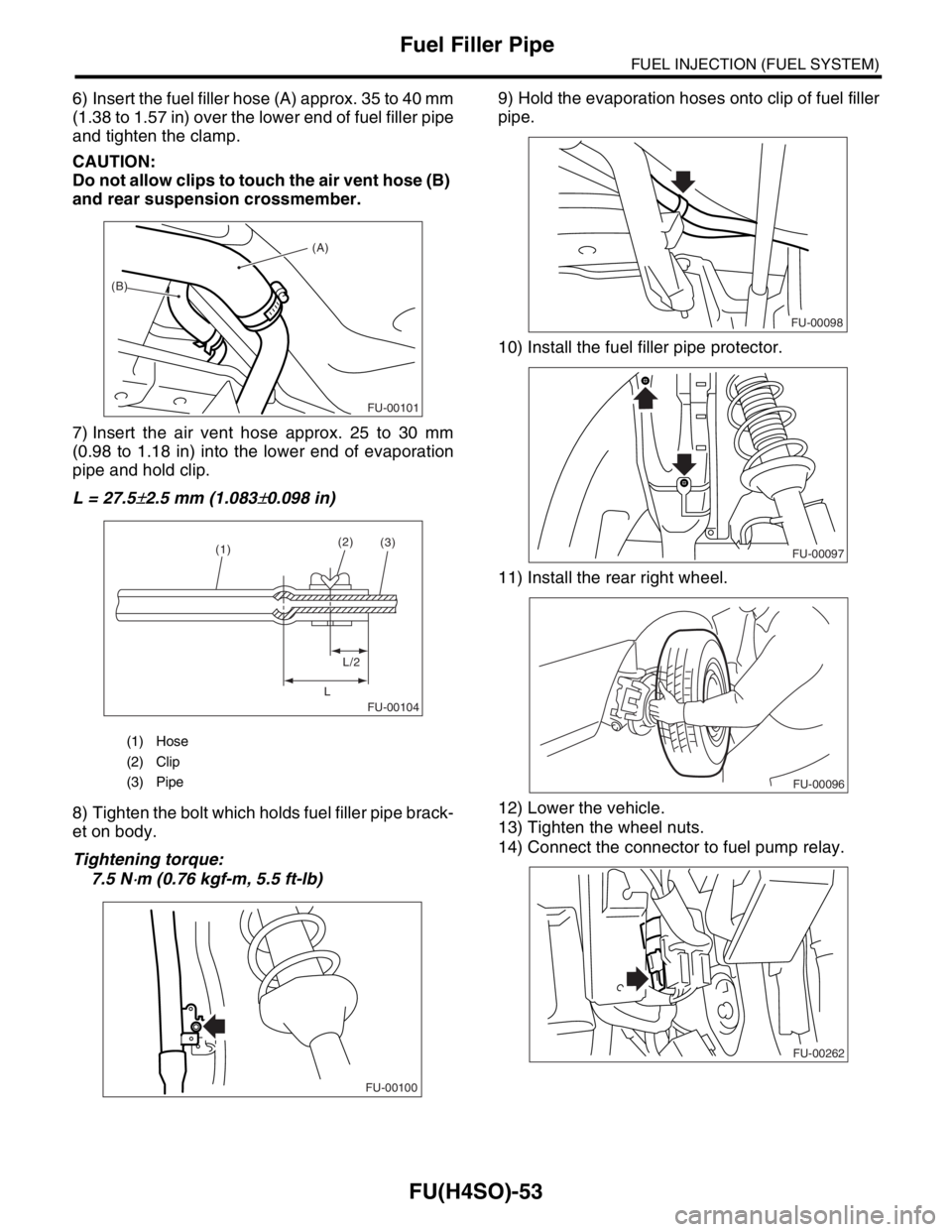
6) Insert the fuel filler hose (A) approx. 35 to 40 mm
(1.38 to 1.57 in) over the lower end of fuel filler pipe
and tighten the clamp.
CAUTION:
Do not allow clips to touch the air vent hose (B)
and rear suspension crossmember.
7) Insert the air vent hose approx. 25 to 30 mm
(0.98 to 1.18 in) into the lower end of evaporation
pipe and hold clip.
L = 27.5
±2.5 mm (1.083±0.098 in)
8) Tighten the bolt which holds fuel filler pipe brack-
et on body.
Tightening torque:
7.5 N
⋅m (0.76 kgf-m, 5.5 ft-lb)9) Hold the evaporation hoses onto clip of fuel filler
pipe.
10) Install the fuel filler pipe protector.
11) Install the rear right wheel.
12) Lower the vehicle.
13) Tighten the wheel nuts.
14) Connect the connector to fuel pump relay.
(1) Hose
(2) Clip
(3) Pipe
(A)
(B)
FU-00101
FU-00104
(1)(2)
L/2
L(3)
FU-00100
FU-00098
FU-00097
FU-00096
FU-00262
Page 837 of 2870
FU(H4SO)-55
FUEL INJECTION (FUEL SYSTEM)
Fuel Pump
22.Fuel Pump
A: REMOVAL
WARNING:
Place “NO FIRE” signs near the working area.
Be careful not to spill fuel.
NOTE:
Fuel pump assembly consists of fuel pump and fuel
level sensor.
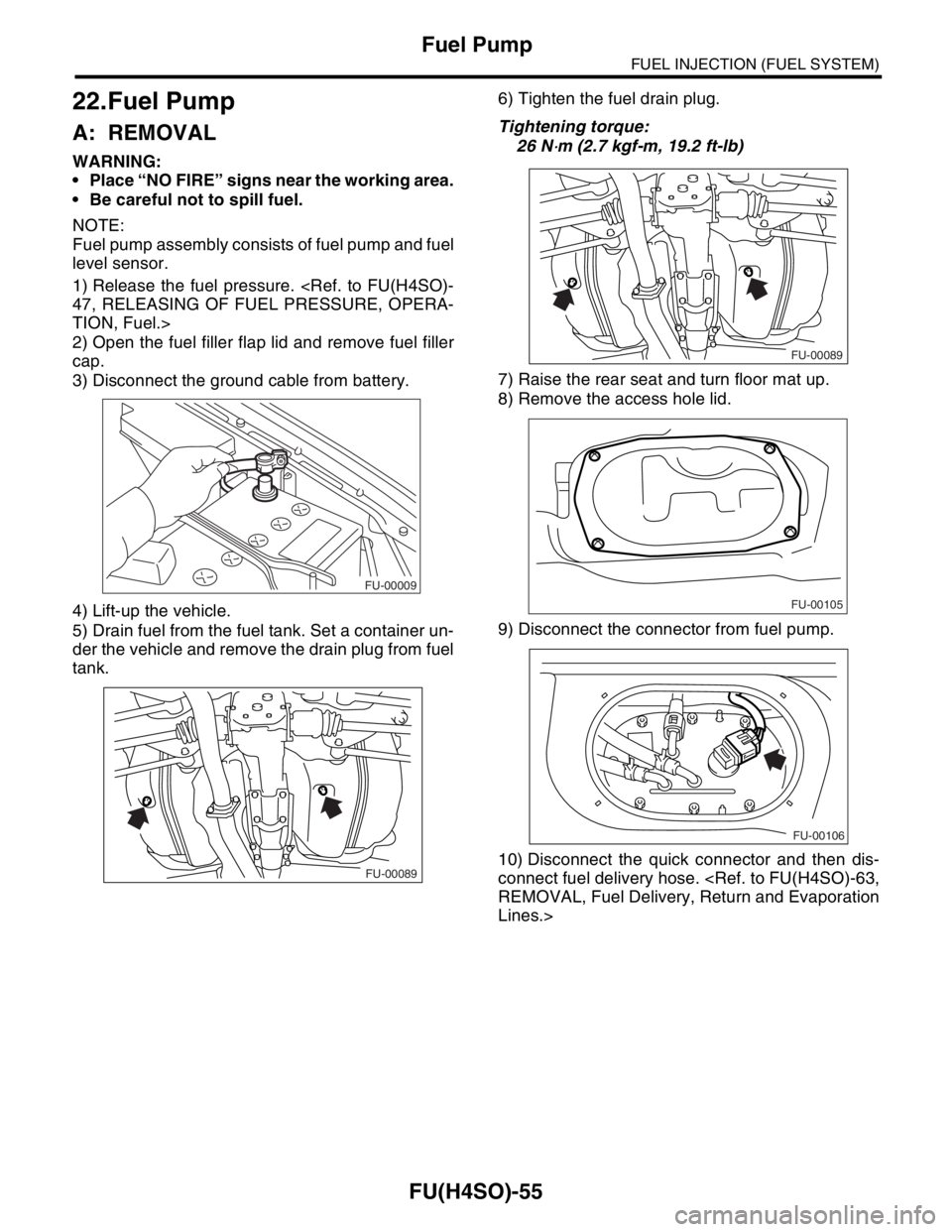
1) Release the fuel pressure.
TION, Fuel.>
2) Open the fuel filler flap lid and remove fuel filler
cap.
3) Disconnect the ground cable from battery.
4) Lift-up the vehicle.
5) Drain fuel from the fuel tank. Set a container un-
der the vehicle and remove the drain plug from fuel
tank.6) Tighten the fuel drain plug.
Tightening torque:
26 N
⋅m (2.7 kgf-m, 19.2 ft-lb)
7) Raise the rear seat and turn floor mat up.
8) Remove the access hole lid.
9) Disconnect the connector from fuel pump.
10) Disconnect the quick connector and then dis-
connect fuel delivery hose.
Lines.>
FU-00009
FU-00089
FU-00089
FU-00105
FU-00106
Page 838 of 2870
FU(H4SO)-56
FUEL INJECTION (FUEL SYSTEM)
Fuel Pump
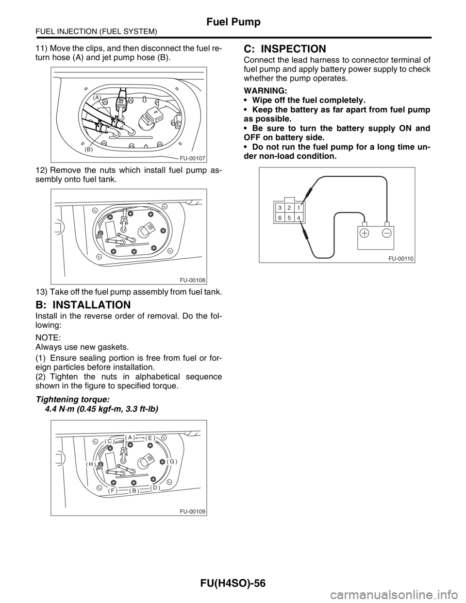
11) Move the clips, and then disconnect the fuel re-
turn hose (A) and jet pump hose (B).
12) Remove the nuts which install fuel pump as-
sembly onto fuel tank.
13) Take off the fuel pump assembly from fuel tank.
B: INSTALLATION
Install in the reverse order of removal. Do the fol-
lowing:
NOTE:
Always use new gaskets.
(1) Ensure sealing portion is free from fuel or for-
eign particles before installation.
(2) Tighten the nuts in alphabetical sequence
shown in the figure to specified torque.
Tightening torque:
4.4 N
⋅m (0.45 kgf-m, 3.3 ft-lb)
C: INSPECTION
Connect the lead harness to connector terminal of
fuel pump and apply battery power supply to check
whether the pump operates.
WARNING:
Wipe off the fuel completely.
Keep the battery as far apart from fuel pump
as possible.
Be sure to turn the battery supply ON and
OFF on battery side.
Do not run the fuel pump for a long time un-
der non-load condition.
FU-00107
(B)(A)
FU-00108
FU-00109
(A)
(B)
(C)
(D)
(E)
(F)
(G)(H)FU-00110
1 2 3
4 5 6
Page 839 of 2870
FU(H4SO)-57
FUEL INJECTION (FUEL SYSTEM)
Fuel Level Sensor
23.Fuel Level Sensor
A: REMOVAL
WARNING:
Place “NO FIRE” signs near the working area.
Be careful not to spill fuel.
NOTE:
Fuel level sensor is built in fuel pump assembly.
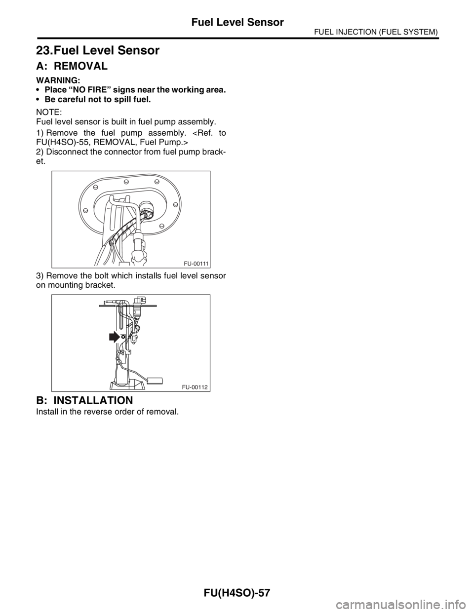
1) Remove the fuel pump assembly.
2) Disconnect the connector from fuel pump brack-
et.
3) Remove the bolt which installs fuel level sensor
on mounting bracket.
B: INSTALLATION
Install in the reverse order of removal.
FU-00111
FU-00112
Page 840 of 2870
FU(H4SO)-58
FUEL INJECTION (FUEL SYSTEM)
Fuel Sub Level Sensor
24.Fuel Sub Level Sensor
A: REMOVAL
WARNING:
Place “NO FIRE” signs near the working area.
Be careful not to spill fuel.
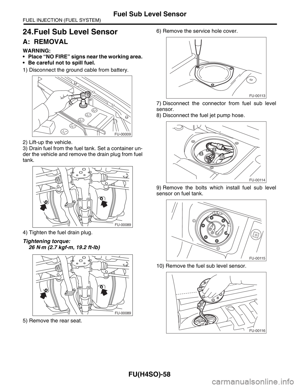
1) Disconnect the ground cable from battery.
2) Lift-up the vehicle.
3) Drain fuel from the fuel tank. Set a container un-
der the vehicle and remove the drain plug from fuel
tank.
4) Tighten the fuel drain plug.
Tightening torque:
26 N
⋅m (2.7 kgf-m, 19.2 ft-lb)
5) Remove the rear seat.6) Remove the service hole cover.
7) Disconnect the connector from fuel sub level
sensor.
8) Disconnect the fuel jet pump hose.
9) Remove the bolts which install fuel sub level
sensor on fuel tank.
10) Remove the fuel sub level sensor.
FU-00009
FU-00089
FU-00089
FU-00113
FU-00114
FU-00115
FU-00116
Page 848 of 2870
FU(H4SO)-66
FUEL INJECTION (FUEL SYSTEM)
Fuel System Trouble in General
29.Fuel System Trouble in General
A: INSPECTION
NOTE:
When the vehicle is left unattended for an ex-
tended period of time, water may accumulate in the
fuel tank.
To prevent water condensation.
(1) Top off the fuel tank or drain the fuel com-
pletely.
(2) Drain the water condensation from the fuel
filter.
Refilling the fuel tank.
Refill the fuel tank while there is still some fuel left in
the tank.
Protecting the fuel system against freezing and
water condensation.
(3) Cold areas :
In snow-covered areas, mountainous areas, ski-
ing areas, etc. where ambient temperatures
drop below 0°C (32°F) throughout the winter
season, use an anti-freeze solution in the fuel
tank. Refueling will also complement the effect
of anti-freeze solution each time the fuel leveldrops to about one-half. After the winter season,
drain the water which may have accumulated in
the fuel filter and fuel tank in the manner same
as that described under “Affected areas” below.
(4) Affected areas :
When the water condensation is notched in the
fuel filter, drain the water from both the fuel filter
and fuel tank or use a water removing agent (or
anti-freeze solution) in the fuel tank.
Observe the instructions, notes, etc., indicated
on the label affixed to the anti-freeze solution (wa-
ter removing agent) container before use.
Trouble and possible cause Corrective action
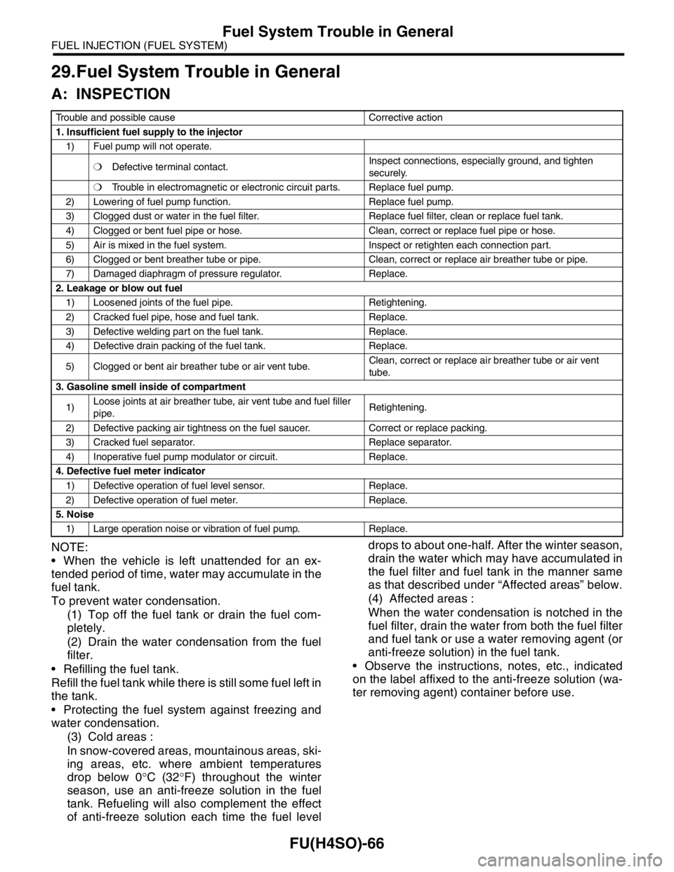
1. Insufficient fuel supply to the injector
1) Fuel pump will not operate.
❍Defective terminal contact.Inspect connections, especially ground, and tighten
securely.
❍Trouble in electromagnetic or electronic circuit parts. Replace fuel pump.
2) Lowering of fuel pump function. Replace fuel pump.
3) Clogged dust or water in the fuel filter. Replace fuel filter, clean or replace fuel tank.
4) Clogged or bent fuel pipe or hose. Clean, correct or replace fuel pipe or hose.
5) Air is mixed in the fuel system. Inspect or retighten each connection part.
6) Clogged or bent breather tube or pipe. Clean, correct or replace air breather tube or pipe.
7) Damaged diaphragm of pressure regulator. Replace.
2. Leakage or blow out fuel
1) Loosened joints of the fuel pipe. Retightening.
2) Cracked fuel pipe, hose and fuel tank. Replace.
3) Defective welding part on the fuel tank. Replace.
4) Defective drain packing of the fuel tank. Replace.
5) Clogged or bent air breather tube or air vent tube.Clean, correct or replace air breather tube or air vent
tube.
3. Gasoline smell inside of compartment
1)Loose joints at air breather tube, air vent tube and fuel filler
pipe.Retightening.
2) Defective packing air tightness on the fuel saucer. Correct or replace packing.
3) Cracked fuel separator. Replace separator.
4) Inoperative fuel pump modulator or circuit. Replace.
4. Defective fuel meter indicator
1) Defective operation of fuel level sensor. Replace.
2) Defective operation of fuel meter. Replace.
5. Noise
1) Large operation noise or vibration of fuel pump. Replace.
Page 899 of 2870
ME(H4SO)-30
MECHANICAL
Fuel Pressure
7. Fuel Pressure
A: INSPECTION
WARNING:
Before removing the fuel pressure gauge, re-
lease the fuel pressure.
NOTE:
If out of specification, check or replace the pressure
regulator and pressure regulator vacuum hose.
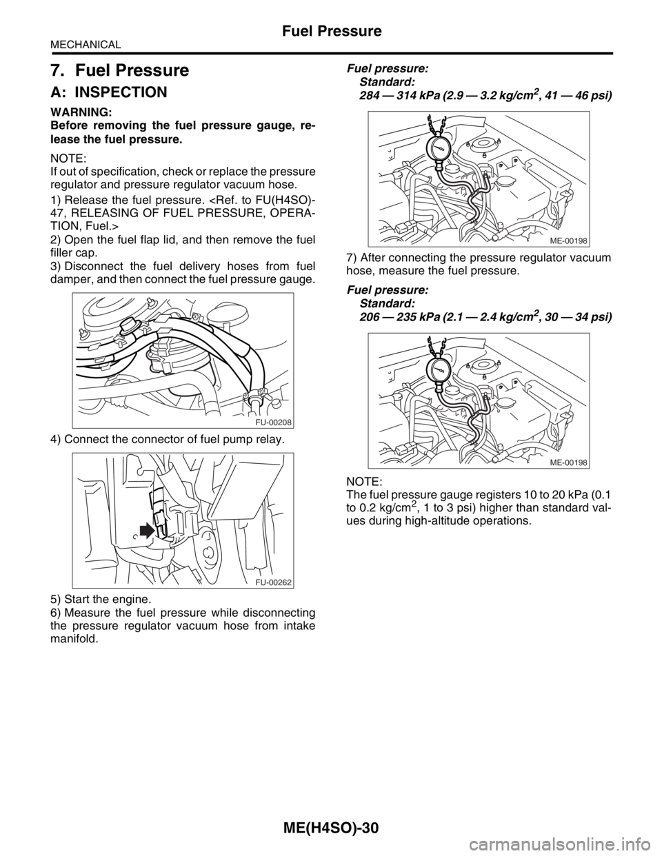
1) Release the fuel pressure.
TION, Fuel.>
2) Open the fuel flap lid, and then remove the fuel
filler cap.
3) Disconnect the fuel delivery hoses from fuel
damper, and then connect the fuel pressure gauge.
4) Connect the connector of fuel pump relay.
5) Start the engine.
6) Measure the fuel pressure while disconnecting
the pressure regulator vacuum hose from intake
manifold.Fuel pressure:
Standard:
284 — 314 kPa (2.9 — 3.2 kg/cm
2, 41 — 46 psi)
7) After connecting the pressure regulator vacuum
hose, measure the fuel pressure.
Fuel pressure:
Standard:
206 — 235 kPa (2.1 — 2.4 kg/cm
2, 30 — 34 psi)
NOTE:
The fuel pressure gauge registers 10 to 20 kPa (0.1
to 0.2 kg/cm
2, 1 to 3 psi) higher than standard val-
ues during high-altitude operations.
FU-00208
FU-00262
ME-00198
ME-00198