gas type SUBARU FORESTER 2004 Service User Guide
[x] Cancel search | Manufacturer: SUBARU, Model Year: 2004, Model line: FORESTER, Model: SUBARU FORESTER 2004Pages: 2870, PDF Size: 38.67 MB
Page 2377 of 2870
4AT-64
AUTOMATIC TRANSMISSION
Control Valve Body
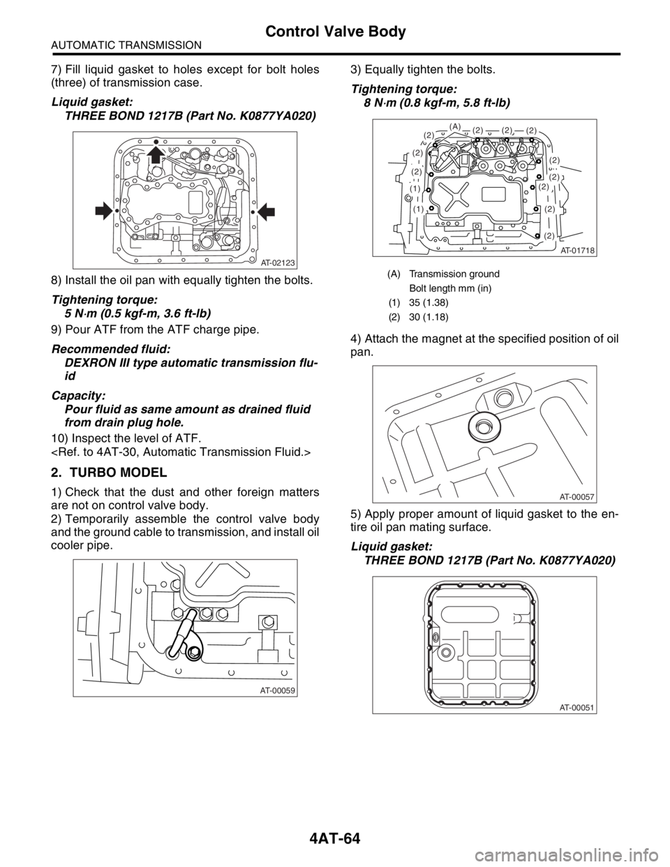
7) Fill liquid gasket to holes except for bolt holes
(three) of transmission case.
Liquid gasket:
THREE BOND 1217B (Part No. K0877YA020)
8) Install the oil pan with equally tighten the bolts.
Tightening torque:
5 N
⋅m (0.5 kgf-m, 3.6 ft-lb)
9) Pour ATF from the ATF charge pipe.
Recommended fluid:
DEXRON III type automatic transmission flu-
id
Capacity:
Pour fluid as same amount as drained fluid
from drain plug hole.
10) Inspect the level of ATF.
2. TURBO MODEL
1) Check that the dust and other foreign matters
are not on control valve body.
2) Temporarily assemble the control valve body
and the ground cable to transmission, and install oil
cooler pipe.3) Equally tighten the bolts.
Tightening torque:
8 N
⋅m (0.8 kgf-m, 5.8 ft-lb)
4) Attach the magnet at the specified position of oil
pan.
5) Apply proper amount of liquid gasket to the en-
tire oil pan mating surface.
Liquid gasket:
THREE BOND 1217B (Part No. K0877YA020)
AT-02123
AT-00059
(A) Transmission ground
Bolt length mm (in)
(1) 35 (1.38)
(2) 30 (1.18)
AT-01718
(1)
(1)
(2)
(2)
(2)(2)
(2)
(2)(2)(2)(2)
(2)
(2)
(A)
AT-00057
AT-00051
Page 2378 of 2870
4AT-65
AUTOMATIC TRANSMISSION
Control Valve Body
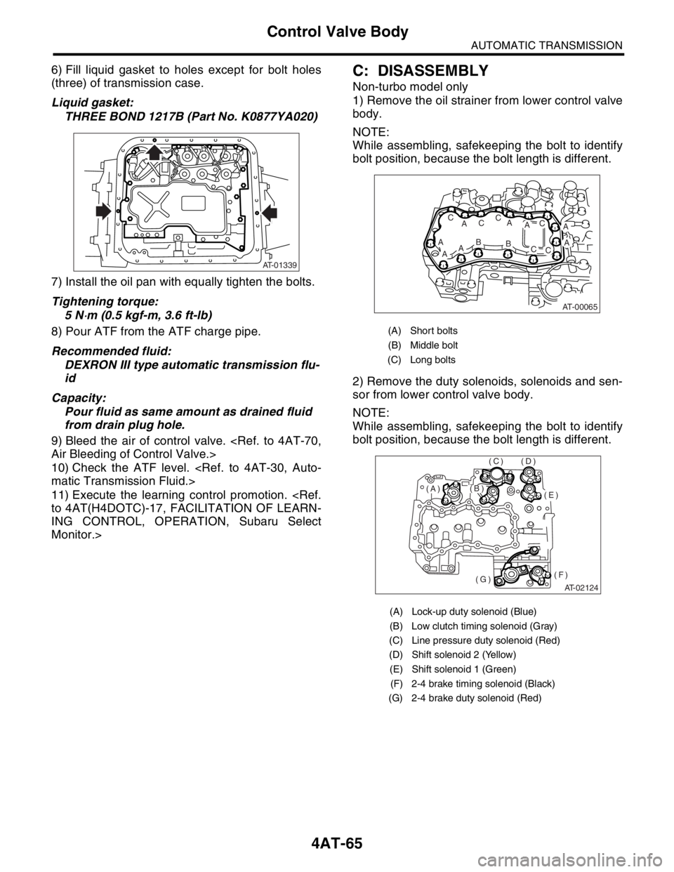
6) Fill liquid gasket to holes except for bolt holes
(three) of transmission case.
Liquid gasket:
THREE BOND 1217B (Part No. K0877YA020)
7) Install the oil pan with equally tighten the bolts.
Tightening torque:
5 N
⋅m (0.5 kgf-m, 3.6 ft-lb)
8) Pour ATF from the ATF charge pipe.
Recommended fluid:
DEXRON III type automatic transmission flu-
id
Capacity:
Pour fluid as same amount as drained fluid
from drain plug hole.
9) Bleed the air of control valve.
10) Check the ATF level.
11) Execute the learning control promotion.
ING CONTROL, OPERATION, Subaru Select
Monitor.>
C: DISASSEMBLY
Non-turbo model only
1) Remove the oil strainer from lower control valve
body.
NOTE:
While assembling, safekeeping the bolt to identify
bolt position, because the bolt length is different.
2) Remove the duty solenoids, solenoids and sen-
sor from lower control valve body.
NOTE:
While assembling, safekeeping the bolt to identify
bolt position, because the bolt length is different.
AT-01339
(A) Short bolts
(B) Middle bolt
(C) Long bolts
(A) Lock-up duty solenoid (Blue)
(B) Low clutch timing solenoid (Gray)
(C) Line pressure duty solenoid (Red)
(D) Shift solenoid 2 (Yellow)
(E) Shift solenoid 1 (Green)
(F) 2-4 brake timing solenoid (Black)
(G) 2-4 brake duty solenoid (Red)
AT-00065
A
ABAA
AC
ACC
AB
AC
CC
AT-02124
(E)
(F)(G)
(D)(C)
(B)(A)
Page 2845 of 2870
CL-19
CLUTCH SYSTEM
Flywheel
3. Flywheel
A: REMOVAL
1) Remove the transmission assembly.
sembly.>
2) Remove the clutch cover and clutch disc.
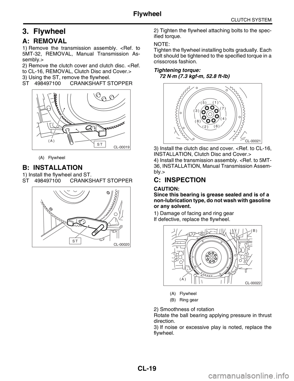
3) Using the ST, remove the flywheel.
ST 498497100 CRANKSHAFT STOPPER
B: INSTALLATION
1) Install the flywheel and ST.
ST 498497100 CRANKSHAFT STOPPER2) Tighten the flywheel attaching bolts to the spec-
ified torque.
NOTE:
Tighten the flywheel installing bolts gradually. Each
bolt should be tightened to the specified torque in a
crisscross fashion.
Tightening torque:
72 N
⋅m (7.3 kgf-m, 52.8 ft-lb)
3) Install the clutch disc and cover.
4) Install the transmission assembly.
bly.>
C: INSPECTION
CAUTION:
Since this bearing is grease sealed and is of a
non-lubrication type, do not wash with gasoline
or any solvent.
1) Damage of facing and ring gear
If defective, replace the flywheel.
2) Smoothness of rotation
Rotate the ball bearing applying pressure in thrust
direction.
3) If noise or excessive play is noted, replace the
flywheel.
(A) Flywheel
CL-00019ST (A)
CL-00020ST
(A) Flywheel
(B) Ring gear
CL-00021
(1)
(2)
(3)
(4)
(5)
(6)
(7)
(8)
CL-00022
(B)
(A)
Page 2848 of 2870
CL-22
CLUTCH SYSTEM
Release Bearing and Lever
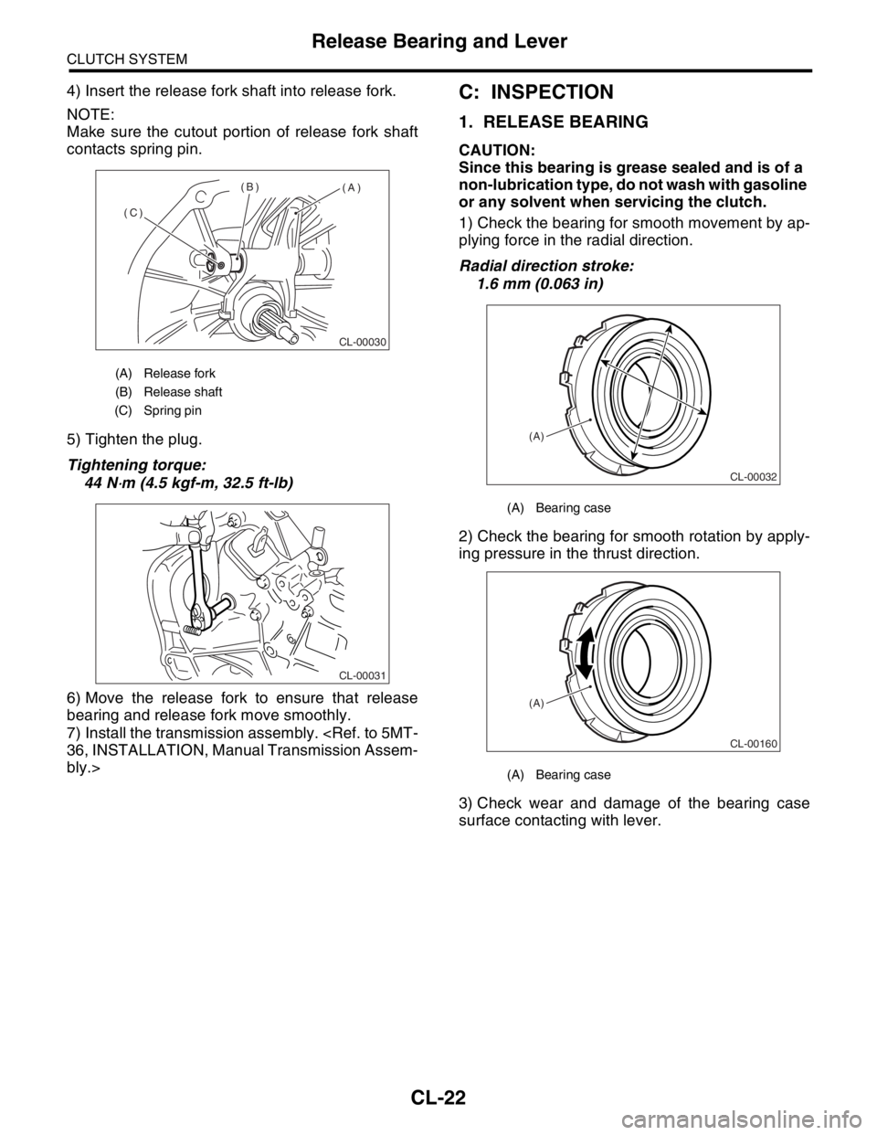
4) Insert the release fork shaft into release fork.
NOTE:
Make sure the cutout portion of release fork shaft
contacts spring pin.
5) Tighten the plug.
Tightening torque:
44 N
⋅m (4.5 kgf-m, 32.5 ft-lb)
6) Move the release fork to ensure that release
bearing and release fork move smoothly.
7) Install the transmission assembly.
bly.>
C: INSPECTION
1. RELEASE BEARING
CAUTION:
Since this bearing is grease sealed and is of a
non-lubrication type, do not wash with gasoline
or any solvent when servicing the clutch.
1) Check the bearing for smooth movement by ap-
plying force in the radial direction.
Radial direction stroke:
1.6 mm (0.063 in)
2) Check the bearing for smooth rotation by apply-
ing pressure in the thrust direction.
3) Check wear and damage of the bearing case
surface contacting with lever.
(A) Release fork
(B) Release shaft
(C) Spring pin
CL-00030
(A) (B)
(C)
CL-00031
(A) Bearing case
(A) Bearing case
CL-00032
(A)
CL-00160
(A)