manual transmission SUBARU FORESTER 2004 Service User Guide
[x] Cancel search | Manufacturer: SUBARU, Model Year: 2004, Model line: FORESTER, Model: SUBARU FORESTER 2004Pages: 2870, PDF Size: 38.67 MB
Page 2312 of 2870
FUJI HEAVY INDUSTRIES LTD. G8080GE5
2004 FORESTER SERVICE MANUAL QUICK REFERENCE INDEX
TRANSMISSION SECTION
This service manual has been prepared
to provide SUBARU service personnel
with the necessary information and data
for the correct maintenance and repair
of SUBARU vehicles.
This manual includes the procedures
for maintenance, disassembling, reas-
sembling, inspection and adjustment of
components and diagnostics for guid-
ance of experienced mechanics.
Please peruse and utilize this manual
fully to ensure complete repair work for
satisfying our customers by keeping
their vehicle in optimum condition.
When replacement of parts during
repair work is needed, be sure to use
SUBARU genuine parts.
All information, illustration and specifi-
cations contained in this manual are
based on the latest product information
available at the time of publication
approval.CONTROL SYSTEM CS
AUTOMATIC TRANSMISSION 4AT
AUTOMATIC TRANSMISSION
(DIAGNOSTIC)4AT(H4SO)
AUTOMATIC TRANSMISSION
(DIAGNOSTIC)4AT(H4DOTC)
AUTOMATIC TRANSMISSION
(DIAGNOSTIC)4AT(H4DOTC 2.5)
MANUAL TRANSMISSION AND
DIFFERENTIAL5MT
CLUTCH SYSTEM CL
Page 2320 of 2870

4AT-8
AUTOMATIC TRANSMISSION
General Description
(1) ATF level gauge (19) Oil filter (41) Transmission case
(2) ATF charger pipe (20) Oil filter stud bolt (42) Plate ASSY
(3) O-ring (21) Drain plug (ATF) (43) Washer
(4) Transfer valve plate (22) Gasket (44) Bushing (turbo model)
(Non-turbo model) (23) Oil pan (45) ATF cooler inlet pipe (model with
ATF cooler (with warmer func-
tion)) (5) Transfer valve ASSY (24) Magnet
(Non-turbo model) (25) Stud bolt (Short)
(6) Transfer clutch seal
(Non-turbo model)(26) Stud bolt (Long) (46) ATF cooler outlet pipe (model
with ATF cooler (with warmer
function)) (27) Parking rod
(7) Transfer duty solenoid (non-turbo
model)(28) Manual plate
(29) Spring pin
(8) Straight pin (30) Detention springTightening torque: N
⋅m (kgf-m, ft-lb)
(9) Return spring (31) BallT1: 3.4 (0.35, 2.6)
(10) Shaft (32) SpringT2: 5 (0.5, 3.6)
(11) Parking pawl (33) GasketT3: 6 (0.6, 4.4)
(12) Parking support (34) ATF cooler outlet pipe (model
without ATF cooler (with warmer
function))T4: 8 (0.8, 6)
(13) Inlet filter (Non-turbo model)T5: 12 (1.2, 8.7)
(14) GasketT6: 13 (1.3, 10)
(15) ATF cooler inlet pipe (model with-
out ATF cooler (with warmer func-
tion))(35) Union screwT7: 14 (1.4, 10)
(36) Oil sealT8: 18 (1.8, 13)
(37) Range select leverT9: 25 (2.5, 18.1)
(16) Union screw (38) Inhibitor switch ASSYT10: 45 (4.6, 33.2)
(17) O-ring (39) NippleT11: 21 (2.1, 15.5)
(18) Test plug (40) Air breather hose
Page 2345 of 2870

4AT-33
AUTOMATIC TRANSMISSION
Stall Test
5. Stall Test
A: INSPECTION
NOTE:
The stall test is of extreme importance in diagnos-
ing the condition of the automatic transmission and
the engine. It should be conducted to measure the
engine stall speeds in “R” and “2” ranges (when
HOLD switch is ON).
Purposes of the stall test:
To check the operation of the automatic trans-
mission clutch.
To check the operation of the torque converter
clutch.
To check engine performance.
1) Check that the throttle valve opens fully.
2) Check that the engine oil level is correct.
3) Check that the coolant level is correct.
4) Check that the ATF level is correct.
5) Check that the differential gear oil level is cor-
rect.
6) Increase ATF temperature to 70 — 80°C (158 —
176°F) by idling the engine for approximately 30
minutes (with select lever set to “N” or “P”).
7) Place the wheel chocks at the front and rear of
all wheels and engage the parking brake.
8) Shift the manual linkage to ensure it operates
properly, then shift the select lever to the “2” range
and turn the HOLD switch to ON.
9) While forcibly depressing the foot brake pedal,
gradually depress the accelerator pedal until the
engine operates at full throttle.
10) When the engine speed is stabilized, record
that speed quickly and release the accelerator ped-
al.
11) Shift the select lever to “N” range, and cool
down the engine by idling it for more than one
minute.12) If the stall speed in “2” range (with HOLD switch
ON) is higher than specifications, low clutch slip-
ping and “2-4 brake slipping” may occur. To identify
it, conduct the same test as above in “R” range.
13) Perform the stall tests with the select lever in
the “D” range.
NOTE:
Do not continue the stall test for more than five
seconds at a time (from closed throttle, fully open
throttle to stall speed reading). Failure to follow this
instruction causes the engine oil and ATF to deteri-
orate and the clutch and brake to be adversely af-
fected.
Be sure to cool down the engine for at least one
minute after each stall test with the select lever set
in the “P” or “N” range and with the idle speed lower
than 1,200 rpm.
If the stall speed is higher than the specified
range, attempt to finish the stall test in as short a
time as possible, in order to prevent the automatic
transmission from sustaining damage.
Stall speed (at sea level):
2.0 L NON-TURBO MODEL
2,000 — 2,500 rpm
2.0 L TURBO MODEL
2,600 — 3,300 rpm
2.5 L NON-TURBO MODEL
2,100 — 2,600 rpm
2.5 L TURBO MODEL
2,700 — 3,200 rpm
(A) Brake pedal
(B) Accelerator pedal
(A) (B)
P
R
N
D
3
2
1
AT-00449
Page 2361 of 2870
FUJI HEAVY INDUSTRIES LTD. G8080GE5
2004 FORESTER SERVICE MANUAL QUICK REFERENCE INDEX
TRANSMISSION SECTION
This service manual has been prepared
to provide SUBARU service personnel
with the necessary information and data
for the correct maintenance and repair
of SUBARU vehicles.
This manual includes the procedures
for maintenance, disassembling, reas-
sembling, inspection and adjustment of
components and diagnostics for guid-
ance of experienced mechanics.
Please peruse and utilize this manual
fully to ensure complete repair work for
satisfying our customers by keeping
their vehicle in optimum condition.
When replacement of parts during
repair work is needed, be sure to use
SUBARU genuine parts.
All information, illustration and specifi-
cations contained in this manual are
based on the latest product information
available at the time of publication
approval.CONTROL SYSTEM CS
AUTOMATIC TRANSMISSION 4AT
AUTOMATIC TRANSMISSION
(DIAGNOSTIC)4AT(H4SO)
AUTOMATIC TRANSMISSION
(DIAGNOSTIC)4AT(H4DOTC)
AUTOMATIC TRANSMISSION
(DIAGNOSTIC)4AT(H4DOTC 2.5)
MANUAL TRANSMISSION AND
DIFFERENTIAL5MT
CLUTCH SYSTEM CL
Page 2410 of 2870
FUJI HEAVY INDUSTRIES LTD. G8080GE5
2004 FORESTER SERVICE MANUAL QUICK REFERENCE INDEX
TRANSMISSION SECTION
This service manual has been prepared
to provide SUBARU service personnel
with the necessary information and data
for the correct maintenance and repair
of SUBARU vehicles.
This manual includes the procedures
for maintenance, disassembling, reas-
sembling, inspection and adjustment of
components and diagnostics for guid-
ance of experienced mechanics.
Please peruse and utilize this manual
fully to ensure complete repair work for
satisfying our customers by keeping
their vehicle in optimum condition.
When replacement of parts during
repair work is needed, be sure to use
SUBARU genuine parts.
All information, illustration and specifi-
cations contained in this manual are
based on the latest product information
available at the time of publication
approval.CONTROL SYSTEM CS
AUTOMATIC TRANSMISSION 4AT
AUTOMATIC TRANSMISSION
(DIAGNOSTIC)4AT(H4SO)
AUTOMATIC TRANSMISSION
(DIAGNOSTIC)4AT(H4DOTC)
AUTOMATIC TRANSMISSION
(DIAGNOSTIC)4AT(H4DOTC 2.5)
MANUAL TRANSMISSION AND
DIFFERENTIAL5MT
CLUTCH SYSTEM CL
Page 2456 of 2870
4AT-142
AUTOMATIC TRANSMISSION
Transmission Control Device
39.Transmission Control Device
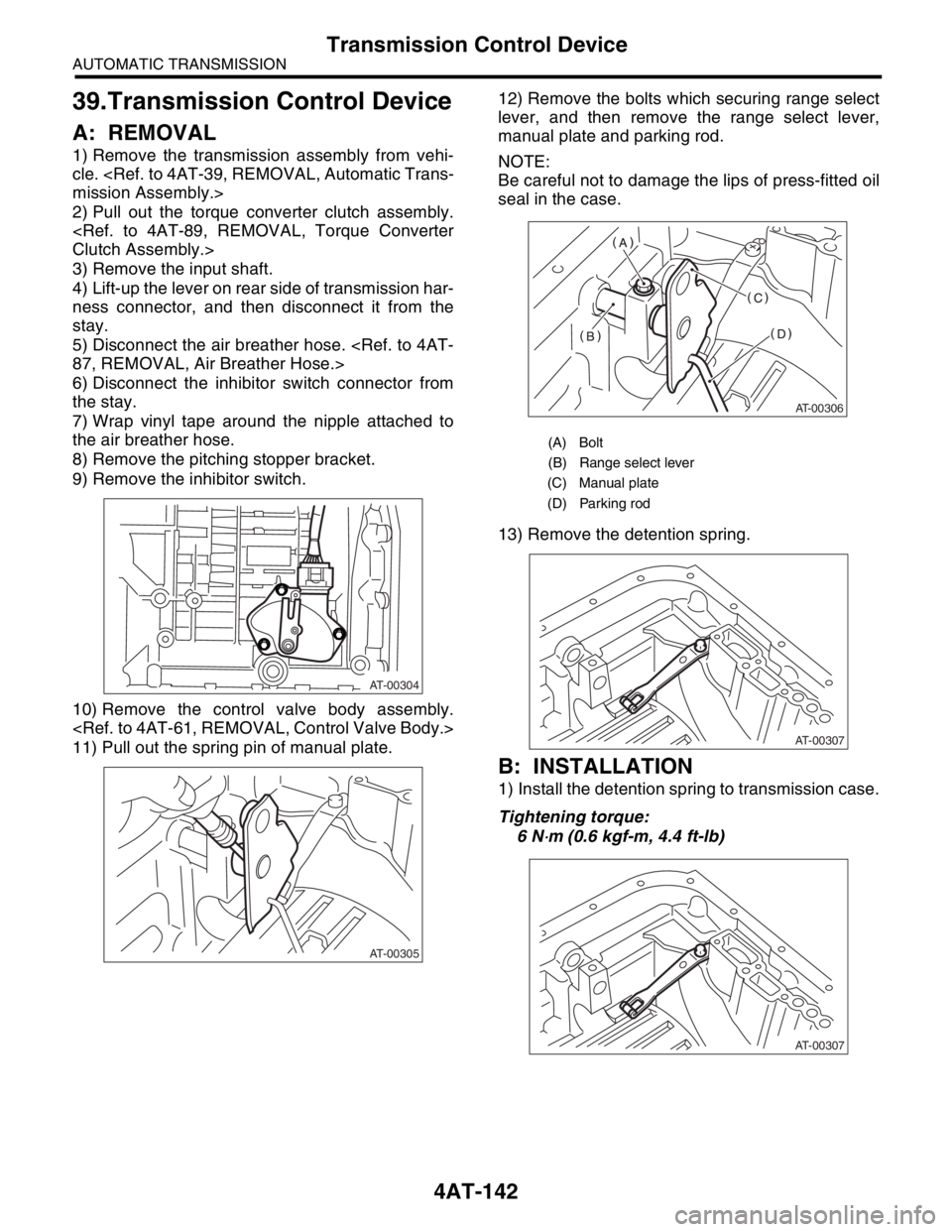
A: REMOVAL
1) Remove the transmission assembly from vehi-
cle.
2) Pull out the torque converter clutch assembly.
3) Remove the input shaft.
4) Lift-up the lever on rear side of transmission har-
ness connector, and then disconnect it from the
stay.
5) Disconnect the air breather hose.
6) Disconnect the inhibitor switch connector from
the stay.
7) Wrap vinyl tape around the nipple attached to
the air breather hose.
8) Remove the pitching stopper bracket.
9) Remove the inhibitor switch.
10) Remove the control valve body assembly.
11) Pull out the spring pin of manual plate.12) Remove the bolts which securing range select
lever, and then remove the range select lever,
manual plate and parking rod.
NOTE:
Be careful not to damage the lips of press-fitted oil
seal in the case.
13) Remove the detention spring.
B: INSTALLATION
1) Install the detention spring to transmission case.
Tightening torque:
6 N
⋅m (0.6 kgf-m, 4.4 ft-lb)
AT-00304
AT-00305
(A) Bolt
(B) Range select lever
(C) Manual plate
(D) Parking rod
AT-00306
AT-00307
AT-00307
Page 2457 of 2870
4AT-143
AUTOMATIC TRANSMISSION
Transmission Control Device
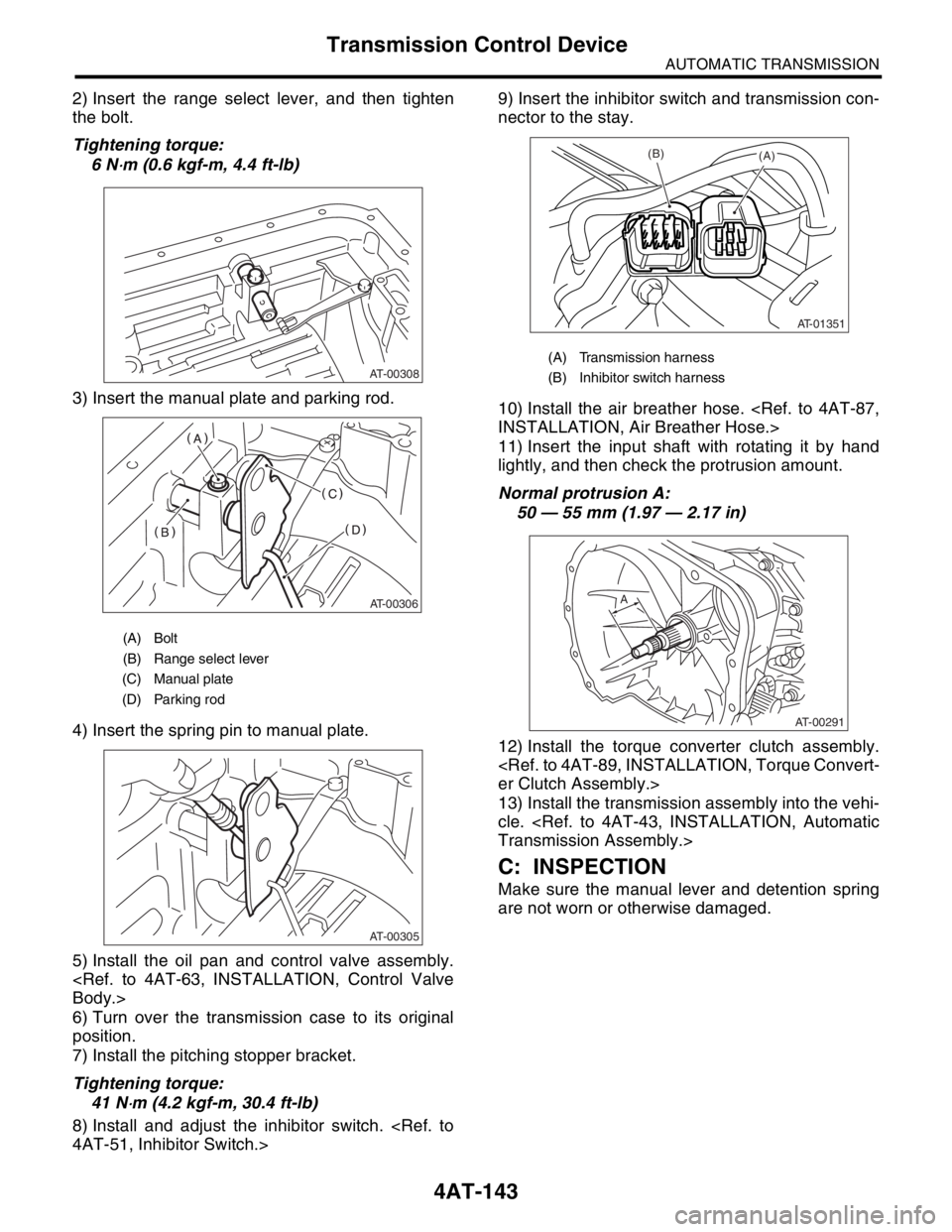
2) Insert the range select lever, and then tighten
the bolt.
Tightening torque:
6 N
⋅m (0.6 kgf-m, 4.4 ft-lb)
3) Insert the manual plate and parking rod.
4) Insert the spring pin to manual plate.
5) Install the oil pan and control valve assembly.
6) Turn over the transmission case to its original
position.
7) Install the pitching stopper bracket.
Tightening torque:
41 N
⋅m (4.2 kgf-m, 30.4 ft-lb)
8) Install and adjust the inhibitor switch.
nector to the stay.
10) Install the air breather hose.
11) Insert the input shaft with rotating it by hand
lightly, and then check the protrusion amount.
Normal protrusion A:
50 — 55 mm (1.97 — 2.17 in)
12) Install the torque converter clutch assembly.
13) Install the transmission assembly into the vehi-
cle.
C: INSPECTION
Make sure the manual lever and detention spring
are not worn or otherwise damaged.
(A) Bolt
(B) Range select lever
(C) Manual plate
(D) Parking rod
AT-00308
AT-00306
AT-00305
(A) Transmission harness
(B) Inhibitor switch harness
AT-01351
(B)(A)
AT-00291
A
Page 2459 of 2870
FUJI HEAVY INDUSTRIES LTD. G8080GE5
2004 FORESTER SERVICE MANUAL QUICK REFERENCE INDEX
TRANSMISSION SECTION
This service manual has been prepared
to provide SUBARU service personnel
with the necessary information and data
for the correct maintenance and repair
of SUBARU vehicles.
This manual includes the procedures
for maintenance, disassembling, reas-
sembling, inspection and adjustment of
components and diagnostics for guid-
ance of experienced mechanics.
Please peruse and utilize this manual
fully to ensure complete repair work for
satisfying our customers by keeping
their vehicle in optimum condition.
When replacement of parts during
repair work is needed, be sure to use
SUBARU genuine parts.
All information, illustration and specifi-
cations contained in this manual are
based on the latest product information
available at the time of publication
approval.CONTROL SYSTEM CS
AUTOMATIC TRANSMISSION 4AT
AUTOMATIC TRANSMISSION
(DIAGNOSTIC)4AT(H4SO)
AUTOMATIC TRANSMISSION
(DIAGNOSTIC)4AT(H4DOTC)
AUTOMATIC TRANSMISSION
(DIAGNOSTIC)4AT(H4DOTC 2.5)
MANUAL TRANSMISSION AND
DIFFERENTIAL5MT
CLUTCH SYSTEM CL
Page 2477 of 2870
![SUBARU FORESTER 2004 Service User Guide 4AT(H4SO)-18
AUTOMATIC TRANSMISSION (DIAGNOSTIC)
Subaru Select Monitor
2. READ CURRENT DATA
1) On the «Main Menu» display screen, select the {Each System Check} and press the [YES] key.
2) On the « SUBARU FORESTER 2004 Service User Guide 4AT(H4SO)-18
AUTOMATIC TRANSMISSION (DIAGNOSTIC)
Subaru Select Monitor
2. READ CURRENT DATA
1) On the «Main Menu» display screen, select the {Each System Check} and press the [YES] key.
2) On the «](/img/17/57426/w960_57426-2476.png)
4AT(H4SO)-18
AUTOMATIC TRANSMISSION (DIAGNOSTIC)
Subaru Select Monitor
2. READ CURRENT DATA
1) On the «Main Menu» display screen, select the {Each System Check} and press the [YES] key.
2) On the «System Selection Menu» display screen, select the {Transmission Control System} and press the
[YES] key.
3) Press the [YES] key after the information of transmission type is displayed.
4) On the «Transmission Diagnosis» display screen, select the {Current Data Display & Save} and press the
[YES] key.
5) On the «Data Display Menu» display screen, select the {Data Display} and press the [YES] key.
6) Using the scroll key, move the display screen up or down until desired data is shown.
A list of the support data is shown in the following table.
NOTE:
For detailed operation procedure, refer to the SUBARU SELECT MONITOR OPERATION MANUAL.
Contents Display Unit of measure
Battery voltage Battery Voltage V
Rear vehicle speed sensor signal Rear Wheel Speed km/h or MPH
Front vehicle speed sensor signal Front Wheel Speed km/h or MPH
Engine speed signal Engine Speed rpm
Automatic transmission fluid temperature signal ATF Temp.°C or °F
Throttle position signal Throttle Sensor Voltage V
Gear position Gear Position —
Line pressure control duty ratio Line Pressure Duty Ratio %
Lock up clutch control duty ratio Lock Up Duty Ratio %
Transfer clutch control duty ratio (AWD model) Transfer Duty Ratio %
Power supply for throttle position sensor Throttle Sensor Power V
Torque converter turbine speed signal Turbine Revolution Speed rpm
2-4 brake timing pressure control duty ratio Brake Clutch Duty Ratio %
Intake manifold pressure sensor voltage Mani. Pressure Voltage V
FWD switch signal FWD Switch ON or OFF
Stop light switch signal Stop Light Switch ON or OFF
Anti lock brake system signal ABS Signal ON or OFF
Cruise control system signal Cruise Control Signal ON or OFF
Parking range signal P Range Signal ON or OFF
Neutral range signal N Range Signal ON or OFF
Reverse range signal R Range Signal ON or OFF
Drive range signal D Range Signal ON or OFF
3rd range signal 3rd Range Signal ON or OFF
2nd range signal 2nd Range Signal ON or OFF
1st range signal 1st Range Signal ON or OFF
Shift control solenoid A Shift Solenoid #1 ON or OFF
Shift control solenoid B Shift Solenoid #2 ON or OFF
Torque control output signal #1 Torque Control Signal 1 ON or OFF
Torque control output signal #2 Torque Control Signal 2 ON or OFF
Torque control cut signal Torque Control Cut Sig. ON or OFF
2-4 brake timing control solenoid valve 2-4 Brake Timing Sol. ON or OFF
Low clutch timing control solenoid valve Low Clutch Timing Sol. ON or OFF
Automatic transmission diagnosis indicator lamp Diagnosis Lamp ON or OFF
Power mode switch signal Power Mode Switch ON or OFF
Hold mode switch signal Hold Mode Switch ON or OFF
Kick down switch signal Kick Down Switch ON or OFF
Automatic transmission fluid temperature lamp ATF Temperature Lamp ON or OFF
Page 2478 of 2870
![SUBARU FORESTER 2004 Service User Guide 4AT(H4SO)-19
AUTOMATIC TRANSMISSION (DIAGNOSTIC)
Subaru Select Monitor
3. CLEAR MEMORY MODE
1) On the «Main Menu» display screen, select the
{2. Each System Check} and press the [YES] key.
2) On the SUBARU FORESTER 2004 Service User Guide 4AT(H4SO)-19
AUTOMATIC TRANSMISSION (DIAGNOSTIC)
Subaru Select Monitor
3. CLEAR MEMORY MODE
1) On the «Main Menu» display screen, select the
{2. Each System Check} and press the [YES] key.
2) On the](/img/17/57426/w960_57426-2477.png)
4AT(H4SO)-19
AUTOMATIC TRANSMISSION (DIAGNOSTIC)
Subaru Select Monitor
3. CLEAR MEMORY MODE
1) On the «Main Menu» display screen, select the
{2. Each System Check} and press the [YES] key.
2) On the «System Selection Menu» display screen,
select the {Transmission Control System} and press
the [YES] key.
3) Press the [YES] key after the information of
transmission type is displayed.
4) On the «Transmission Diagnosis» display screen,
select the {Clear Memory} and press the [YES] key.
5) When the “Done” and “Turn Ignition Switch OFF”
are shown on display screen, turn the Subaru Se-
lect Monitor and ignition switch to OFF.
NOTE:
For detailed operation procedure, refer to the SUB-
ARU SELECT MONITOR OPERATION MANUAL.