timing belt SUBARU FORESTER 2004 Service Owner's Guide
[x] Cancel search | Manufacturer: SUBARU, Model Year: 2004, Model line: FORESTER, Model: SUBARU FORESTER 2004Pages: 2870, PDF Size: 38.67 MB
Page 966 of 2870
ME(H4SO)-95
MECHANICAL
Engine Trouble in General
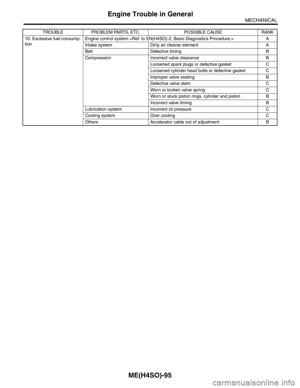
10. Excessive fuel consump-
tionEngine control system
Intake system Dirty air cleaner element A
Belt Defective timing B
Compression Incorrect valve clearance B
Loosened spark plugs or defective gasket C
Loosened cylinder head bolts or defective gasket C
Improper valve seating B
Defective valve stem C
Worn or broken valve spring C
Worn or stuck piston rings, cylinder and piston B
Incorrect valve timing B
Lubrication system Incorrect oil pressure C
Cooling system Over cooling C
Others Accelerator cable out of adjustment B TROUBLE PROBLEM PARTS, ETC. POSSIBLE CAUSE RANK
Page 967 of 2870
ME(H4SO)-96
MECHANICAL
Engine Noise
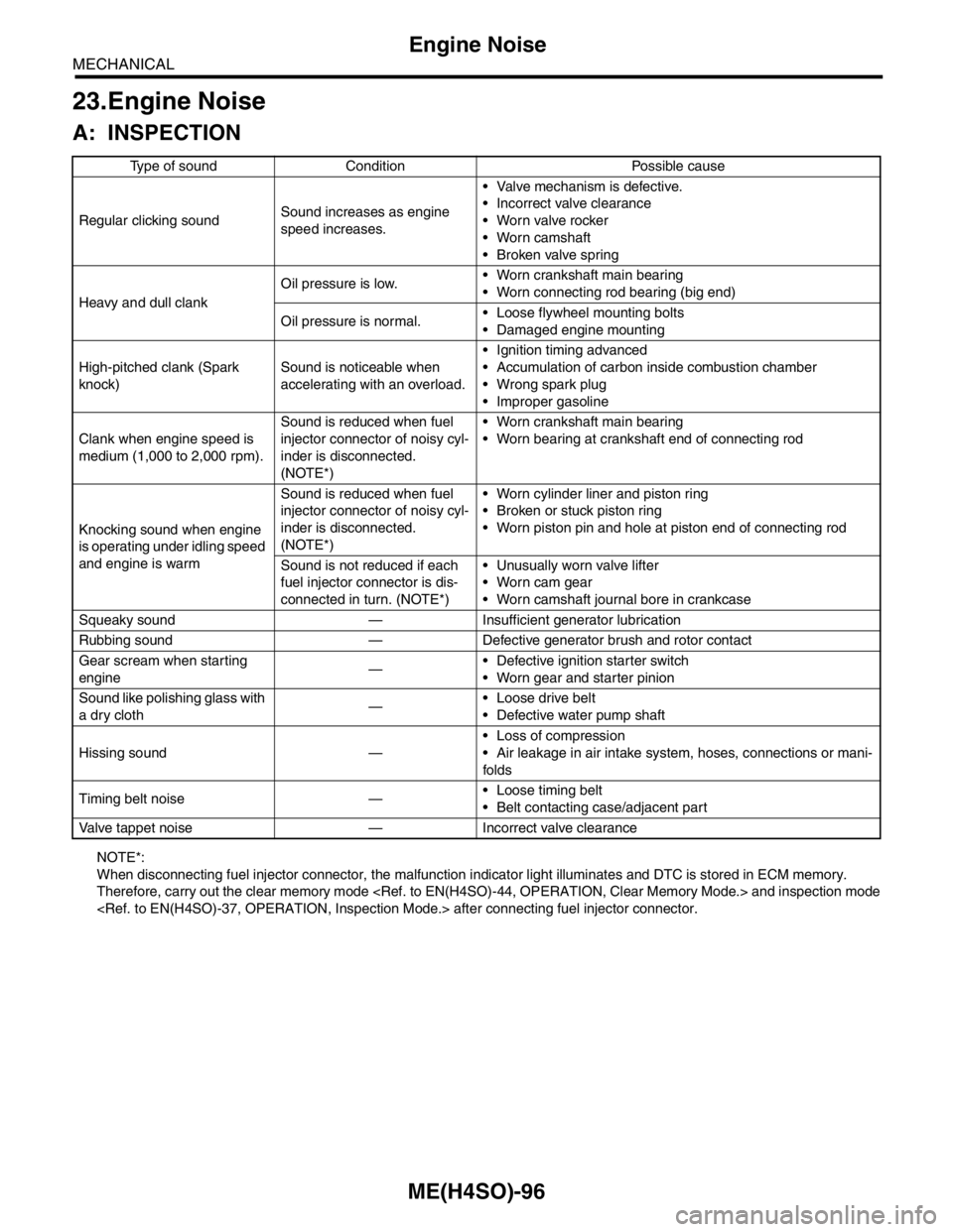
23.Engine Noise
A: INSPECTION
NOTE*:
When disconnecting fuel injector connector, the malfunction indicator light illuminates and DTC is stored in ECM memory.
Therefore, carry out the clear memory mode
Regular clicking soundSound increases as engine
speed increases. Valve mechanism is defective.
Incorrect valve clearance
Worn valve rocker
Worn camshaft
Broken valve spring
Heavy and dull clankOil pressure is low. Worn crankshaft main bearing
Worn connecting rod bearing (big end)
Oil pressure is normal. Loose flywheel mounting bolts
Damaged engine mounting
High-pitched clank (Spark
knock)Sound is noticeable when
accelerating with an overload. Ignition timing advanced
Accumulation of carbon inside combustion chamber
Wrong spark plug
Improper gasoline
Clank when engine speed is
medium (1,000 to 2,000 rpm).Sound is reduced when fuel
injector connector of noisy cyl-
inder is disconnected.
(NOTE*) Worn crankshaft main bearing
Worn bearing at crankshaft end of connecting rod
Knocking sound when engine
is operating under idling speed
and engine is warmSound is reduced when fuel
injector connector of noisy cyl-
inder is disconnected.
(NOTE*) Worn cylinder liner and piston ring
Broken or stuck piston ring
Worn piston pin and hole at piston end of connecting rod
Sound is not reduced if each
fuel injector connector is dis-
connected in turn. (NOTE*) Unusually worn valve lifter
Worn cam gear
Worn camshaft journal bore in crankcase
Squeaky sound — Insufficient generator lubrication
Rubbing sound — Defective generator brush and rotor contact
Gear scream when starting
engine— Defective ignition starter switch
Worn gear and starter pinion
Sound like polishing glass with
a dry cloth— Loose drive belt
Defective water pump shaft
Hissing sound — Loss of compression
Air leakage in air intake system, hoses, connections or mani-
folds
Timing belt noise — Loose timing belt
Belt contacting case/adjacent part
Valve tappet noise — Incorrect valve clearance
Page 1004 of 2870
CO(H4SO)-21
COOLING
Water Pump
4. Water Pump
A: REMOVAL
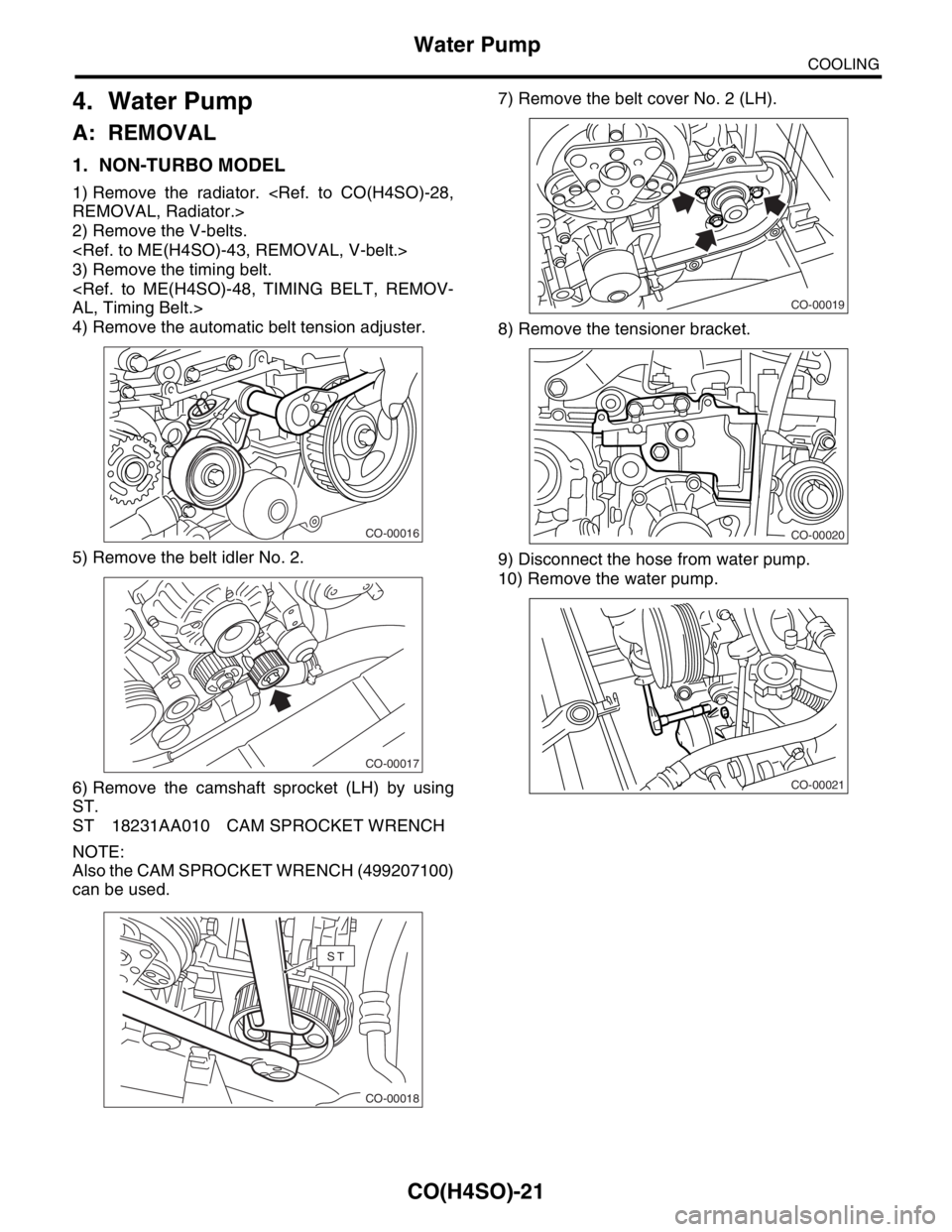
1. NON-TURBO MODEL
1) Remove the radiator.
2) Remove the V-belts.
3) Remove the timing belt.
4) Remove the automatic belt tension adjuster.
5) Remove the belt idler No. 2.
6) Remove the camshaft sprocket (LH) by using
ST.
ST 18231AA010 CAM SPROCKET WRENCH
NOTE:
Also the CAM SPROCKET WRENCH (499207100)
can be used.7) Remove the belt cover No. 2 (LH).
8) Remove the tensioner bracket.
9) Disconnect the hose from water pump.
10) Remove the water pump.
CO-00016
CO-00017
CO-00018
ST
CO-00019
CO-00020
CO-00021
Page 1005 of 2870
CO(H4SO)-22
COOLING
Water Pump
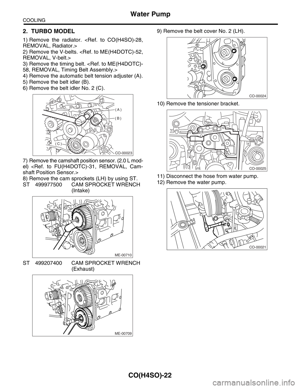
2. TURBO MODEL
1) Remove the radiator.
2) Remove the V-belts.
3) Remove the timing belt.
4) Remove the automatic belt tension adjuster (A).
5) Remove the belt idler (B).
6) Remove the belt idler No. 2 (C).
7) Remove the camshaft position sensor. (2.0 L mod-
el)
8) Remove the cam sprockets (LH) by using ST.
ST 499977500 CAM SPROCKET WRENCH
(Intake)
ST 499207400 CAM SPROCKET WRENCH
(Exhaust)9) Remove the belt cover No. 2 (LH).
10) Remove the tensioner bracket.
11) Disconnect the hose from water pump.
12) Remove the water pump.
CO-00023
(A)
(B)
(C)
ME-00710
ME-00709
CO-00024
CO-00025
CO-00021
Page 1006 of 2870
CO(H4SO)-23
COOLING
Water Pump
B: INSTALLATION
1. NON-TURBO MODEL
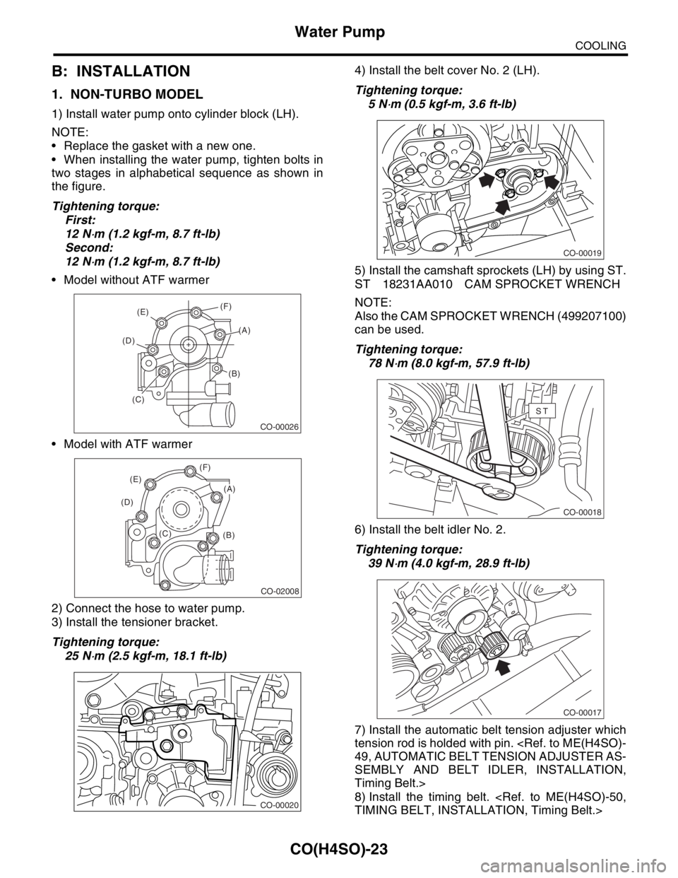
1) Install water pump onto cylinder block (LH).
NOTE:
Replace the gasket with a new one.
When installing the water pump, tighten bolts in
two stages in alphabetical sequence as shown in
the figure.
Tightening torque:
First:
12 N
⋅m (1.2 kgf-m, 8.7 ft-lb)
Second:
12 N
⋅m (1.2 kgf-m, 8.7 ft-lb)
Model without ATF warmer
Model with ATF warmer
2) Connect the hose to water pump.
3) Install the tensioner bracket.
Tightening torque:
25 N
⋅m (2.5 kgf-m, 18.1 ft-lb)4) Install the belt cover No. 2 (LH).
Tightening torque:
5 N
⋅m (0.5 kgf-m, 3.6 ft-lb)
5) Install the camshaft sprockets (LH) by using ST.
ST 18231AA010 CAM SPROCKET WRENCH
NOTE:
Also the CAM SPROCKET WRENCH (499207100)
can be used.
Tightening torque:
78 N
⋅m (8.0 kgf-m, 57.9 ft-lb)
6) Install the belt idler No. 2.
Tightening torque:
39 N
⋅m (4.0 kgf-m, 28.9 ft-lb)
7) Install the automatic belt tension adjuster which
tension rod is holded with pin.
SEMBLY AND BELT IDLER, INSTALLATION,
Timing Belt.>
8) Install the timing belt.
CO-00026
(E)
(D)
(B)
(C)(A) (F)
CO-02008
(B) (C) (D)(E)(F)
(A)
CO-00020
CO-00019
CO-00018
ST
CO-00017
Page 1008 of 2870
CO(H4SO)-25
COOLING
Water Pump
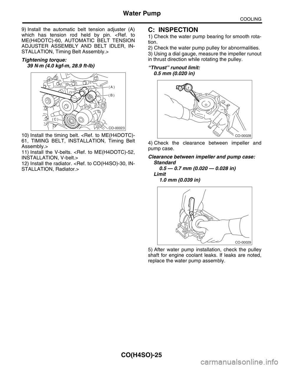
9) Install the automatic belt tension adjuster (A)
which has tension rod held by pin.
ADJUSTER ASSEMBLY AND BELT IDLER, IN-
STALLATION, Timing Belt Assembly.>
Tightening torque:
39 N
⋅m (4.0 kgf-m, 28.9 ft-lb)
10) Install the timing belt.
Assembly.>
11) Install the V-belts.
12) Install the radiator.
C: INSPECTION
1) Check the water pump bearing for smooth rota-
tion.
2) Check the water pump pulley for abnormalities.
3) Using a dial gauge, measure the impeller runout
in thrust direction while rotating the pulley.
“Thrust” runout limit:
0.5 mm (0.020 in)
4) Check the clearance between impeller and
pump case.
Clearance between impeller and pump case:
Standard
0.5 — 0.7 mm (0.020 — 0.028 in)
Limit
1.0 mm (0.039 in)
5) After water pump installation, check the pulley
shaft for engine coolant leaks. If leaks are noted,
replace the water pump assembly.
CO-00023
(A)
(B)
(C)
CO-00028
CO-00029
Page 1026 of 2870
CO(H4SO)-43
COOLING
Engine Cooling System Trouble in General
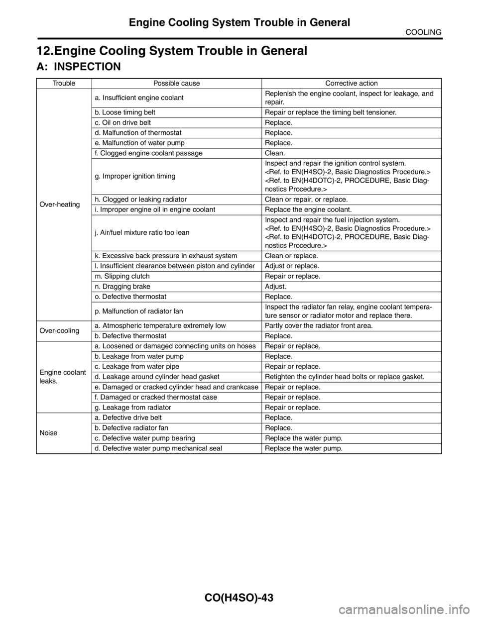
12.Engine Cooling System Trouble in General
A: INSPECTION
Trouble Possible cause Corrective action
Over-heatinga. Insufficient engine coolantReplenish the engine coolant, inspect for leakage, and
repair.
b. Loose timing belt Repair or replace the timing belt tensioner.
c. Oil on drive belt Replace.
d. Malfunction of thermostat Replace.
e. Malfunction of water pump Replace.
f. Clogged engine coolant passage Clean.
g. Improper ignition timingInspect and repair the ignition control system.
h. Clogged or leaking radiator Clean or repair, or replace.
i. Improper engine oil in engine coolant Replace the engine coolant.
j. Air/fuel mixture ratio too leanInspect and repair the fuel injection system.
k. Excessive back pressure in exhaust system Clean or replace.
l. Insufficient clearance between piston and cylinder Adjust or replace.
m. Slipping clutch Repair or replace.
n. Dragging brake Adjust.
o. Defective thermostat Replace.
p. Malfunction of radiator fanInspect the radiator fan relay, engine coolant tempera-
ture sensor or radiator motor and replace there.
Over-coolinga. Atmospheric temperature extremely low Partly cover the radiator front area.
b. Defective thermostat Replace.
Engine coolant
leaks.a. Loosened or damaged connecting units on hoses Repair or replace.
b. Leakage from water pump Replace.
c. Leakage from water pipe Repair or replace.
d. Leakage around cylinder head gasket Retighten the cylinder head bolts or replace gasket.
e. Damaged or cracked cylinder head and crankcase Repair or replace.
f. Damaged or cracked thermostat case Repair or replace.
g. Leakage from radiator Repair or replace.
Noisea. Defective drive belt Replace.
b. Defective radiator fan Replace.
c. Defective water pump bearing Replace the water pump.
d. Defective water pump mechanical seal Replace the water pump.
Page 1041 of 2870
LU(H4SO)-13
LUBRICATION
Oil Pump
12) Remove the timing belt guide. (MT model)
13) Remove the crank sprocket.
14) Remove the bolts which install oil pump onto
cylinder block.
15) Remove the oil pump by using flat tip screw-
driver.
CAUTION:
Be careful not to scratch the mating surfaces of
cylinder block and oil pump.B: INSTALLATION
Install in the reverse order of removal.
Do the following:
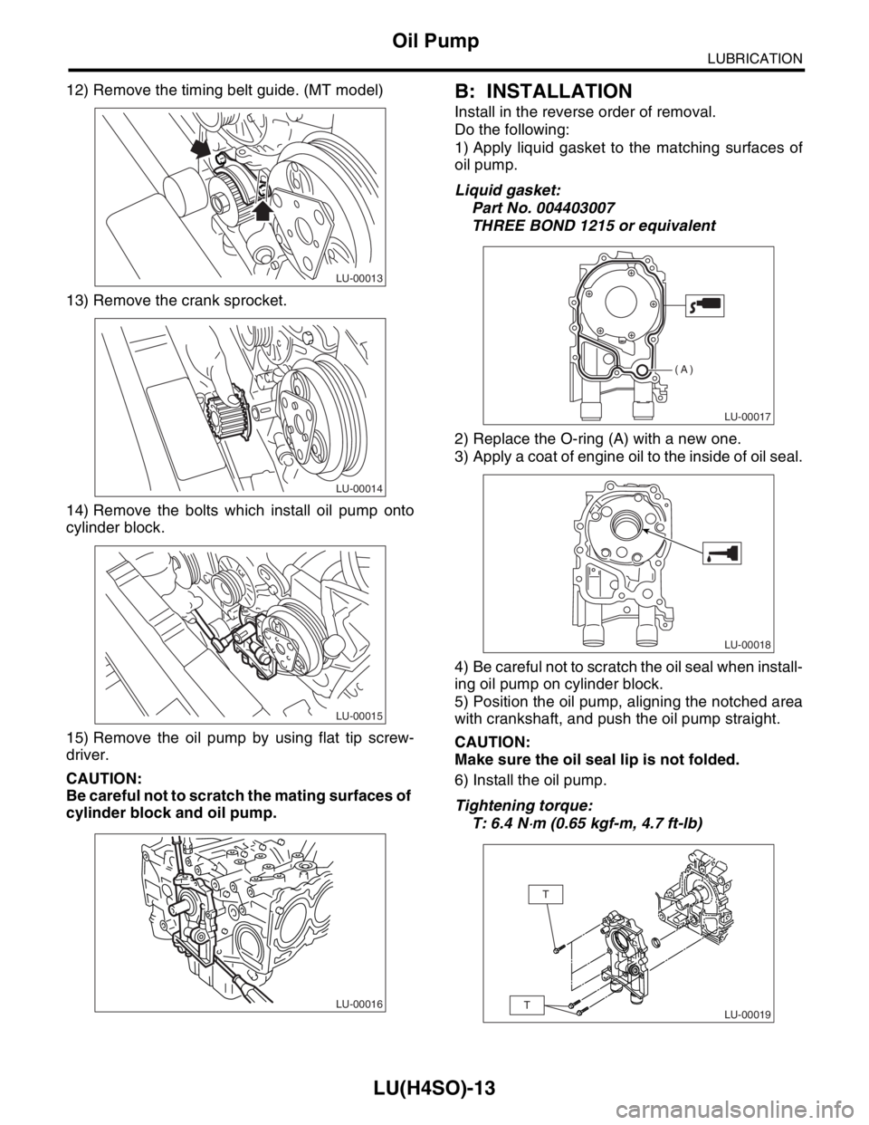
1) Apply liquid gasket to the matching surfaces of
oil pump.
Liquid gasket:
Part No. 004403007
THREE BOND 1215 or equivalent
2) Replace the O-ring (A) with a new one.
3) Apply a coat of engine oil to the inside of oil seal.
4) Be careful not to scratch the oil seal when install-
ing oil pump on cylinder block.
5) Position the oil pump, aligning the notched area
with crankshaft, and push the oil pump straight.
CAUTION:
Make sure the oil seal lip is not folded.
6) Install the oil pump.
Tightening torque:
T: 6.4 N
⋅m (0.65 kgf-m, 4.7 ft-lb)
LU-00013
LU-00014
LU-00015
LU-00016
LU-00017
(A)
LU-00018
LU-00019
T
T
Page 1242 of 2870
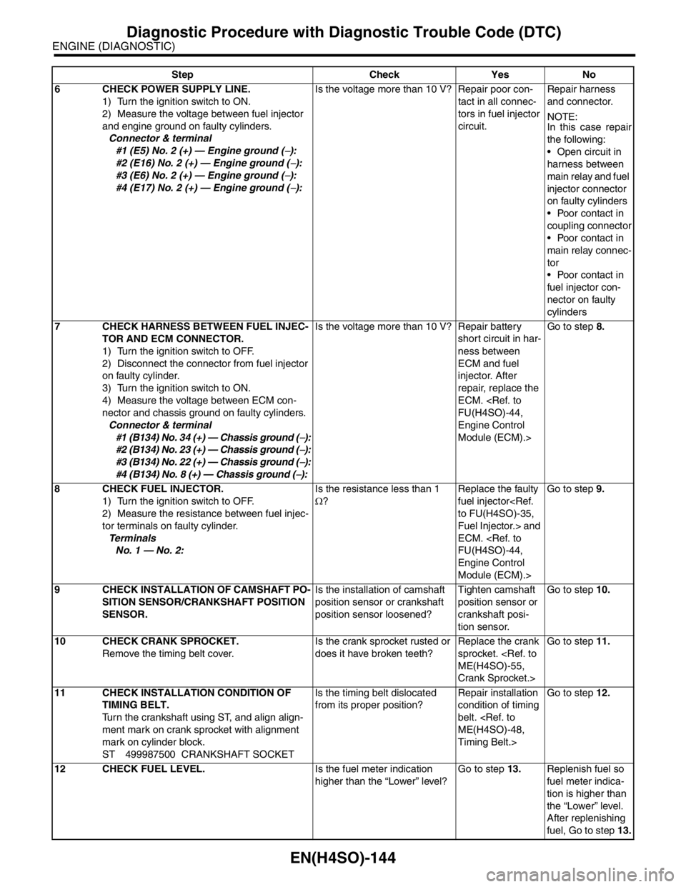
EN(H4SO)-144
ENGINE (DIAGNOSTIC)
Diagnostic Procedure with Diagnostic Trouble Code (DTC)
6 CHECK POWER SUPPLY LINE.
1) Turn the ignition switch to ON.
2) Measure the voltage between fuel injector
and engine ground on faulty cylinders.
Connector & terminal
#1 (E5) No. 2 (+) — Engine ground (
−):
#2 (E16) No. 2 (+) — Engine ground (
−):
#3 (E6) No. 2 (+) — Engine ground (
−):
#4 (E17) No. 2 (+) — Engine ground (
−):Is the voltage more than 10 V? Repair poor con-
tact in all connec-
tors in fuel injector
circuit.Repair harness
and connector.
N
OTE:
In this case repair
the following:
Open circuit in
harness between
main relay and fuel
injector connector
on faulty cylinders
Poor contact in
coupling connector
Poor contact in
main relay connec-
tor
Poor contact in
fuel injector con-
nector on faulty
cylinders
7 CHECK HARNESS BETWEEN FUEL INJEC-
TOR AND ECM CONNECTOR.
1) Turn the ignition switch to OFF.
2) Disconnect the connector from fuel injector
on faulty cylinder.
3) Turn the ignition switch to ON.
4) Measure the voltage between ECM con-
nector and chassis ground on faulty cylinders.
Connector & terminal
#1 (B134) No. 34 (+) — Chassis ground (
−):
#2 (B134) No. 23 (+) — Chassis ground (
−):
#3 (B134) No. 22 (+) — Chassis ground (
−):
#4 (B134) No. 8 (+) — Chassis ground (
−):Is the voltage more than 10 V? Repair battery
short circuit in har-
ness between
ECM and fuel
injector. After
repair, replace the
ECM.
Engine Control
Module (ECM).>Go to step 8.
8 CHECK FUEL INJECTOR.
1) Turn the ignition switch to OFF.
2) Measure the resistance between fuel injec-
tor terminals on faulty cylinder.
Te r m i n a l s
No. 1 — No. 2:Is the resistance less than 1
Ω?Replace the faulty
fuel injector
Fuel Injector.> and
ECM.
Engine Control
Module (ECM).>Go to step 9.
9 CHECK INSTALLATION OF CAMSHAFT PO-
SITION SENSOR/CRANKSHAFT POSITION
SENSOR.Is the installation of camshaft
position sensor or crankshaft
position sensor loosened?Tighten camshaft
position sensor or
crankshaft posi-
tion sensor.Go to step 10.
10 CHECK CRANK SPROCKET.
Remove the timing belt cover.Is the crank sprocket rusted or
does it have broken teeth?Replace the crank
sprocket.
Crank Sprocket.>Go to step 11.
11 CHECK INSTALLATION CONDITION OF
TIMING BELT.
Turn the crankshaft using ST, and align align-
ment mark on crank sprocket with alignment
mark on cylinder block.
ST 499987500 CRANKSHAFT SOCKETIs the timing belt dislocated
from its proper position?Repair installation
condition of timing
belt.
Timing Belt.>Go to step 12.
12 CHECK FUEL LEVEL.Is the fuel meter indication
higher than the “Lower” level?Go to step 13.Replenish fuel so
fuel meter indica-
tion is higher than
the “Lower” level.
After replenishing
fuel, Go to step 13. Step Check Yes No
Page 1245 of 2870

EN(H4SO)-147
ENGINE (DIAGNOSTIC)
Diagnostic Procedure with Diagnostic Trouble Code (DTC)
23 GROUP OF #3 AND #4 CYLINDERS.Are there faults in #3 and #4
cylinders?Repair or replace
the faulty par t.
N
OTE:
Check the fol-
lowing items:
Spark plug
Fuel injector
Ignition coil
If no abnormal is
discovered, check
for “16. D: IGNI-
TION CONTROL
SYSTEM” of #3
and #4 cylinders
side.
IGNITION CON-
TROL SYSTEM,
Diagnostics for
Engine Starting
Fa il u r e. >Go to DTC P0171.
DTC P0171 SYS-
TEM TOO LEAN
(BANK 1), Diag-
nostic Procedure
with Diagnostic
Trouble Code
(DTC).>
24 GROUP OF #1 AND #3 CYLINDERS.Are there faults in #1 and #3
cylinders?Repair or replace
the faulty par t.
N
OTE:
Check the follow-
ing items:
Spark plug
Fuel injector
Skipping timing
belt teethGo to DTC P0171.
DTC P0171 SYS-
TEM TOO LEAN
(BANK 1), Diag-
nostic Procedure
with Diagnostic
Trouble Code
(DTC).>
25 GROUP OF #2 AND #4 CYLINDERS.Are there faults in #2 and #4
cylinders?Repair or replace
the faulty par t.
NOTE:
Check the follow-
ing items:
Spark plug
Fuel injector
Compression
ratio
Skipping timing
belt teethGo to DTC P0171.
DTC P0171 SYS-
TEM TOO LEAN
(BANK 1), Diag-
nostic Procedure
with Diagnostic
Trouble Code
(DTC).>
26 CYLINDER AT RANDOM.Is the engine idle rough? Go to DTC P0171.
DTC P0171 SYS-
TEM TOO LEAN
(BANK 1), Diag-
nostic Procedure
with Diagnostic
Trouble Code
(DTC).>Repair or replace
the faulty part.
N
OTE:
Check the follow-
ing items:
Spark plug
Fuel injector
Compression
ratio Step Check Yes No