brake SUBARU FORESTER 2004 Service Service Manual
[x] Cancel search | Manufacturer: SUBARU, Model Year: 2004, Model line: FORESTER, Model: SUBARU FORESTER 2004Pages: 2870, PDF Size: 38.67 MB
Page 741 of 2870
PM-4
PERIODIC MAINTENANCE SERVICE
Schedule
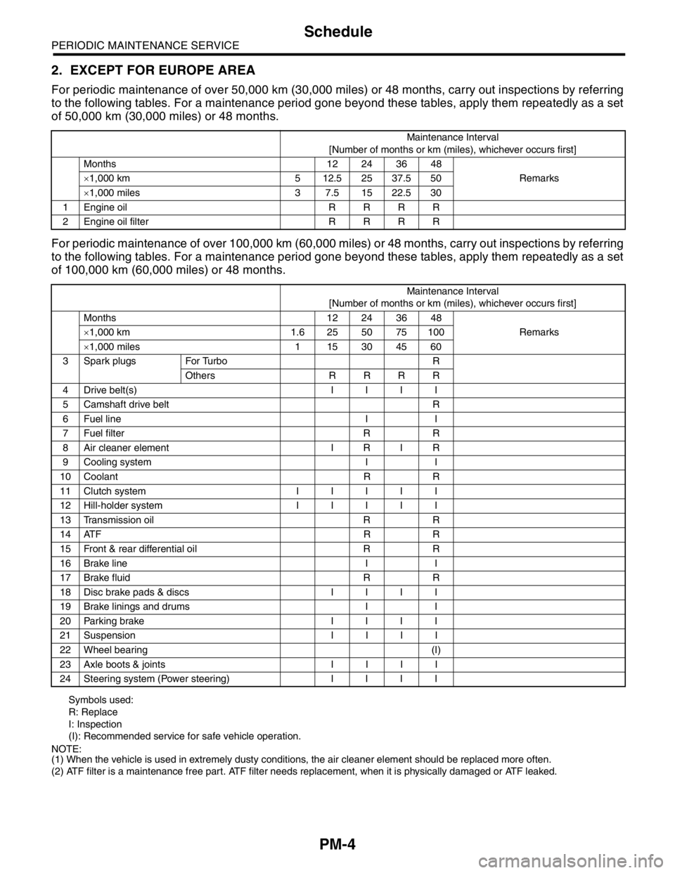
2. EXCEPT FOR EUROPE AREA
For periodic maintenance of over 50,000 km (30,000 miles) or 48 months, carry out inspections by referring
to the following tables. For a maintenance period gone beyond these tables, apply them repeatedly as a set
of 50,000 km (30,000 miles) or 48 months.
For periodic maintenance of over 100,000 km (60,000 miles) or 48 months, carry out inspections by referring
to the following tables. For a maintenance period gone beyond these tables, apply them repeatedly as a set
of 100,000 km (60,000 miles) or 48 months.
Symbols used:
R: Replace
I: Inspection
(I): Recommended service for safe vehicle operation.
N
OTE:
(1) When the vehicle is used in extremely dusty conditions, the air cleaner element should be replaced more often.
(2) ATF filter is a maintenance free part. ATF filter needs replacement, when it is physically damaged or ATF leaked.Maintenance Interval
[Number of months or km (miles), whichever occurs first]
Months 12 24 36 48
Remarks ×1,000 km 5 12.5 25 37.5 50
×1,000 miles 3 7.5 15 22.5 30
1 Engine oil R R R R
2 Engine oil filter R R R R
Maintenance Interval
[Number of months or km (miles), whichever occurs first]
Months 12 24 36 48
Remarks ×1,000 km 1.6 25 50 75 100
×1,000 miles 1 15 30 45 60
3 Spark plugs For Turbo R
Others R R R R
4Drive belt(s) IIII
5 Camshaft drive belt R
6 Fuel line I I
7 Fuel filter R R
8 Air cleaner element I R I R
9 Cooling system I I
10 Coolant R R
11 Clutch system I I I I I
12 Hill-holder system I I I I I
13 Transmission oil R R
14 ATF R R
15 Front & rear differential oil R R
16 Brake line I I
17 Brake fluid R R
18 Disc brake pads & discs I I I I
19 Brake linings and drums I I
20 Parking brake I I I I
21 Suspension I I I I
22 Wheel bearing (I)
23 Axle boots & joints I I I I
24 Steering system (Power steering) I I I I
Page 742 of 2870
PM-5
PERIODIC MAINTENANCE SERVICE
Schedule
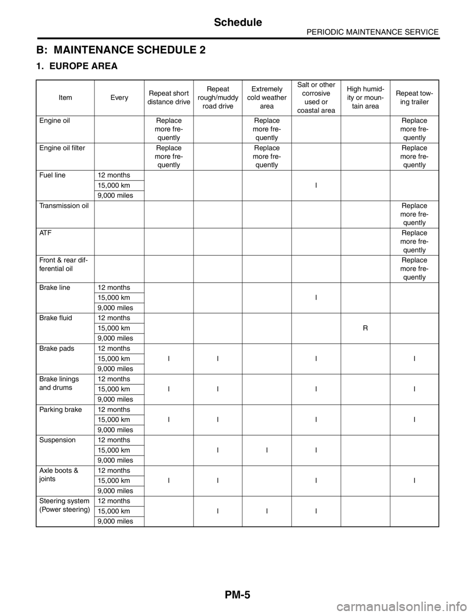
B: MAINTENANCE SCHEDULE 2
1. EUROPE AREA
Item EveryRepeat short
distance driveRepeat
rough/muddy
road driveExtremely
cold weather
areaSalt or other
corrosive
used or
coastal areaHigh humid-
ity or moun-
tain areaRepeat tow-
ing trailer
Engine oil Replace
more fre-
quentlyReplace
more fre-
quentlyReplace
more fre-
quently
Engine oil filter Replace
more fre-
quentlyReplace
more fre-
quentlyReplace
more fre-
quently
Fuel line 12 months
I 15,000 km
9,000 miles
Transmission oilReplace
more fre-
quently
AT FReplace
more fre-
quently
Front & rear dif-
ferential oilReplace
more fre-
quently
Brake line 12 months
I 15,000 km
9,000 miles
Brake fluid 12 months
R 15,000 km
9,000 miles
Brake pads 12 months
II I I 15,000 km
9,000 miles
Brake linings
and drums12 months
II I I 15,000 km
9,000 miles
Parking brake 12 months
II I I 15,000 km
9,000 miles
Suspension 12 months
III 15,000 km
9,000 miles
Axle boots &
joints12 months
II I I 15,000 km
9,000 miles
Steering system
(Power steering)12 months
III 15,000 km
9,000 miles
Page 743 of 2870

PM-6
PERIODIC MAINTENANCE SERVICE
Schedule
2. EXCEPT FOR EUROPE AREA
Item EveryRepeat short
distance driveRepeat
rough/muddy
road driveExtremely
cold weather
areaSalt or other
corrosive
used or
coastal areaHigh humid-
ity or moun-
tain areaRepeat tow-
ing trailer
Engine oil Replace
more fre-
quentlyReplace
more fre-
quentlyReplace
more fre-
quently
Engine oil filter Replace
more fre-
quentlyReplace
more fre-
quentlyReplace
more fre-
quently
Fuel line 6 months
I 12,500 km
7,500 miles
Transmission oilReplace
more fre-
quently
AT FReplace
more fre-
quently
Front & rear dif-
ferential oilReplace
more fre-
quently
Brake line 6 months
I 12,500 km
7,500 miles
Brake fluid 12 months
R 25,000 km
15,000 miles
Brake pads 6 months
II I I 12,500 km
7,500 miles
Brake linings
and drums6 months
II I I 12,500 km
7,500 miles
Parking brake 6 months
II I I 12,500 km
7,500 miles
Suspension 6 months
III 12,500 km
7,500 miles
Axle boots &
joints6 months
II I I 12,500 km
7,500 miles
Steering system
(Power steering)6 months
III 12,500 km
7,500 miles
Page 760 of 2870
PM-23
PERIODIC MAINTENANCE SERVICE
Clutch System
13.Clutch System
A: INSPECTION AND ADJUSTMENT
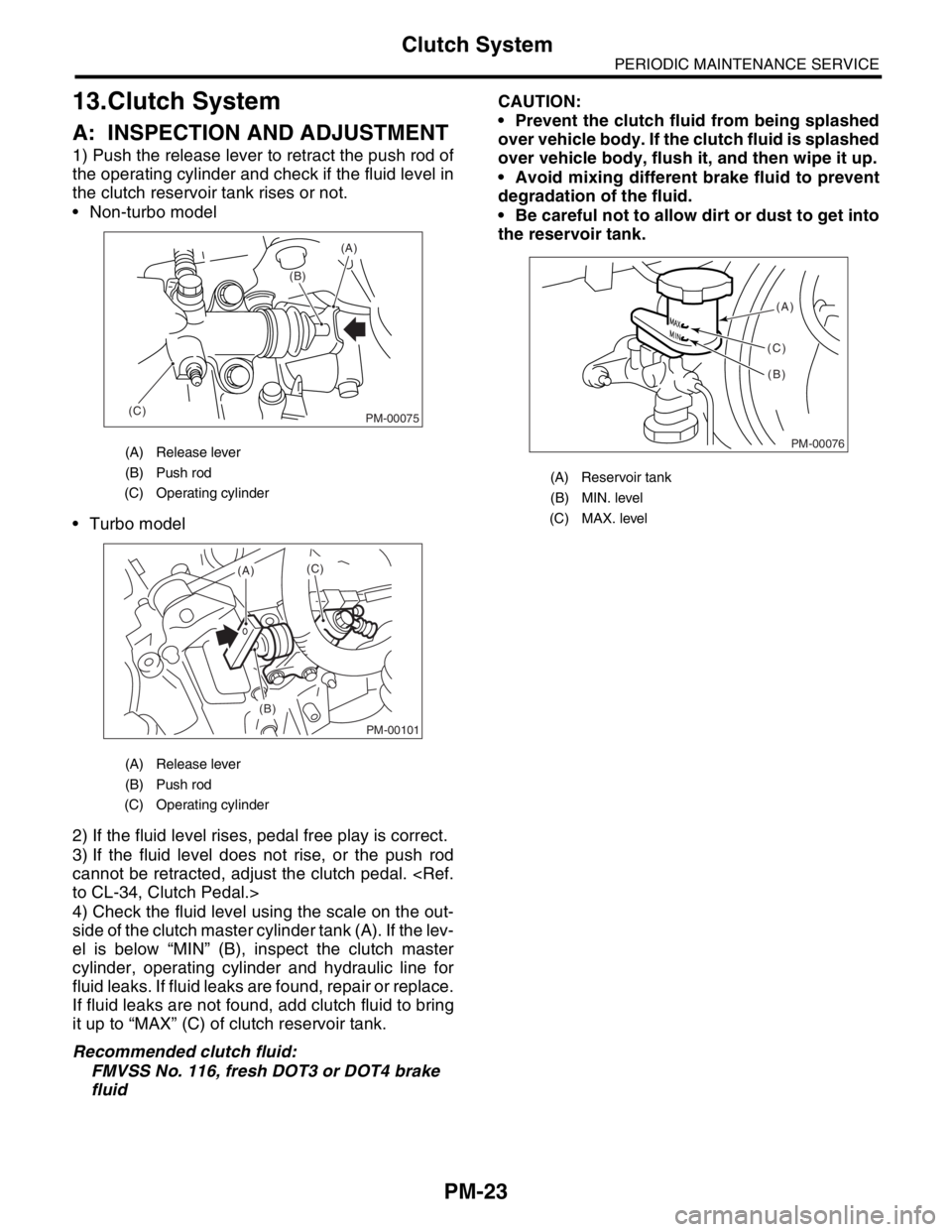
1) Push the release lever to retract the push rod of
the operating cylinder and check if the fluid level in
the clutch reservoir tank rises or not.
Non-turbo model
Turbo model
2) If the fluid level rises, pedal free play is correct.
3) If the fluid level does not rise, or the push rod
cannot be retracted, adjust the clutch pedal.
4) Check the fluid level using the scale on the out-
side of the clutch master cylinder tank (A). If the lev-
el is below “MIN” (B), inspect the clutch master
cylinder, operating cylinder and hydraulic line for
fluid leaks. If fluid leaks are found, repair or replace.
If fluid leaks are not found, add clutch fluid to bring
it up to “MAX” (C) of clutch reservoir tank.
Recommended clutch fluid:
FMVSS No. 116, fresh DOT3 or DOT4 brake
fluidCAUTION:
Prevent the clutch fluid from being splashed
over vehicle body. If the clutch fluid is splashed
over vehicle body, flush it, and then wipe it up.
Avoid mixing different brake fluid to prevent
degradation of the fluid.
Be careful not to allow dirt or dust to get into
the reservoir tank.
(A) Release lever
(B) Push rod
(C) Operating cylinder
(A) Release lever
(B) Push rod
(C) Operating cylinder
PM-00075
(A)
(C)(B)
PM-00101
(A)
(B)(C)
(A) Reservoir tank
(B) MIN. level
(C) MAX. level
PM-00076
(A)
(B) (C)
Page 767 of 2870
PM-30
PERIODIC MAINTENANCE SERVICE
Brake Line
18.Brake Line
A: INSPECTION
1. BRAKE LINE
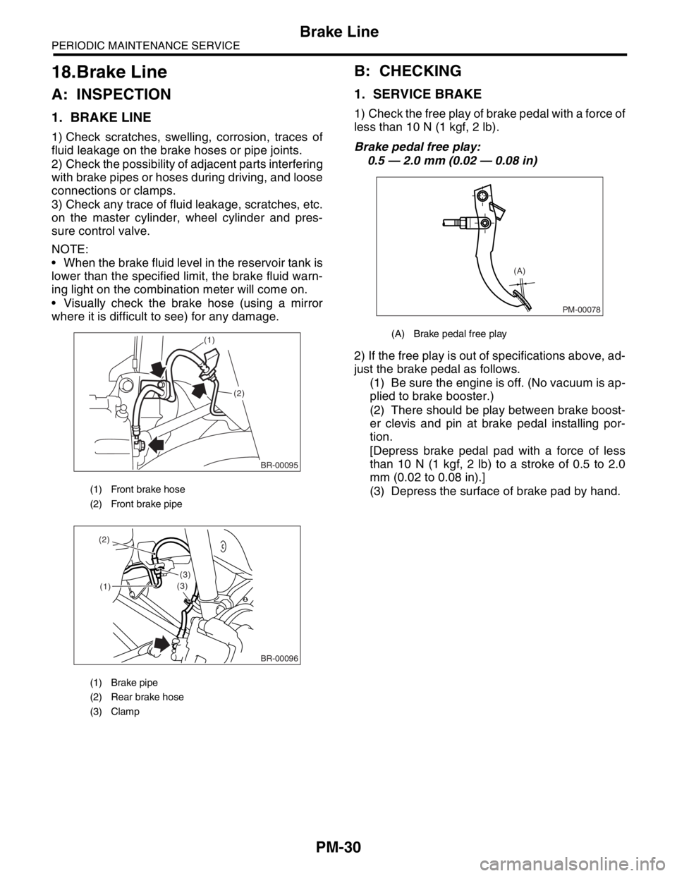
1) Check scratches, swelling, corrosion, traces of
fluid leakage on the brake hoses or pipe joints.
2) Check the possibility of adjacent parts interfering
with brake pipes or hoses during driving, and loose
connections or clamps.
3) Check any trace of fluid leakage, scratches, etc.
on the master cylinder, wheel cylinder and pres-
sure control valve.
NOTE:
When the brake fluid level in the reservoir tank is
lower than the specified limit, the brake fluid warn-
ing light on the combination meter will come on.
Visually check the brake hose (using a mirror
where it is difficult to see) for any damage.
B: CHECKING
1. SERVICE BRAKE
1) Check the free play of brake pedal with a force of
less than 10 N (1 kgf, 2 lb).
Brake pedal free play:
0.5 — 2.0 mm (0.02 — 0.08 in)
2) If the free play is out of specifications above, ad-
just the brake pedal as follows.
(1) Be sure the engine is off. (No vacuum is ap-
plied to brake booster.)
(2) There should be play between brake boost-
er clevis and pin at brake pedal installing por-
tion.
[Depress brake pedal pad with a force of less
than 10 N (1 kgf, 2 lb) to a stroke of 0.5 to 2.0
mm (0.02 to 0.08 in).]
(3) Depress the surface of brake pad by hand.
(1) Front brake hose
(2) Front brake pipe
(1) Brake pipe
(2) Rear brake hose
(3) Clamp
BR-00095
(1)
(2)
(1)
(3)
(3) (2)
BR-00096
(A) Brake pedal free play
PM-00078
(A)
Page 768 of 2870
PM-31
PERIODIC MAINTENANCE SERVICE
Brake Line
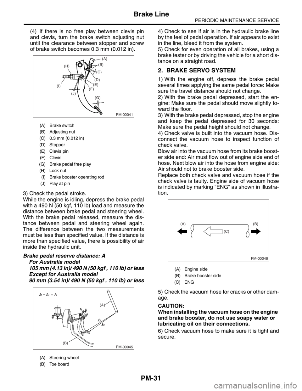
(4) If there is no free play between clevis pin
and clevis, turn the brake switch adjusting nut
until the clearance between stopper and screw
of brake switch becomes 0.3 mm (0.012 in).
3) Check the pedal stroke.
While the engine is idling, depress the brake pedal
with a 490 N (50 kgf, 110 lb) load and measure the
distance between brake pedal and steering wheel.
With the brake pedal released, measure the dis-
tance between pedal and steering wheel again.
The difference between the two measurements
must be less than specified value. If the distance is
more than specified value, there is possibility of air
inside the hydraulic unit.
Brake pedal reserve distance: A
For Australia model
105 mm (4.13 in)/ 490 N (50 kgf , 110 lb) or less
Except for Australia model
90 mm (3.54 in)/ 490 N (50 kgf , 110 lb) or less4) Check to see if air is in the hydraulic brake line
by the feel of pedal operation. If air appears to exist
in the line, bleed it from the system.
5) Check for even operation of all brakes, using a
brake tester or by driving the vehicle for a short dis-
tance on a straight road.
2. BRAKE SERVO SYSTEM
1) With the engine off, depress the brake pedal
several times applying the same pedal force: Make
sure the travel distance should not change.
2) With the brake pedal depressed, start the en-
gine: Make sure the pedal should move slightly to-
ward the floor.
3) With the brake pedal depressed, stop the engine
and keep the pedal depressed for 30 seconds:
Make sure the pedal height should not change.
4) Check valve is built into the vacuum hose. Dis-
connect the vacuum hose to inspect function of
check valve.
Blow air into the vacuum hose from its brake boost-
er side end: Air must flow out of engine side end of
hose. Next blow air into the hose from engine side:
Air should not to brake booster side.
Replace both check valve and vacuum hose if the
check valve is faulty. Engine side of vacuum hose
is indicated by marking “ENG” as shown in illustra-
tion.
5) Check the vacuum hose for cracks or other dam-
age.
CAUTION:
When installing the vacuum hose on the engine
and brake booster, do not use soapy water or
lubricating oil on their connections.
6) Check vacuum hose to make sure it is tight and
secure.
(A) Brake switch
(B) Adjusting nut
(C) 0.3 mm (0.012 in)
(D) Stopper
(E) Clevis pin
(F) Clevis
(G) Brake pedal free play
(H) Lock nut
(I) Brake booster operating rod
(J) Play at pin
(A) Steering wheel
(B) Toe board
PM-00041
(B)
(G) (H)
(I)
(J)(C)
(D)
(E)
(F)(A)
PM-00045(B)(A) = A
1
12
2
(A) Engine side
(B) Brake booster side
(C) ENG
PM-00046
(B)
(C) (A)
Page 769 of 2870
PM-32
PERIODIC MAINTENANCE SERVICE
Brake Fluid
19.Brake Fluid
A: REPLACEMENT
1) Lift-up the vehicle.
2) Remove both front and rear wheels.
3) Draw out the brake fluid from master cylinder
with syringe.
4) Refill the reservoir tank with recommended
brake fluid.
Recommended brake fluid:
FMVSS No. 116, fresh DOT3 or DOT4 brake
fluid
CAUTION:
Avoid mixing different brands of brake fluid
to prevent degrading the quality of the fluid.
Be careful not to allow dirt or dust to get into
the reservoir tank.
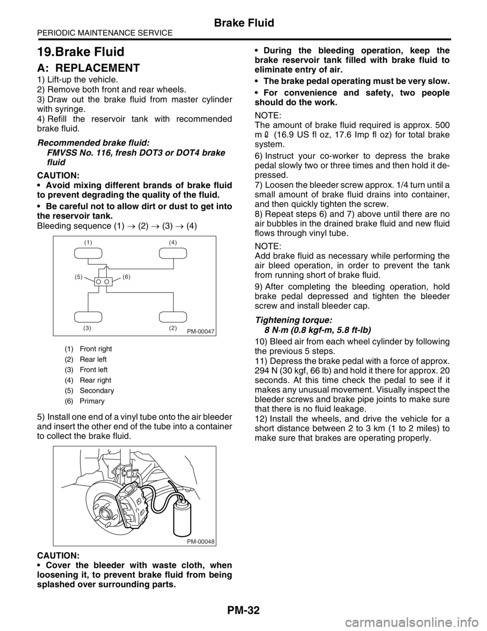
Bleeding sequence (1) → (2) → (3) → (4)
5) Install one end of a vinyl tube onto the air bleeder
and insert the other end of the tube into a container
to collect the brake fluid.
CAUTION:
Cover the bleeder with waste cloth, when
loosening it, to prevent brake fluid from being
splashed over surrounding parts. During the bleeding operation, keep the
brake reservoir tank filled with brake fluid to
eliminate entry of air.
The brake pedal operating must be very slow.
For convenience and safety, two people
should do the work.
NOTE:
The amount of brake fluid required is approx. 500
m2 (16.9 US fl oz, 17.6 Imp fl oz) for total brake
system.
6) Instruct your co-worker to depress the brake
pedal slowly two or three times and then hold it de-
pressed.
7) Loosen the bleeder screw approx. 1/4 turn until a
small amount of brake fluid drains into container,
and then quickly tighten the screw.
8) Repeat steps 6) and 7) above until there are no
air bubbles in the drained brake fluid and new fluid
flows through vinyl tube.
NOTE:
Add brake fluid as necessary while performing the
air bleed operation, in order to prevent the tank
from running short of brake fluid.
9) After completing the bleeding operation, hold
brake pedal depressed and tighten the bleeder
screw and install bleeder cap.
Tightening torque:
8 N·m (0.8 kgf-m, 5.8 ft-lb)
10) Bleed air from each wheel cylinder by following
the previous 5 steps.
11) Depress the brake pedal with a force of approx.
294 N (30 kgf, 66 lb) and hold it there for approx. 20
seconds. At this time check the pedal to see if it
makes any unusual movement. Visually inspect the
bleeder screws and brake pipe joints to make sure
that there is no fluid leakage.
12) Install the wheels, and drive the vehicle for a
short distance between 2 to 3 km (1 to 2 miles) to
make sure that brakes are operating properly.
(1) Front right
(2) Rear left
(3) Front left
(4) Rear right
(5) Secondary
(6) Primary
(1) (4)
(2) (3) (5) (6)
PM-00047
PM-00048
Page 770 of 2870
PM-33
PERIODIC MAINTENANCE SERVICE
Disc Brake Pads and Discs
20.Disc Brake Pads and Discs
A: INSPECTION
1. DISC BRAKE PAD AND DISC
1) Lift-up the vehicle. Then remove the wheels.
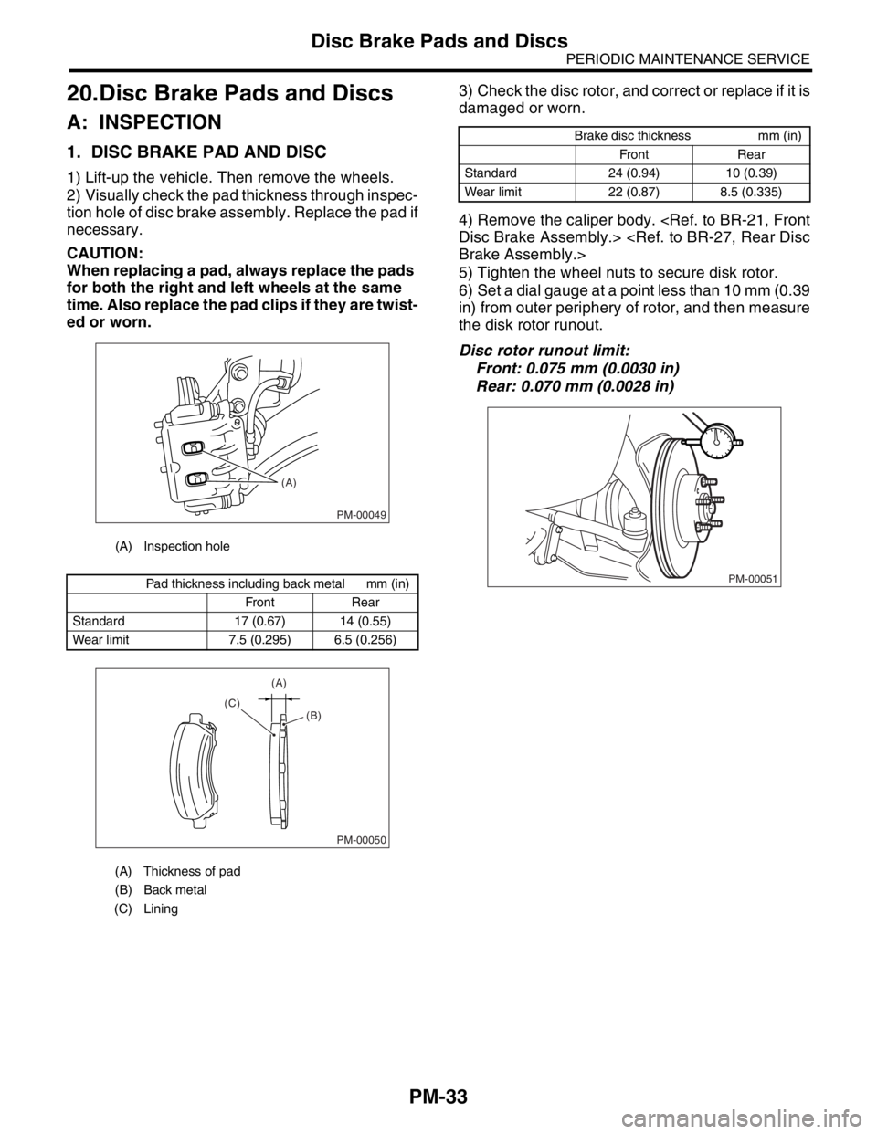
2) Visually check the pad thickness through inspec-
tion hole of disc brake assembly. Replace the pad if
necessary.
CAUTION:
When replacing a pad, always replace the pads
for both the right and left wheels at the same
time. Also replace the pad clips if they are twist-
ed or worn.3) Check the disc rotor, and correct or replace if it is
damaged or worn.
4) Remove the caliper body.
5) Tighten the wheel nuts to secure disk rotor.
6) Set a dial gauge at a point less than 10 mm (0.39
in) from outer periphery of rotor, and then measure
the disk rotor runout.
Disc rotor runout limit:
Front: 0.075 mm (0.0030 in)
Rear: 0.070 mm (0.0028 in)
(A) Inspection hole
Pad thickness including back metal mm (in)
Front Rear
Standard 17 (0.67) 14 (0.55)
Wear limit 7.5 (0.295) 6.5 (0.256)
(A) Thickness of pad
(B) Back metal
(C) Lining
PM-00049
(A)
PM-00050
(A)
(C)
(B)
Brake disc thickness mm (in)
Front Rear
Standard 24 (0.94) 10 (0.39)
Wear limit 22 (0.87) 8.5 (0.335)
PM-00051
Page 771 of 2870
PM-34
PERIODIC MAINTENANCE SERVICE
Brake Linings and Drums
21.Brake Linings and Drums
A: INSPECTION
1. REAR DRUM BRAKE
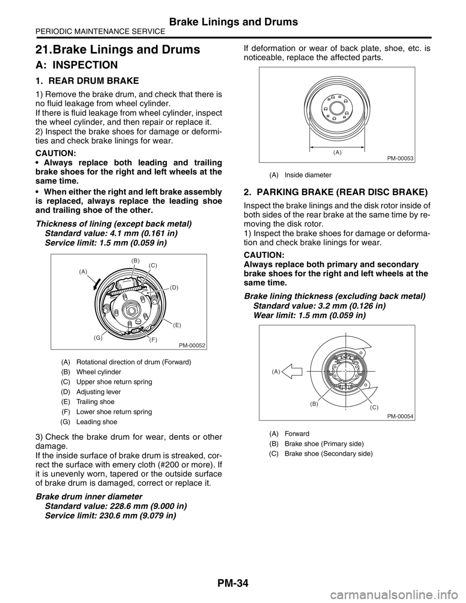
1) Remove the brake drum, and check that there is
no fluid leakage from wheel cylinder.
If there is fluid leakage from wheel cylinder, inspect
the wheel cylinder, and then repair or replace it.
2) Inspect the brake shoes for damage or deformi-
ties and check brake linings for wear.
CAUTION:
Always replace both leading and trailing
brake shoes for the right and left wheels at the
same time.
When either the right and left brake assembly
is replaced, always replace the leading shoe
and trailing shoe of the other.
Thickness of lining (except back metal)
Standard value: 4.1 mm (0.161 in)
Service limit: 1.5 mm (0.059 in)
3) Check the brake drum for wear, dents or other
damage.
If the inside surface of brake drum is streaked, cor-
rect the surface with emery cloth (#200 or more). If
it is unevenly worn, tapered or the outside surface
of brake drum is damaged, correct or replace it.
Brake drum inner diameter
Standard value: 228.6 mm (9.000 in)
Service limit: 230.6 mm (9.079 in)If deformation or wear of back plate, shoe, etc. is
noticeable, replace the affected parts.
2. PARKING BRAKE (REAR DISC BRAKE)
Inspect the brake linings and the disk rotor inside of
both sides of the rear brake at the same time by re-
moving the disk rotor.
1) Inspect the brake shoes for damage or deforma-
tion and check brake linings for wear.
CAUTION:
Always replace both primary and secondary
brake shoes for the right and left wheels at the
same time.
Brake lining thickness (excluding back metal)
Standard value: 3.2 mm (0.126 in)
Wear limit: 1.5 mm (0.059 in)
(A) Rotational direction of drum (Forward)
(B) Wheel cylinder
(C) Upper shoe return spring
(D) Adjusting lever
(E) Trailing shoe
(F) Lower shoe return spring
(G) Leading shoe
PM-00052
(B)
(C)
(D)
(E)
(F) (G) (A)
(A) Inside diameter
(A) Forward
(B) Brake shoe (Primary side)
(C) Brake shoe (Secondary side)
PM-00053(A)
PM-00054
(B)
(C) (A)
Page 772 of 2870
PM-35
PERIODIC MAINTENANCE SERVICE
Brake Linings and Drums
2) Check the disk rotor for wear, dents or other
damage. If the inside surface of disk rotor is
streaked, correct the surface with emery cloth
(#200 or more). If it is unevenly worn or tapered,
correct or replace it.
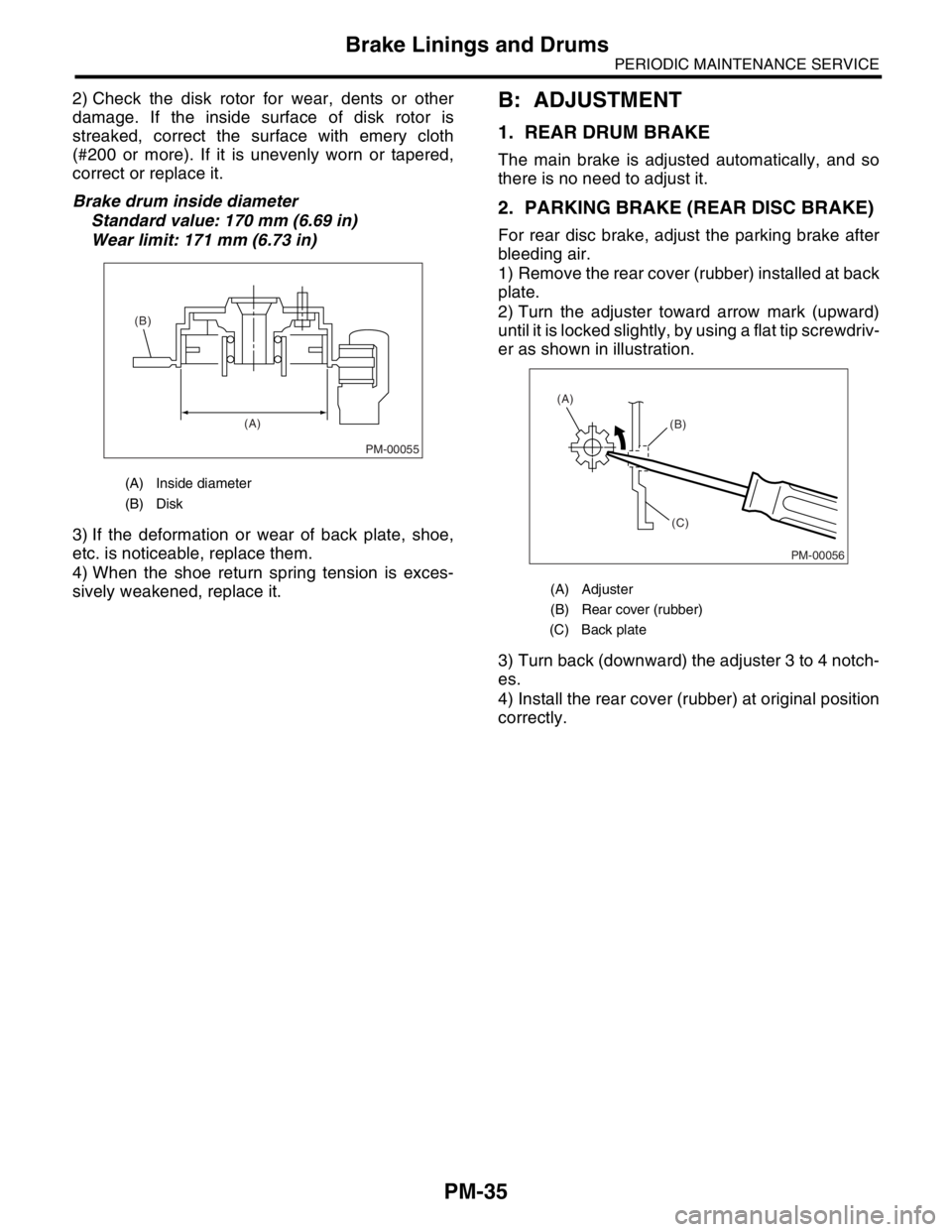
Brake drum inside diameter
Standard value: 170 mm (6.69 in)
Wear limit: 171 mm (6.73 in)
3) If the deformation or wear of back plate, shoe,
etc. is noticeable, replace them.
4) When the shoe return spring tension is exces-
sively weakened, replace it.B: ADJUSTMENT
1. REAR DRUM BRAKE
The main brake is adjusted automatically, and so
there is no need to adjust it.
2. PARKING BRAKE (REAR DISC BRAKE)
For rear disc brake, adjust the parking brake after
bleeding air.
1) Remove the rear cover (rubber) installed at back
plate.
2) Turn the adjuster toward arrow mark (upward)
until it is locked slightly, by using a flat tip screwdriv-
er as shown in illustration.
3) Turn back (downward) the adjuster 3 to 4 notch-
es.
4) Install the rear cover (rubber) at original position
correctly.
(A) Inside diameter
(B) Disk
PM-00055
(A) (B)
(A) Adjuster
(B) Rear cover (rubber)
(C) Back plate
PM-00056
(B)
(C) (A)