engine repair SUBARU FORESTER 2004 Service Repair Manual
[x] Cancel search | Manufacturer: SUBARU, Model Year: 2004, Model line: FORESTER, Model: SUBARU FORESTER 2004Pages: 2870, PDF Size: 38.67 MB
Page 2681 of 2870
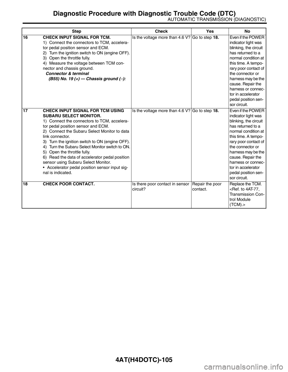
4AT(H4DOTC)-105
AUTOMATIC TRANSMISSION (DIAGNOSTIC)
Diagnostic Procedure with Diagnostic Trouble Code (DTC)
16 CHECK INPUT SIGNAL FOR TCM.
1) Connect the connectors to TCM, accelera-
tor pedal position sensor and ECM.
2) Turn the ignition switch to ON (engine OFF).
3) Open the throttle fully.
4) Measure the voltage between TCM con-
nector and chassis ground.
Connector & terminal
(B55) No. 19 (+) — Chassis ground (
−):Is the voltage more than 4.6 V? Go to step 18.Even if the POWER
indicator light was
blinking, the circuit
has returned to a
normal condition at
this time. A tempo-
rary poor contact of
the connector or
harness may be the
cause. Repair the
harness or connec-
tor in accelerator
pedal position sen-
sor circuit.
17 CHECK INPUT SIGNAL FOR TCM USING
SUBARU SELECT MONITOR.
1) Connect the connectors to TCM, accelera-
tor pedal position sensor and ECM.
2) Connect the Subaru Select Monitor to data
link connector.
3) Turn the ignition switch to ON (engine OFF).
4) Turn the Subaru Select Monitor switch to ON.
5) Open the throttle fully.
6) Read the data of accelerator pedal position
sensor using Subaru Select Monitor.
Accelerator pedal position sensor input sig-
nal is indicated.Is the voltage more than 4.6 V? Go to step 18.Even if the POWER
indicator light was
blinking, the circuit
has returned to a
normal condition at
this time. A tempo-
rary poor contact of
the connector or
harness may be the
cause. Repair the
harness or connec-
tor in accelerator
pedal position sen-
sor circuit.
18 CHECK POOR CONTACT.Is there poor contact in sensor
circuit?Repair the poor
contact.Replace the TCM.
trol Module
(TCM).> Step Check Yes No
Page 2694 of 2870
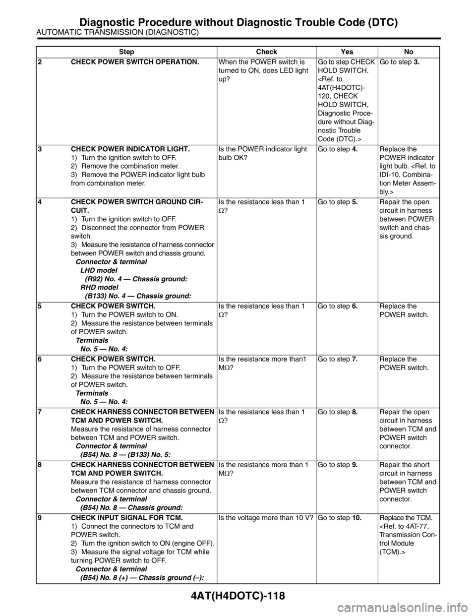
4AT(H4DOTC)-118
AUTOMATIC TRANSMISSION (DIAGNOSTIC)
Diagnostic Procedure without Diagnostic Trouble Code (DTC)
2 CHECK POWER SWITCH OPERATION.When the POWER switch is
turned to ON, does LED light
up?Go to step CHECK
HOLD SWITCH.
120, CHECK
HOLD SWITCH,
Diagnostic Proce-
dure without Diag-
nostic Trouble
Code (DTC).>Go to step 3.
3 CHECK POWER INDICATOR LIGHT.
1) Turn the ignition switch to OFF.
2) Remove the combination meter.
3) Remove the POWER indicator light bulb
from combination meter.Is the POWER indicator light
bulb OK?Go to step 4.Replace the
POWER indicator
light bulb.
tion Meter Assem-
bly.>
4 CHECK POWER SWITCH GROUND CIR-
CUIT.
1) Turn the ignition switch to OFF.
2) Disconnect the connector from POWER
switch.
3) Measure the resistance of harness connector
between POWER switch and chassis ground.
Connector & terminal
LHD model
(R92) No. 4 — Chassis ground:
RHD model
(B133) No. 4 — Chassis ground:Is the resistance less than 1
Ω?Go to step 5.Repair the open
circuit in harness
between POWER
switch and chas-
sis ground.
5 CHECK POWER SWITCH.
1) Turn the POWER switch to ON.
2) Measure the resistance between terminals
of POWER switch.
Te r m i n a l s
No. 5 — No. 4:Is the resistance less than 1
Ω?Go to step 6.Replace the
POWER switch.
6 CHECK POWER SWITCH.
1) Turn the POWER switch to OFF.
2) Measure the resistance between terminals
of POWER switch.
Te r m i n a l s
No. 5 — No. 4:Is the resistance more than1
MΩ?Go to step 7.Replace the
POWER switch.
7 CHECK HARNESS CONNECTOR BETWEEN
TCM AND POWER SWITCH.
Measure the resistance of harness connector
between TCM and POWER switch.
Connector & terminal
(B54) No. 8 — (B133) No. 5:Is the resistance less than 1
Ω?Go to step 8.Repair the open
circuit in harness
between TCM and
POWER switch
connector.
8 CHECK HARNESS CONNECTOR BETWEEN
TCM AND POWER SWITCH.
Measure the resistance of harness connector
between TCM connector and chassis ground.
Connector & terminal
(B54) No. 8 — Chassis ground:Is the resistance more than 1
MΩ?Go to step 9.Repair the short
circuit in harness
between TCM and
POWER switch
connector.
9 CHECK INPUT SIGNAL FOR TCM.
1) Connect the connectors to TCM and
POWER switch.
2) Turn the ignition switch to ON (engine OFF).
3) Measure the signal voltage for TCM while
turning POWER switch to OFF.
Connector & terminal
(B54) No. 8 (+) — Chassis ground (–):Is the voltage more than 10 V? Go to step 10.Replace the TCM.
trol Module
(TCM).> Step Check Yes No
Page 2701 of 2870
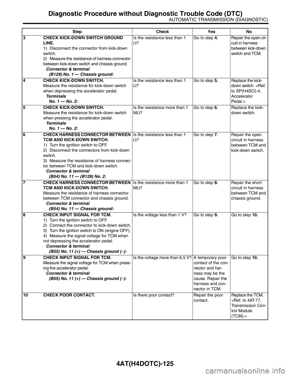
4AT(H4DOTC)-125
AUTOMATIC TRANSMISSION (DIAGNOSTIC)
Diagnostic Procedure without Diagnostic Trouble Code (DTC)
3 CHECK KICK-DOWN SWITCH GROUND
LINE.
1) Disconnect the connector from kick-down
switch.
2) Measure the resistance of harness connector
between kick-down switch and chassis ground.
Connector & terminal
(B129) No. 1 — Chassis ground:Is the resistance less than 1
Ω?Go to step 4.Repair the open cir-
cuit in harness
between kick-down
switch and TCM.
4 CHECK KICK-DOWN SWITCH.
Measure the resistance for kick-down switch
when depressing the accelerator pedal.
Te r m i n a l s
No. 1 — No. 2:Is the resistance less than 1
Ω?Go to step 5.Replace the kick-
down switch.
Accelerator
Pedal.>
5 CHECK KICK-DOWN SWITCH.
Measure the resistance for kick-down switch
when pressing the accelerator pedal.
Te r m i n a l s
No. 1 — No. 2:Is the resistance more than 1
MΩ?Go to step 6.Replace the kick-
down switch.
6 CHECK HARNESS CONNECTOR BETWEEN
TCM AND KICK-DOWN SWITCH.
1) Turn the ignition switch to OFF.
2) Disconnect the connectors from kick-down
switch.
3) Measure the resistance of harness connec-
tor between TCM and kick-down switch.
Connector & terminal
(B54) No. 11 — (B129) No. 2:Is the resistance less than 1
Ω?Go to step 7.Repair the open
circuit in harness
between TCM and
kick-down switch.
7 CHECK HARNESS CONNECTOR BETWEEN
TCM AND KICK-DOWN SWITCH.
Measure the resistance of harness connector
between TCM connector and chassis ground.
Connector & terminal
(B54) No. 11 — Chassis ground:Is the resistance more than 1
MΩ?Go to step 8.Repair the short
circuit in harness
between TCM and
chassis ground.
8 CHECK INPUT SIGNAL FOR TCM.
1) Turn the ignition switch to OFF.
2) Connect the connector to kick-down switch.
3) Turn the ignition switch to ON (engine OFF).
4) Measure the signal voltage for TCM when
not depressing the accelerator pedal.
Connector & terminal
(B55) No. 11 (+) — Chassis ground (
−):Is the voltage less than 1 V? Go to step 9.Go to step 10.
9 CHECK INPUT SIGNAL FOR TCM.
Measure the signal voltage for TCM when press-
ing the accelerator pedal.
Connector & terminal
(B55) No. 11 (+) — Chassis ground (
−):Is the voltage more than 6.5 V? A temporary poor
contact of the con-
nector and har-
ness may be the
cause. Repair the
harness and con-
nector in TCM.Go to step 10.
10 CHECK POOR CONTACT.Is there poor contact? Repair the poor
contact.Replace the TCM.
trol Module
(TCM).> Step Check Yes No
Page 2843 of 2870
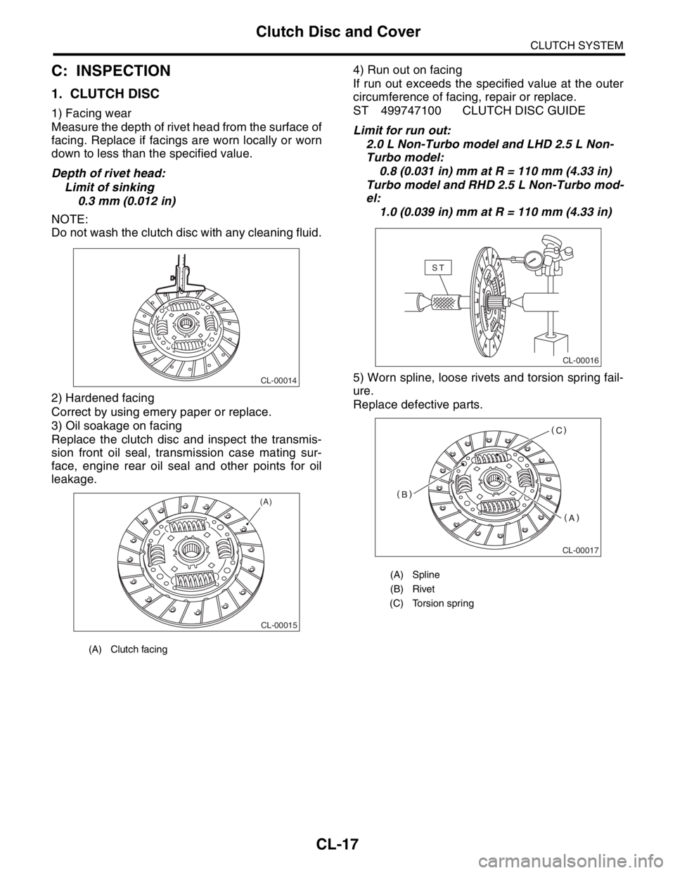
CL-17
CLUTCH SYSTEM
Clutch Disc and Cover
C: INSPECTION
1. CLUTCH DISC
1) Facing wear
Measure the depth of rivet head from the surface of
facing. Replace if facings are worn locally or worn
down to less than the specified value.
Depth of rivet head:
Limit of sinking
0.3 mm (0.012 in)
NOTE:
Do not wash the clutch disc with any cleaning fluid.
2) Hardened facing
Correct by using emery paper or replace.
3) Oil soakage on facing
Replace the clutch disc and inspect the transmis-
sion front oil seal, transmission case mating sur-
face, engine rear oil seal and other points for oil
leakage.4) Run out on facing
If run out exceeds the specified value at the outer
circumference of facing, repair or replace.
ST 499747100 CLUTCH DISC GUIDE
Limit for run out:
2.0 L Non-Turbo model and LHD 2.5 L Non-
Turbo model:
0.8 (0.031 in) mm at R = 110 mm (4.33 in)
Turbo model and RHD 2.5 L Non-Turbo mod-
el:
1.0 (0.039 in) mm at R = 110 mm (4.33 in)
5) Worn spline, loose rivets and torsion spring fail-
ure.
Replace defective parts.
(A) Clutch facing
CL-00014
CL-00015
(A)
(A) Spline
(B) Rivet
(C) Torsion spring
CL-00016
ST
CL-00017