coolant level SUBARU FORESTER 2004 Service Repair Manual
[x] Cancel search | Manufacturer: SUBARU, Model Year: 2004, Model line: FORESTER, Model: SUBARU FORESTER 2004Pages: 2870, PDF Size: 38.67 MB
Page 63 of 2870
AC-7
HVAC SYSTEM (AUTO A/C)(DIAGNOSTIC)
Auto A/C Control Module I/O Signal
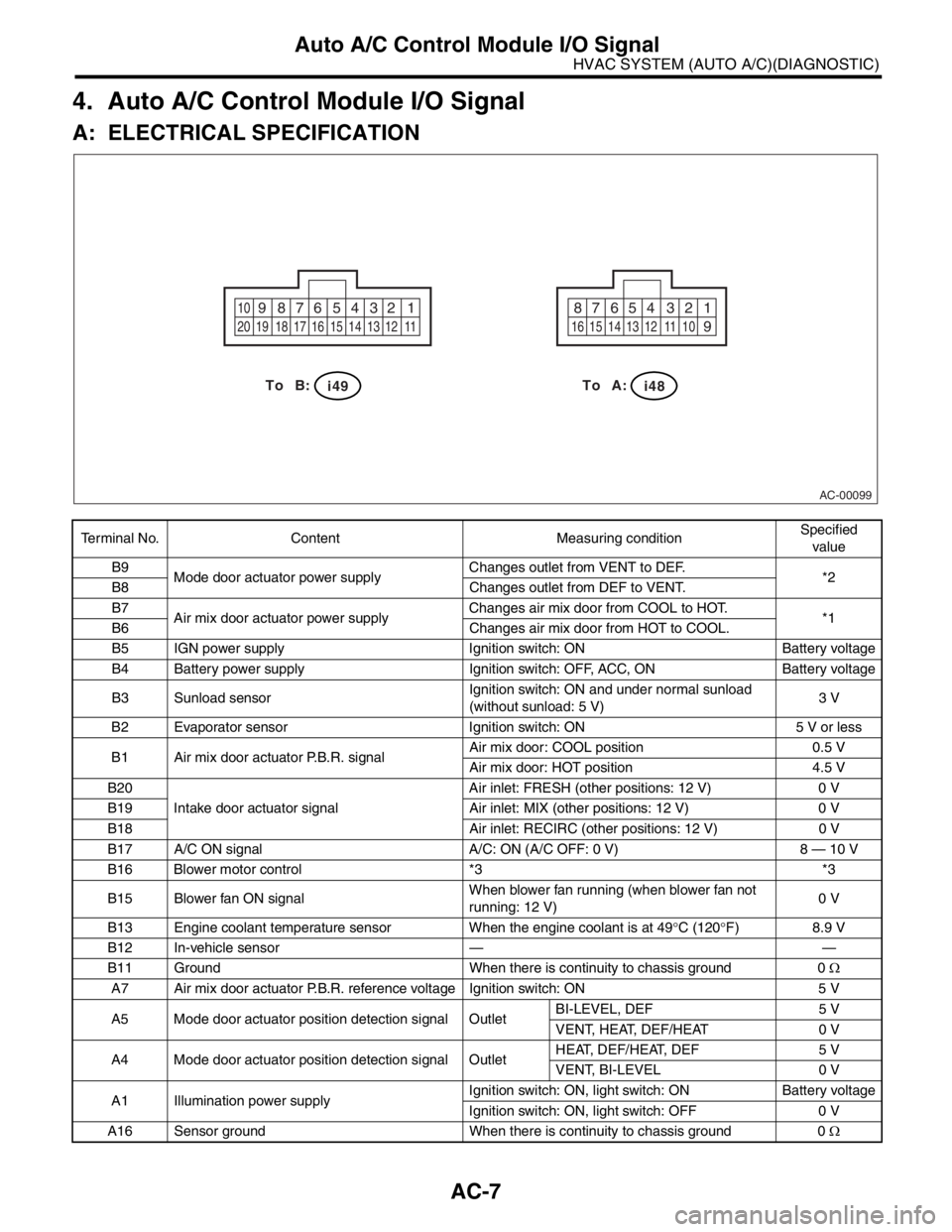
4. Auto A/C Control Module I/O Signal
A: ELECTRICAL SPECIFICATION
Terminal No. Content Measuring conditionSpecified
value
B9
Mode door actuator power supplyChanges outlet from VENT to DEF.
*2
B8 Changes outlet from DEF to VENT.
B7
Air mix door actuator power supplyChanges air mix door from COOL to HOT.
*1
B6 Changes air mix door from HOT to COOL.
B5 IGN power supply Ignition switch: ON Battery voltage
B4 Battery power supply Ignition switch: OFF, ACC, ON Battery voltage
B3 Sunload sensorIgnition switch: ON and under normal sunload
(without sunload: 5 V)3 V
B2 Evaporator sensor Ignition switch: ON 5 V or less
B1 Air mix door actuator P.B.R. signalAir mix door: COOL position 0.5 V
Air mix door: HOT position 4.5 V
B20
Intake door actuator signalAir inlet: FRESH (other positions: 12 V) 0 V
B19 Air inlet: MIX (other positions: 12 V) 0 V
B18 Air inlet: RECIRC (other positions: 12 V) 0 V
B17 A/C ON signal A/C: ON (A/C OFF: 0 V) 8 — 10 V
B16 Blower motor control *3 *3
B15 Blower fan ON signalWhen blower fan running (when blower fan not
running: 12 V)0 V
B13 Engine coolant temperature sensor When the engine coolant is at 49°C (120°F) 8.9 V
B12 In-vehicle sensor — —
B11 Ground When there is continuity to chassis ground 0 Ω
A7 Air mix door actuator P.B.R. reference voltage Ignition switch: ON 5 V
A5 Mode door actuator position detection signal OutletBI-LEVEL, DEF 5 V
VENT, HEAT, DEF/HEAT 0 V
A4 Mode door actuator position detection signal OutletHEAT, DEF/HEAT, DEF 5 V
VENT, BI-LEVEL 0 V
A1 Illumination power supplyIgnition switch: ON, light switch: ON Battery voltage
Ignition switch: ON, light switch: OFF 0 V
A16 Sensor ground When there is continuity to chassis ground 0 Ω
AC-00099
1 2 3 4 5 6 7 8 910
11 12 13 14 15 16 17 18 19 201 2 3 4 5 6 7 8
9
10 11 12 13 14 15 16
i48B: To A:To
i49
Page 388 of 2870

IDI-4
INSTRUMENTATION/DRIVER INFO
Combination Meter System
B: INSPECTION
CAUTION:
When measuring voltage and resistance of the ECM, TCM, or each sensor, use a tapered pin with a
diameter of less than 0.64 mm (0.025 in) in order to avoid poor contact. Do not insert the pin more
than 2 mm (0.08 in).
1. SYMPTOM CHART
Symptom Repair order Reference
Combination meter assembly does not operate. (1) Power supply
(2) Ground circuit
GROUND CIRCUIT,
INSPECTION, Combi-
nation Meter System.>
Speedometer does not operate. (1) (MT model) Vehicle speed sensor
(AT model) TCM
(2) Harness
(3) SpeedometerMT model:
SPEED SENSOR,
INSPECTION, Combi-
nation Meter System.>
AT model:
SION CONTROL MOD-
ULE (TCM),
INSPECTION, Combi-
nation Meter System.>
Tachometer does not operate. (1) ECM
(2) Harness
(3) Tachometer
MODULE (ECM),
INSPECTION, Combi-
nation Meter System.>
Fuel gauge does not operate. (1) Fuel level sensor
(2) Harness
(3) Fuel gauge
SOR, INSPECTION,
Combination Meter
System.>
Water temperature gauge does not operate. (1) Engine coolant temperature sensor
(2) Harness
(3) Water temperature gauge
TEMPERATURE SEN-
SOR, INSPECTION,
Combination Meter
System.>
Outside temperature indicator does not operate. (1) Ambient sensor
(2) Harness
(3) Combination meter
TURE INDICATOR,
INSPECTION, Combi-
nation Meter System.>
Page 392 of 2870

IDI-8
INSTRUMENTATION/DRIVER INFO
Combination Meter System
7. CHECK ENGINE COOLANT TEMPERATURE SENSOR
8. CHECK OUTSIDE TEMPERATURE INDICATOR
4 CHECK HARNESS BETWEEN FUEL LEVEL
SENSOR AND FUEL SUB LEVEL SENSOR.
Measure the resistance between fuel level sen-
sor harness connector terminal and fuel sub
level sensor harness connector terminal.
Connector & terminal
(R58) No. 3 — (R59) No. 2:Is the resistance less than 10
Ω?Go to step 5.Repair the wiring
harness.
5 CHECK FUEL LEVEL SENSOR GROUND
CIRCUIT.
Measure the resistance between fuel level sen-
sor harness connector terminal and chassis
ground.
Connector & terminal
(R58) No. 5 — Chassis ground:Is the resistance less than 10
Ω?Check the fuel
gauge.
TION, Fuel
Gauge.>Repair the wiring
harness.
Step Check Yes No
1 CHECK ENGINE COOLANT TEMPERATURE
SENSOR.
Check the engine coolant temperature sensor.
ture sensor OK?Go to step 2.Replace the
engine coolant
temperature sen-
sor.
2 CHECK HARNESS BETWEEN ENGINE
COOLANT TEMPERATURE SENSOR AND
COMBINATION METER.
1) Turn the ignition switch to OFF.
2) Disconnect the connector from engine cool-
ant temperature sensor and combination
meter.
3) Measure the resistance between engine
coolant temperature sensor harness connector
and combination meter harness connector.
Connector & terminal
(E8) No. 3 — (i11) No. 10:Is the resistance less than 10
Ω?Go to step 3.Repair the wiring
harness.
3 CHECK WATER TEMPERATURE GAUGE
GROUND CIRCUIT.
Measure the resistance between combination
meter harness connector terminal and chassis
ground.
Connector & terminal
(i11) No. 9 — Chassis ground:Is the resistance less than 10
Ω?Check the water
temperature
gauge.
TION, Water Tem-
perature Gauge.>Repair the wiring
harness.
Step Check Yes No
1 CHECK POWER SUPPLY FOR AMBIENT
SENSOR.
1) Turn the ignition switch to OFF.
2) Disconnect the connector from outside
temperature sensor.
3) Turn the ignition switch to ON.
4) Measure the voltage between outside tem-
perature sensor harness connector terminal
and chassis ground.
Connector & terminal
(F78) No. 2 (+) — Chassis ground (
−):Is the voltage more than 4 V? Go to step 3.Go to step 2. Step Check Yes No
Page 732 of 2870
PI-9
PRE-DELIVERY INSPECTION
Pre-delivery Inspection
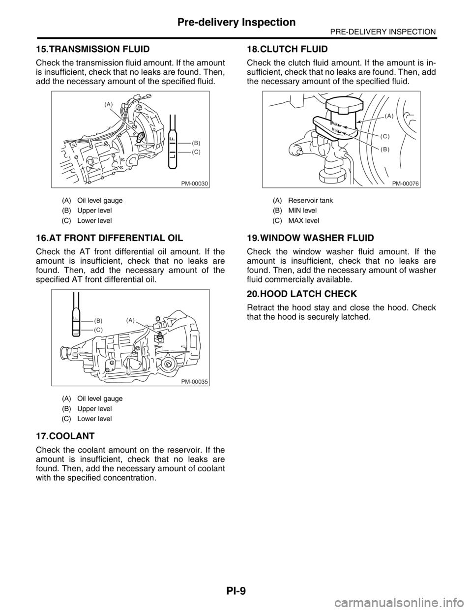
15.TRANSMISSION FLUID
Check the transmission fluid amount. If the amount
is insufficient, check that no leaks are found. Then,
add the necessary amount of the specified fluid.
16.AT FRONT DIFFERENTIAL OIL
Check the AT front differential oil amount. If the
amount is insufficient, check that no leaks are
found. Then, add the necessary amount of the
specified AT front differential oil.
17.COOLANT
Check the coolant amount on the reservoir. If the
amount is insufficient, check that no leaks are
found. Then, add the necessary amount of coolant
with the specified concentration.
18.CLUTCH FLUID
Check the clutch fluid amount. If the amount is in-
sufficient, check that no leaks are found. Then, add
the necessary amount of the specified fluid.
19.WINDOW WASHER FLUID
Check the window washer fluid amount. If the
amount is insufficient, check that no leaks are
found. Then, add the necessary amount of washer
fluid commercially available.
20.HOOD LATCH CHECK
Retract the hood stay and close the hood. Check
that the hood is securely latched.
(A) Oil level gauge
(B) Upper level
(C) Lower level
(A) Oil level gauge
(B) Upper level
(C) Lower level
PM-00030
(B)
(C) (A)
PM-00035
(B)
(C)(A)
(A) Reservoir tank
(B) MIN level
(C) MAX level
PM-00076
(A)
(B) (C)
Page 735 of 2870
PI-12
PRE-DELIVERY INSPECTION
Pre-delivery Inspection
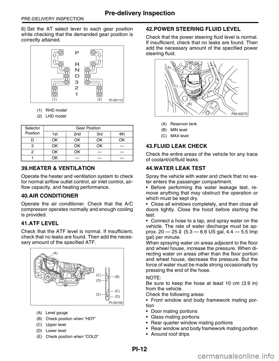
6) Set the AT select lever to each gear position
while checking that the demanded gear position is
correctly attained.
39.HEATER & VENTILATION
Operate the heater and ventilation system to check
for normal airflow outlet control, air inlet control, air-
flow capacity, and heating performance.
40.AIR CONDITIONER
Operate the air conditioner. Check that the A/C
compressor operates normally and enough cooling
is provided.
41.ATF LEVEL
Check that the ATF level is normal. If insufficient,
check that no leaks are found. Then add the neces-
sary amount of the specified ATF.
42.POWER STEERING FLUID LEVEL
Check that the power steering fluid level is normal.
If insufficient, check that no leaks are found. Then
add the necessary amount of the specified power
steering fluid.
43.FLUID LEAK CHECK
Check the entire areas of the vehicle for any trace
of coolant/oil/fluid leaks.
44.WATER LEAK TEST
Spray the vehicle with water and check that no wa-
ter enters the passenger compartment.
Before performing the water leakage test, re-
move anything that may obstruct the operation or
which must be kept dry.
Close all windows completely, and then close all
doors tightly. Close the hood before starting the
test.
Connect a hose to a tap, and spray water on the
vehicle. The rate of water discharge must be ap-
prox. 20 — 252 (5.3 — 6.6 US gal, 4.4 — 5.5 Imp
gal) per minute.
When spraying water on areas adjacent to the floor
and wheel house, increase the pressure. When di-
recting water on areas other than the floor portion
and wheel house, decrease the pressure. But the
force of water must be made strong occasionally by
pressing the end of the hose.
NOTE:
Be sure to keep the hose at least 10 cm (3.9 in)
from the vehicle.
Check the following areas:
Front window and body framework mating por-
tion
Door mating portions
Glass mating portions
Rear quarter window mating portions
Rear window and body framework mating portion
Around roof drips
(1) RHD model
(2) LHD model
Selector
Po si t io nGear Position
1st 2nd 3rd 4th
D OKOKOKOK
3 OKOKOK —
2OKOK——
1OK———
(A) Level gauge
(B) Check position when “HOT”
(C) Upper level
(D) Lower level
(E) Check position when “COLD”
PI-00112(1) (2)
P
R
N
D
3
2
1
PI-00105
COLD
LFHOT LF
(A)
(C)
(D)
(C)
(D)
(E)
(B)
(A) Reservoir tank
(B) MIN level
(C) MAX level
PM-00070
(A)
(C)
(B)
Page 758 of 2870
PM-21
PERIODIC MAINTENANCE SERVICE
Engine Coolant
12.Engine Coolant
A: REPLACEMENT
1. REPLACEMENT OF ENGINE COOLANT
WARNING:
The radiator is of the pressurized type. Do not
attempt to open the radiator cap immediately
after the engine has been stopped.
1) Lift-up the vehicle.
2) Remove the under cover.
3) Place a container under drain pipe.
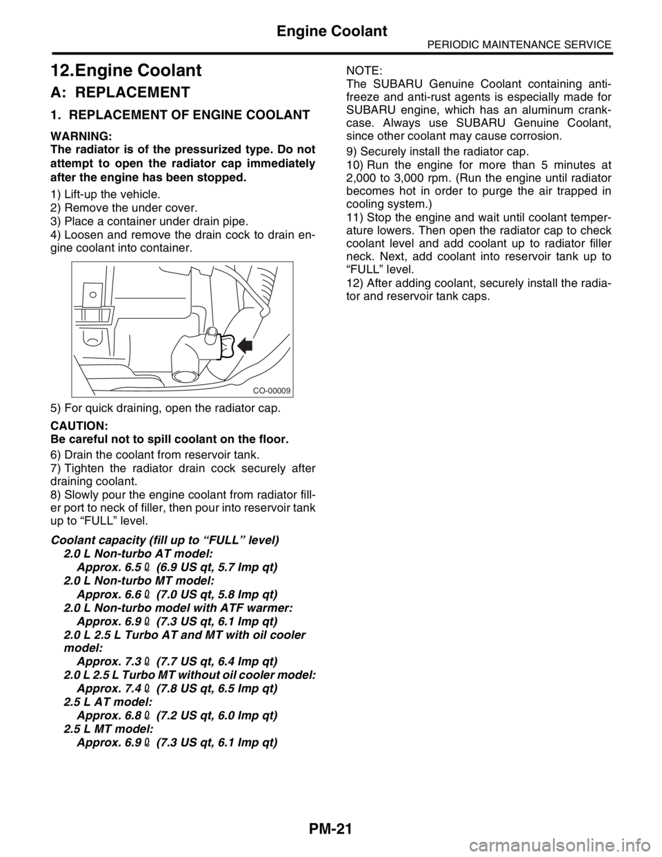
4) Loosen and remove the drain cock to drain en-
gine coolant into container.
5) For quick draining, open the radiator cap.
CAUTION:
Be careful not to spill coolant on the floor.
6) Drain the coolant from reservoir tank.
7) Tighten the radiator drain cock securely after
draining coolant.
8) Slowly pour the engine coolant from radiator fill-
er port to neck of filler, then pour into reservoir tank
up to “FULL” level.
Coolant capacity (fill up to “FULL” level)
2.0 L Non-turbo AT model:
Approx. 6.52 (6.9 US qt, 5.7 Imp qt)
2.0 L Non-turbo MT model:
Approx. 6.62 (7.0 US qt, 5.8 Imp qt)
2.0 L Non-turbo model with ATF warmer:
Approx. 6.92 (7.3 US qt, 6.1 Imp qt)
2.0 L 2.5 L Turbo AT and MT with oil cooler
model:
Approx. 7.32 (7.7 US qt, 6.4 Imp qt)
2.0 L 2.5 L Turbo MT without oil cooler model:
Approx. 7.42 (7.8 US qt, 6.5 Imp qt)
2.5 L AT model:
Approx. 6.82 (7.2 US qt, 6.0 Imp qt)
2.5 L MT model:
Approx. 6.92 (7.3 US qt, 6.1 Imp qt)NOTE:
The SUBARU Genuine Coolant containing anti-
freeze and anti-rust agents is especially made for
SUBARU engine, which has an aluminum crank-
case. Always use SUBARU Genuine Coolant,
since other coolant may cause corrosion.
9) Securely install the radiator cap.
10) Run the engine for more than 5 minutes at
2,000 to 3,000 rpm. (Run the engine until radiator
becomes hot in order to purge the air trapped in
cooling system.)
11) Stop the engine and wait until coolant temper-
ature lowers. Then open the radiator cap to check
coolant level and add coolant up to radiator filler
neck. Next, add coolant into reservoir tank up to
“FULL” level.
12) After adding coolant, securely install the radia-
tor and reservoir tank caps.
CO-00009
Page 783 of 2870

FUEL INJECTION (FUEL SYSTEM)
FU(H4SO)
Page
1. General Description ....................................................................................2
2. Throttle Body .............................................................................................13
3. Intake Manifold ..........................................................................................14
4. Engine Coolant Temperature Sensor........................................................25
5. Crankshaft Position Sensor.......................................................................26
6. Camshaft Position Sensor.........................................................................27
7. Knock Sensor ............................................................................................28
8. Throttle Position Sensor ............................................................................29
9. Manifold Absolute Pressure Sensor ..........................................................31
10. Intake Air Temperature Sensor .................................................................32
11. Idle Air Control Solenoid Valve .................................................................33
12. EGR Valve ................................................................................................34
13. Fuel Injector ..............................................................................................35
14. Front Oxygen (A/F) Sensor .......................................................................40
15. Rear Oxygen Sensor.................................................................................42
16. Engine Control Module (ECM) ..................................................................44
17. Main Relay ................................................................................................45
18. Fuel Pump Relay.......................................................................................46
19. Fuel ...........................................................................................................47
20. Fuel Tank ..................................................................................................48
21. Fuel Filler Pipe ..........................................................................................51
22. Fuel Pump .................................................................................................55
23. Fuel Level Sensor .....................................................................................57
24. Fuel Sub Level Sensor ..............................................................................58
25. Fuel Filter ..................................................................................................60
26. Fuel Cut Valve...........................................................................................61
27. Fuel Damper Valve ...................................................................................62
28. Fuel Delivery, Return and Evaporation Lines............................................63
29. Fuel System Trouble in General ...............................................................66
Page 909 of 2870
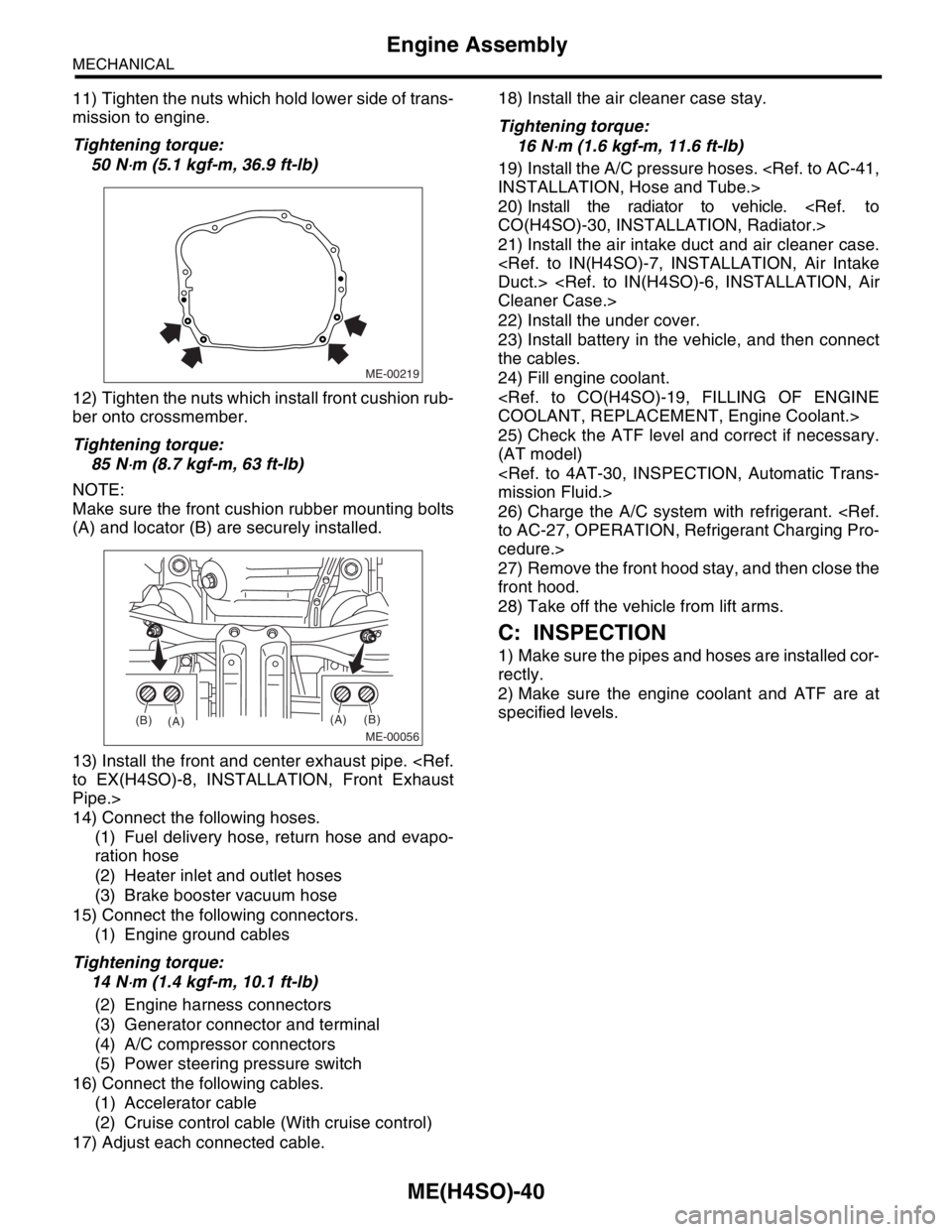
ME(H4SO)-40
MECHANICAL
Engine Assembly
11) Tighten the nuts which hold lower side of trans-
mission to engine.
Tightening torque:
50 N
⋅m (5.1 kgf-m, 36.9 ft-lb)
12) Tighten the nuts which install front cushion rub-
ber onto crossmember.
Tightening torque:
85 N
⋅m (8.7 kgf-m, 63 ft-lb)
NOTE:
Make sure the front cushion rubber mounting bolts
(A) and locator (B) are securely installed.
13) Install the front and center exhaust pipe.
Pipe.>
14) Connect the following hoses.
(1) Fuel delivery hose, return hose and evapo-
ration hose
(2) Heater inlet and outlet hoses
(3) Brake booster vacuum hose
15) Connect the following connectors.
(1) Engine ground cables
Tightening torque:
14 N
⋅m (1.4 kgf-m, 10.1 ft-lb)
(2) Engine harness connectors
(3) Generator connector and terminal
(4) A/C compressor connectors
(5) Power steering pressure switch
16) Connect the following cables.
(1) Accelerator cable
(2) Cruise control cable (With cruise control)
17) Adjust each connected cable.18) Install the air cleaner case stay.
Tightening torque:
16 N
⋅m (1.6 kgf-m, 11.6 ft-lb)
19) Install the A/C pressure hoses.
20) Install the radiator to vehicle.
21) Install the air intake duct and air cleaner case.
22) Install the under cover.
23) Install battery in the vehicle, and then connect
the cables.
24) Fill engine coolant.
25) Check the ATF level and correct if necessary.
(AT model)
26) Charge the A/C system with refrigerant.
cedure.>
27) Remove the front hood stay, and then close the
front hood.
28) Take off the vehicle from lift arms.
C: INSPECTION
1) Make sure the pipes and hoses are installed cor-
rectly.
2) Make sure the engine coolant and ATF are at
specified levels.
ME-00219
ME-00056
(A)
(A)(B)
(B)
Page 1002 of 2870
CO(H4SO)-19
COOLING
Engine Coolant
3. Engine Coolant
A: REPLACEMENT
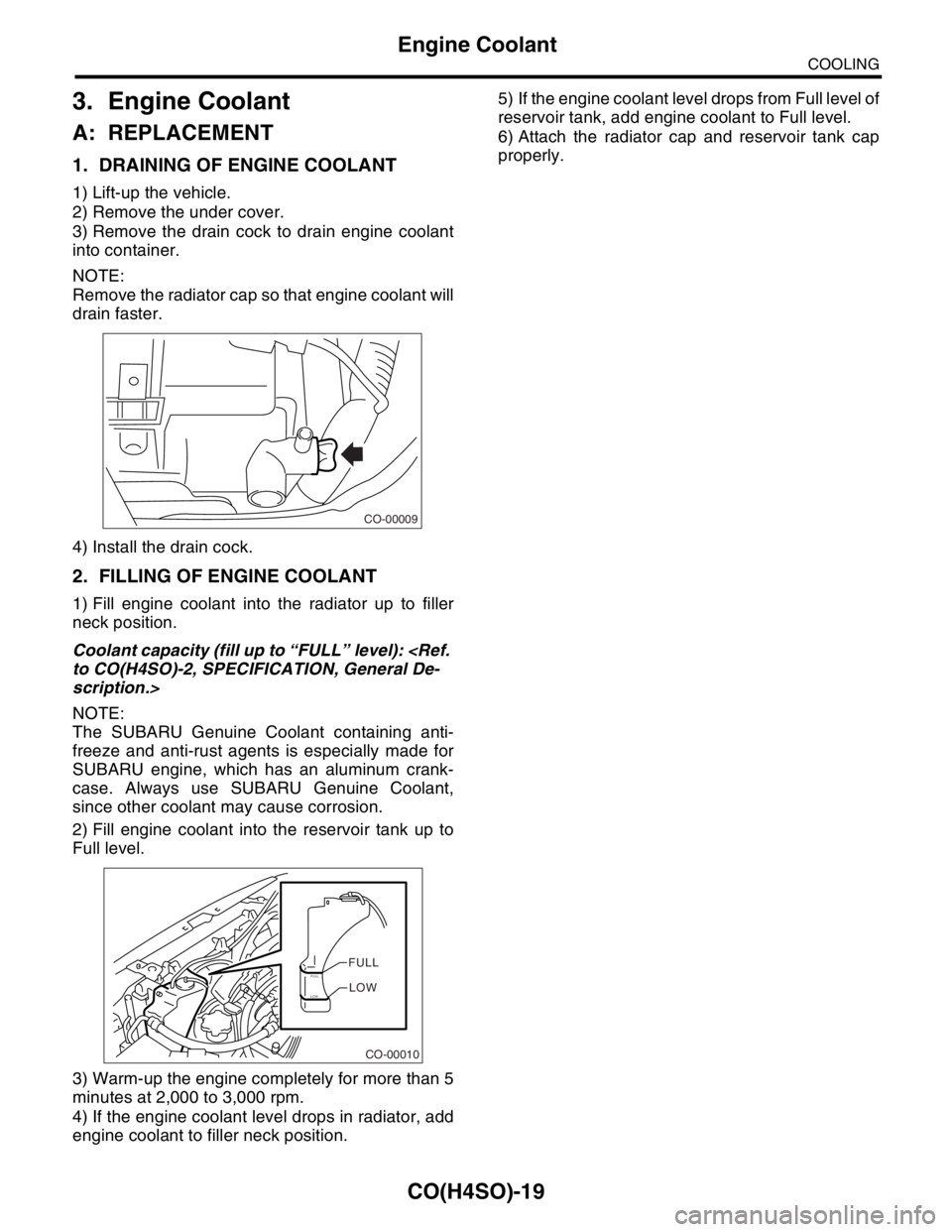
1. DRAINING OF ENGINE COOLANT
1) Lift-up the vehicle.
2) Remove the under cover.
3) Remove the drain cock to drain engine coolant
into container.
NOTE:
Remove the radiator cap so that engine coolant will
drain faster.
4) Install the drain cock.
2. FILLING OF ENGINE COOLANT
1) Fill engine coolant into the radiator up to filler
neck position.
Coolant capacity (fill up to “FULL” level):
scription.>
NOTE:
The SUBARU Genuine Coolant containing anti-
freeze and anti-rust agents is especially made for
SUBARU engine, which has an aluminum crank-
case. Always use SUBARU Genuine Coolant,
since other coolant may cause corrosion.
2) Fill engine coolant into the reservoir tank up to
Full level.
3) Warm-up the engine completely for more than 5
minutes at 2,000 to 3,000 rpm.
4) If the engine coolant level drops in radiator, add
engine coolant to filler neck position.5) If the engine coolant level drops from Full level of
reservoir tank, add engine coolant to Full level.
6) Attach the radiator cap and reservoir tank cap
properly.
CO-00009
CO-00010
FULLFULLLOWLOW
Page 1014 of 2870
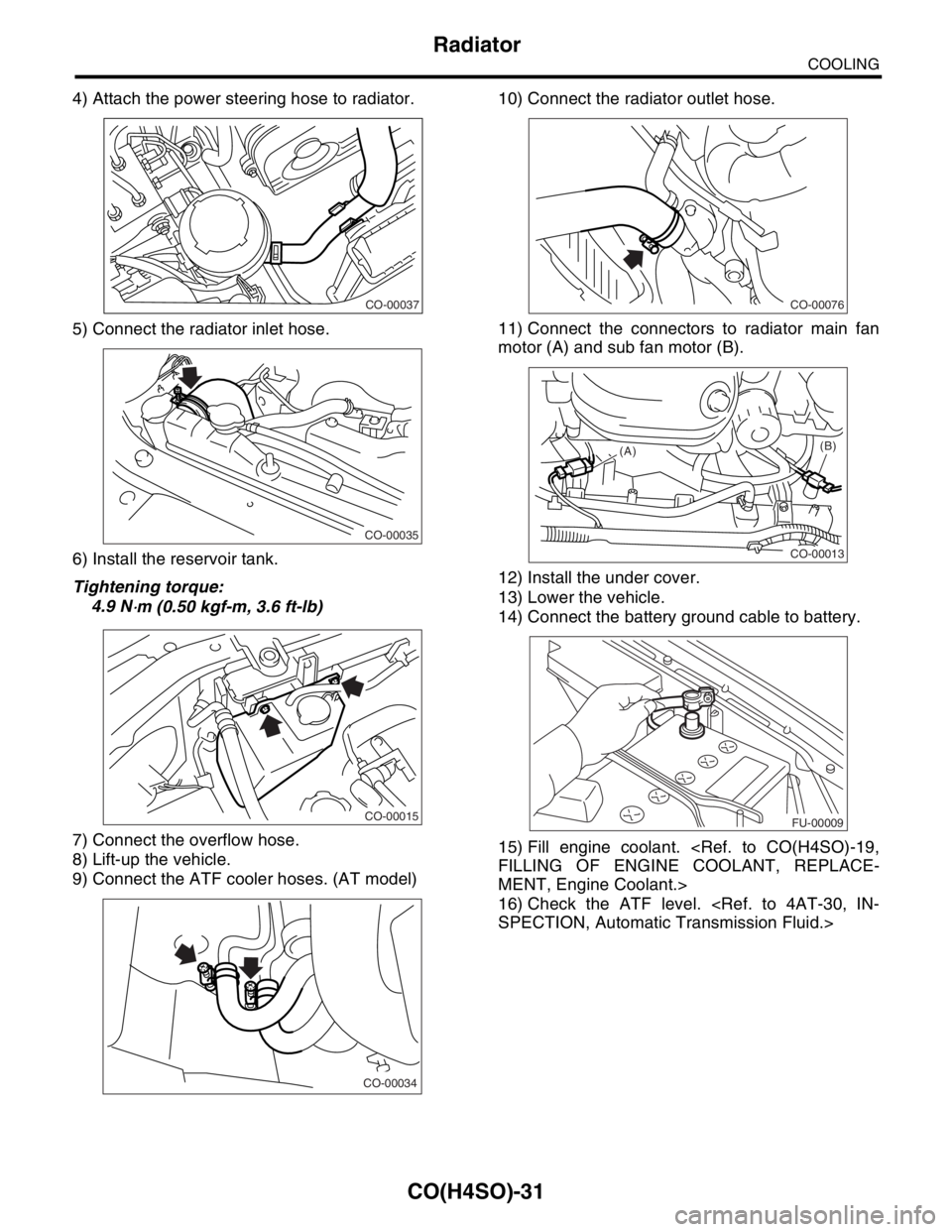
CO(H4SO)-31
COOLING
Radiator
4) Attach the power steering hose to radiator.
5) Connect the radiator inlet hose.
6) Install the reservoir tank.
Tightening torque:
4.9 N
⋅m (0.50 kgf-m, 3.6 ft-lb)
7) Connect the overflow hose.
8) Lift-up the vehicle.
9) Connect the ATF cooler hoses. (AT model)10) Connect the radiator outlet hose.
11) Connect the connectors to radiator main fan
motor (A) and sub fan motor (B).
12) Install the under cover.
13) Lower the vehicle.
14) Connect the battery ground cable to battery.
15) Fill engine coolant.
MENT, Engine Coolant.>
16) Check the ATF level.
CO-00037
CO-00035
CO-00015
CO-00034
CO-00076
CO-00013
(A)(B)
FU-00009