fuel tank removal SUBARU FORESTER 2004 Service Repair Manual
[x] Cancel search | Manufacturer: SUBARU, Model Year: 2004, Model line: FORESTER, Model: SUBARU FORESTER 2004Pages: 2870, PDF Size: 38.67 MB
Page 796 of 2870
FU(H4SO)-14
FUEL INJECTION (FUEL SYSTEM)
Intake Manifold
3. Intake Manifold
A: REMOVAL
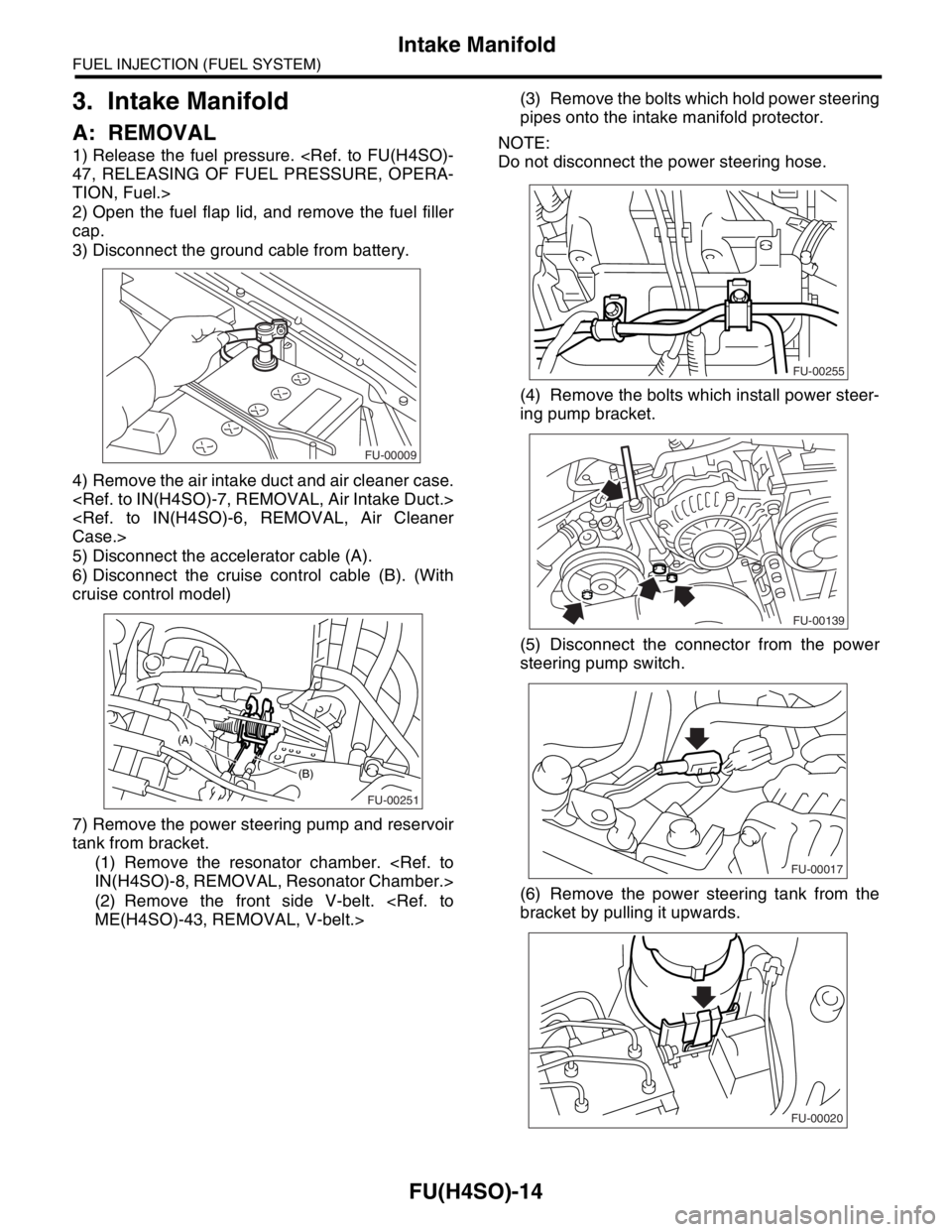
1) Release the fuel pressure.
TION, Fuel.>
2) Open the fuel flap lid, and remove the fuel filler
cap.
3) Disconnect the ground cable from battery.
4) Remove the air intake duct and air cleaner case.
5) Disconnect the accelerator cable (A).
6) Disconnect the cruise control cable (B). (With
cruise control model)
7) Remove the power steering pump and reservoir
tank from bracket.
(1) Remove the resonator chamber.
(2) Remove the front side V-belt.
pipes onto the intake manifold protector.
NOTE:
Do not disconnect the power steering hose.
(4) Remove the bolts which install power steer-
ing pump bracket.
(5) Disconnect the connector from the power
steering pump switch.
(6) Remove the power steering tank from the
bracket by pulling it upwards.
FU-00009
FU-00251
(B)
(A)
FU-00255
FU-00139
FU-00017
FU-00020
Page 817 of 2870
FU(H4SO)-35
FUEL INJECTION (FUEL SYSTEM)
Fuel Injector
13.Fuel Injector
A: REMOVAL
1. RH SIDE
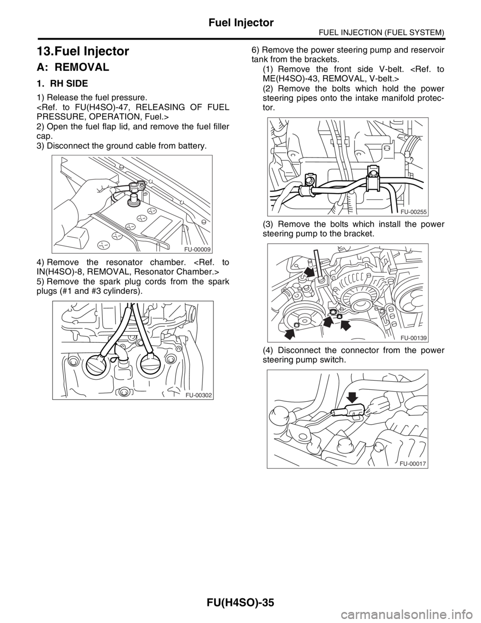
1) Release the fuel pressure.
2) Open the fuel flap lid, and remove the fuel filler
cap.
3) Disconnect the ground cable from battery.
4) Remove the resonator chamber.
5) Remove the spark plug cords from the spark
plugs (#1 and #3 cylinders).6) Remove the power steering pump and reservoir
tank from the brackets.
(1) Remove the front side V-belt.
(2) Remove the bolts which hold the power
steering pipes onto the intake manifold protec-
tor.
(3) Remove the bolts which install the power
steering pump to the bracket.
(4) Disconnect the connector from the power
steering pump switch.
FU-00009
FU-00302
FU-00255
FU-00139
FU-00017
Page 830 of 2870
FU(H4SO)-48
FUEL INJECTION (FUEL SYSTEM)
Fuel Tank
20.Fuel Tank
A: REMOVAL
WARNING:
Place “NO FIRE” signs near the working area.
Be careful not to spill fuel.
1) Set the vehicle on a lift.
2) Release the fuel pressure.
TION, Fuel.>
3) Drain fuel from the fuel tank.
4) Remove the rear seat.
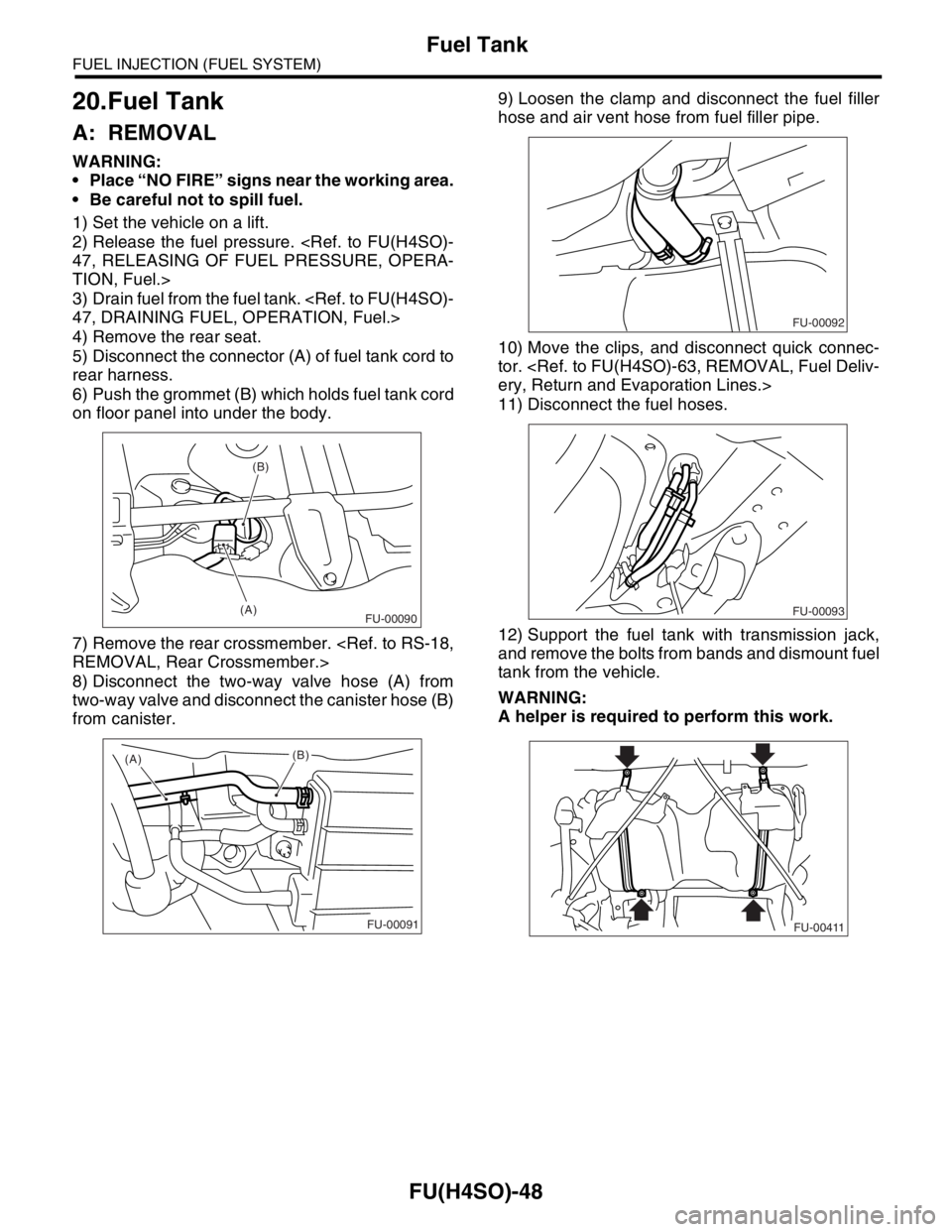
5) Disconnect the connector (A) of fuel tank cord to
rear harness.
6) Push the grommet (B) which holds fuel tank cord
on floor panel into under the body.
7) Remove the rear crossmember.
8) Disconnect the two-way valve hose (A) from
two-way valve and disconnect the canister hose (B)
from canister.9) Loosen the clamp and disconnect the fuel filler
hose and air vent hose from fuel filler pipe.
10) Move the clips, and disconnect quick connec-
tor.
11) Disconnect the fuel hoses.
12) Support the fuel tank with transmission jack,
and remove the bolts from bands and dismount fuel
tank from the vehicle.
WARNING:
A helper is required to perform this work.
(B)
(A)
FU-00090
(A)
(B)
FU-00091
FU-00092
FU-00093
FU-00411
Page 833 of 2870
FU(H4SO)-51
FUEL INJECTION (FUEL SYSTEM)
Fuel Filler Pipe
21.Fuel Filler Pipe
A: REMOVAL
WARNING:
Place “NO FIRE” signs near the working area.
Be careful not to spill fuel.
1) Set the vehicle on a lift.
2) Release the fuel pressure.
TION, Fuel.>
3) Open the fuel filler flap lid and remove fuel filler
cap.
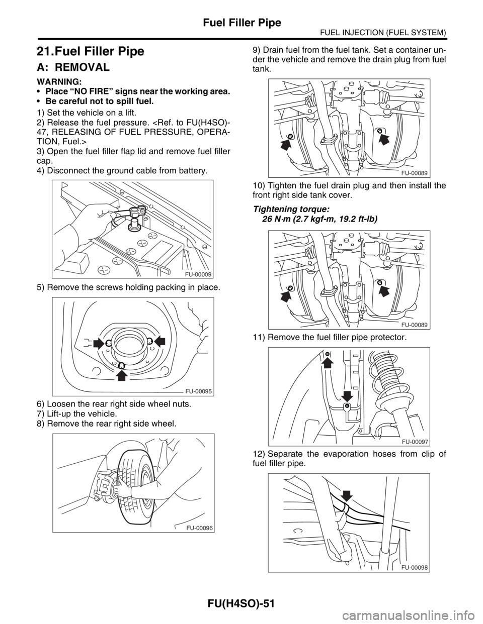
4) Disconnect the ground cable from battery.
5) Remove the screws holding packing in place.
6) Loosen the rear right side wheel nuts.
7) Lift-up the vehicle.
8) Remove the rear right side wheel.9) Drain fuel from the fuel tank. Set a container un-
der the vehicle and remove the drain plug from fuel
tank.
10) Tighten the fuel drain plug and then install the
front right side tank cover.
Tightening torque:
26 N
⋅m (2.7 kgf-m, 19.2 ft-lb)
11) Remove the fuel filler pipe protector.
12) Separate the evaporation hoses from clip of
fuel filler pipe.
FU-00009
FU-00095
FU-00096
FU-00089
FU-00089
FU-00097
FU-00098
Page 837 of 2870
FU(H4SO)-55
FUEL INJECTION (FUEL SYSTEM)
Fuel Pump
22.Fuel Pump
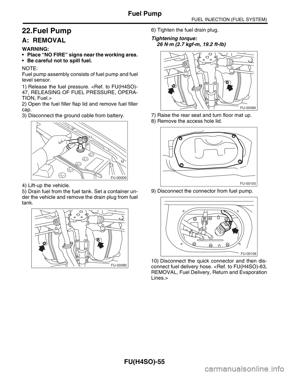
A: REMOVAL
WARNING:
Place “NO FIRE” signs near the working area.
Be careful not to spill fuel.
NOTE:
Fuel pump assembly consists of fuel pump and fuel
level sensor.
1) Release the fuel pressure.
TION, Fuel.>
2) Open the fuel filler flap lid and remove fuel filler
cap.
3) Disconnect the ground cable from battery.
4) Lift-up the vehicle.
5) Drain fuel from the fuel tank. Set a container un-
der the vehicle and remove the drain plug from fuel
tank.6) Tighten the fuel drain plug.
Tightening torque:
26 N
⋅m (2.7 kgf-m, 19.2 ft-lb)
7) Raise the rear seat and turn floor mat up.
8) Remove the access hole lid.
9) Disconnect the connector from fuel pump.
10) Disconnect the quick connector and then dis-
connect fuel delivery hose.
Lines.>
FU-00009
FU-00089
FU-00089
FU-00105
FU-00106
Page 838 of 2870
FU(H4SO)-56
FUEL INJECTION (FUEL SYSTEM)
Fuel Pump
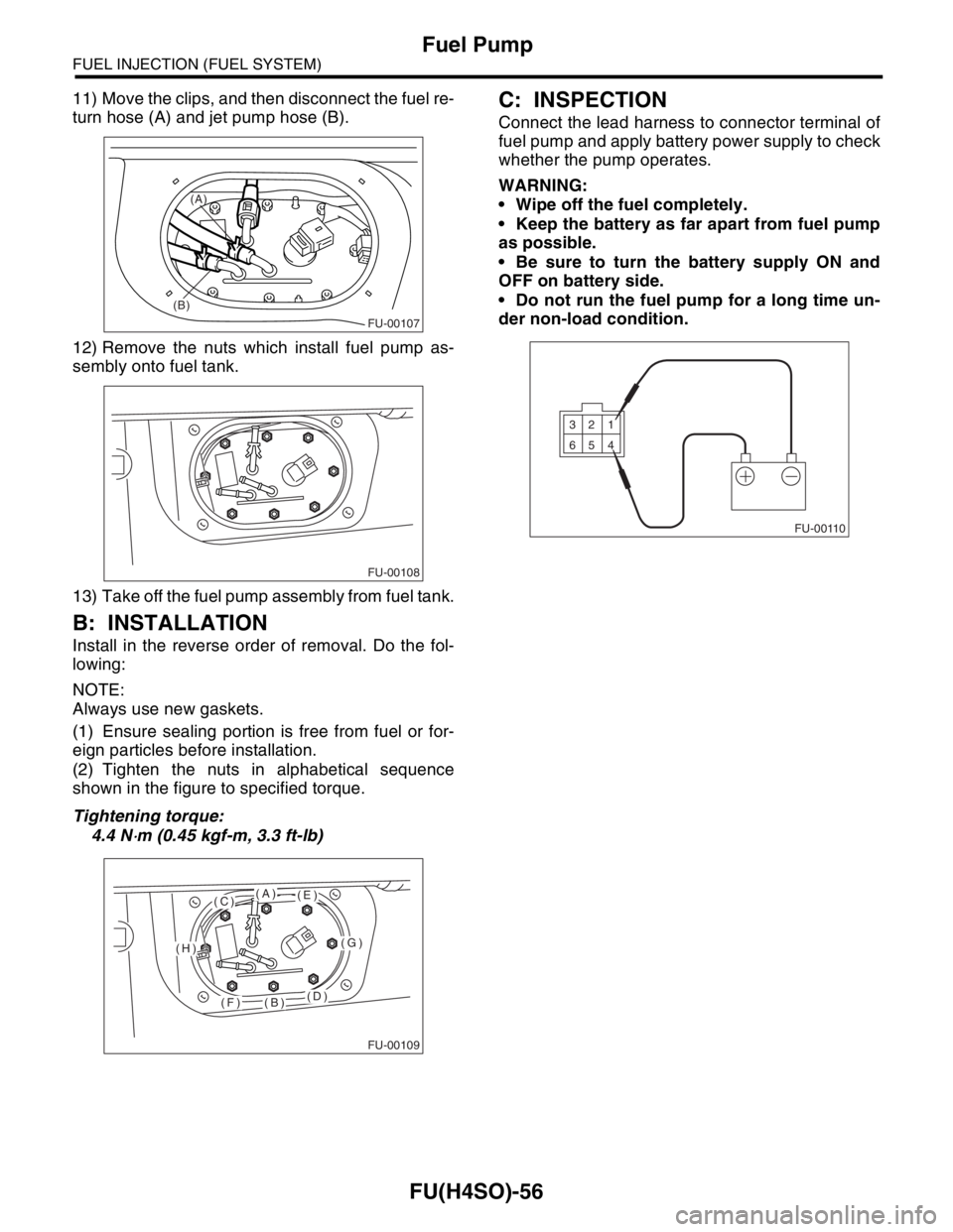
11) Move the clips, and then disconnect the fuel re-
turn hose (A) and jet pump hose (B).
12) Remove the nuts which install fuel pump as-
sembly onto fuel tank.
13) Take off the fuel pump assembly from fuel tank.
B: INSTALLATION
Install in the reverse order of removal. Do the fol-
lowing:
NOTE:
Always use new gaskets.
(1) Ensure sealing portion is free from fuel or for-
eign particles before installation.
(2) Tighten the nuts in alphabetical sequence
shown in the figure to specified torque.
Tightening torque:
4.4 N
⋅m (0.45 kgf-m, 3.3 ft-lb)
C: INSPECTION
Connect the lead harness to connector terminal of
fuel pump and apply battery power supply to check
whether the pump operates.
WARNING:
Wipe off the fuel completely.
Keep the battery as far apart from fuel pump
as possible.
Be sure to turn the battery supply ON and
OFF on battery side.
Do not run the fuel pump for a long time un-
der non-load condition.
FU-00107
(B)(A)
FU-00108
FU-00109
(A)
(B)
(C)
(D)
(E)
(F)
(G)(H)FU-00110
1 2 3
4 5 6
Page 840 of 2870
FU(H4SO)-58
FUEL INJECTION (FUEL SYSTEM)
Fuel Sub Level Sensor
24.Fuel Sub Level Sensor
A: REMOVAL
WARNING:
Place “NO FIRE” signs near the working area.
Be careful not to spill fuel.
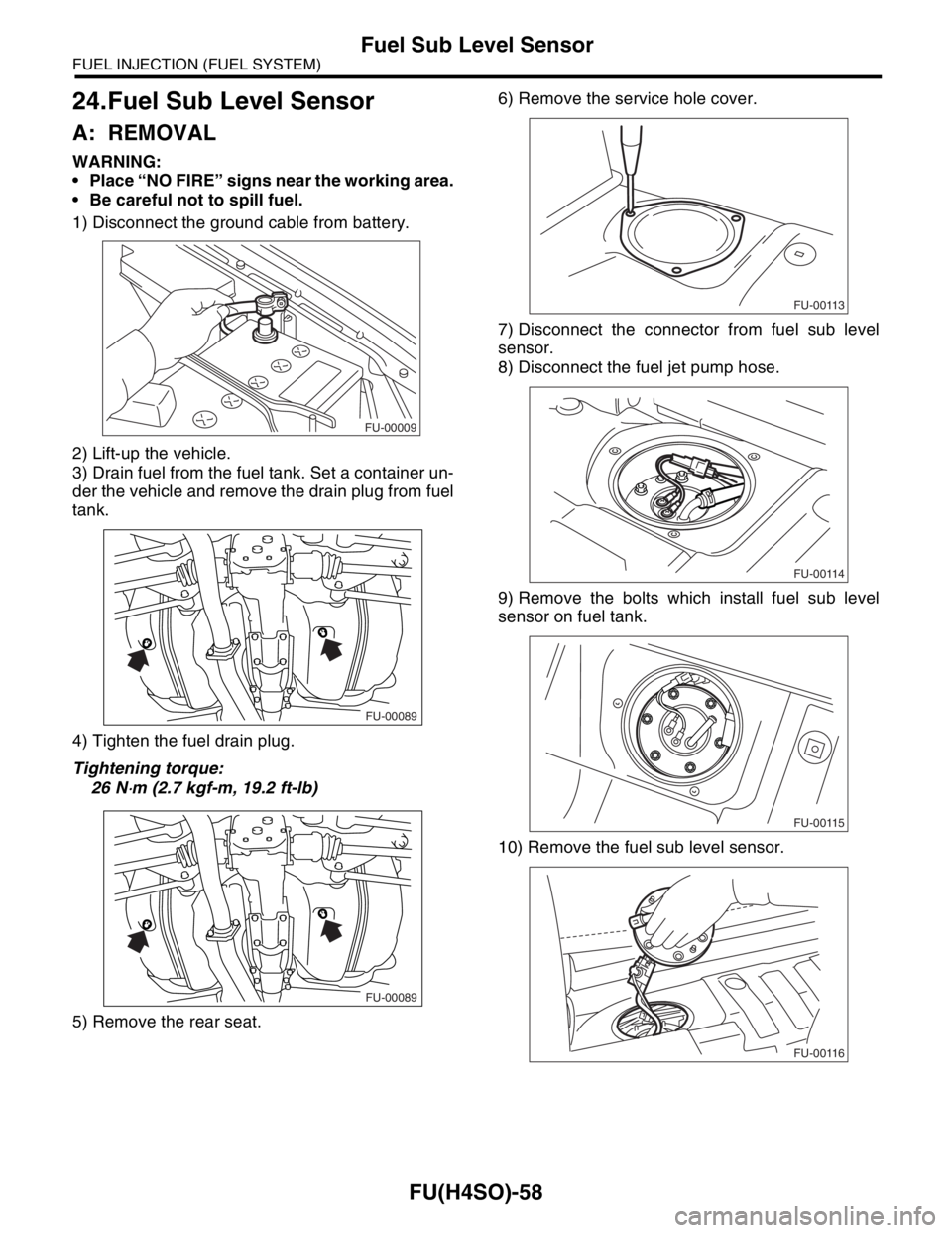
1) Disconnect the ground cable from battery.
2) Lift-up the vehicle.
3) Drain fuel from the fuel tank. Set a container un-
der the vehicle and remove the drain plug from fuel
tank.
4) Tighten the fuel drain plug.
Tightening torque:
26 N
⋅m (2.7 kgf-m, 19.2 ft-lb)
5) Remove the rear seat.6) Remove the service hole cover.
7) Disconnect the connector from fuel sub level
sensor.
8) Disconnect the fuel jet pump hose.
9) Remove the bolts which install fuel sub level
sensor on fuel tank.
10) Remove the fuel sub level sensor.
FU-00009
FU-00089
FU-00089
FU-00113
FU-00114
FU-00115
FU-00116
Page 843 of 2870
FU(H4SO)-61
FUEL INJECTION (FUEL SYSTEM)
Fuel Cut Valve
26.Fuel Cut Valve
A: REMOVAL
WARNING:
Place “NO FIRE” signs near the working area.
Be careful not to spill fuel.
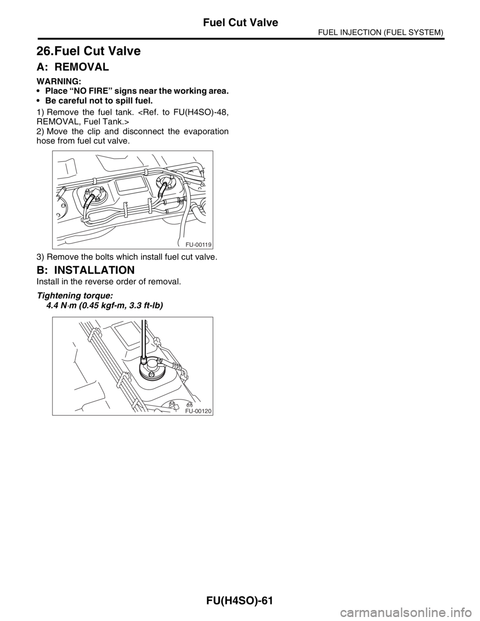
1) Remove the fuel tank.
2) Move the clip and disconnect the evaporation
hose from fuel cut valve.
3) Remove the bolts which install fuel cut valve.
B: INSTALLATION
Install in the reverse order of removal.
Tightening torque:
4.4 N
⋅m (0.45 kgf-m, 3.3 ft-lb)
FU-00119
FU-00120
Page 1369 of 2870
FU(H4DOTC)-14
FUEL INJECTION (FUEL SYSTEM)
Intake Manifold
3. Intake Manifold
A: REMOVAL
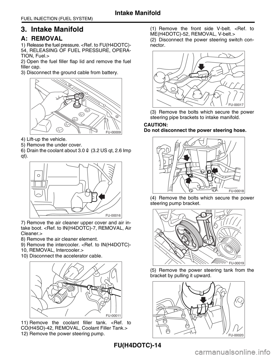
1) Release the fuel pressure.
TION, Fuel.>
2) Open the fuel filler flap lid and remove the fuel
filler cap.
3) Disconnect the ground cable from battery.
4) Lift-up the vehicle.
5) Remove the under cover.
6) Drain the coolant about 3.02 (3.2 US qt, 2.6 Imp
qt).
7) Remove the air cleaner upper cover and air in-
take boot.
8) Remove the air cleaner element.
9) Remove the intercooler.
10) Disconnect the accelerator cable.
11) Remove the coolant filler tank.
12) Remove the power steering pump.(1) Remove the front side V-belt.
(2) Disconnect the power steering switch con-
nector.
(3) Remove the bolts which secure the power
steering pipe brackets to intake manifold.
CAUTION:
Do not disconnect the power steering hose.
(4) Remove the bolts which secure the power
steering pump bracket.
(5) Remove the power steering tank from the
bracket by pulling it upward.
FU-00009
FU-00016
FU-00011
FU-00017
FU-00018
FU-00019
FU-00020
Page 1375 of 2870
FU(H4DOTC)-20
FUEL INJECTION (FUEL SYSTEM)
Intake Manifold
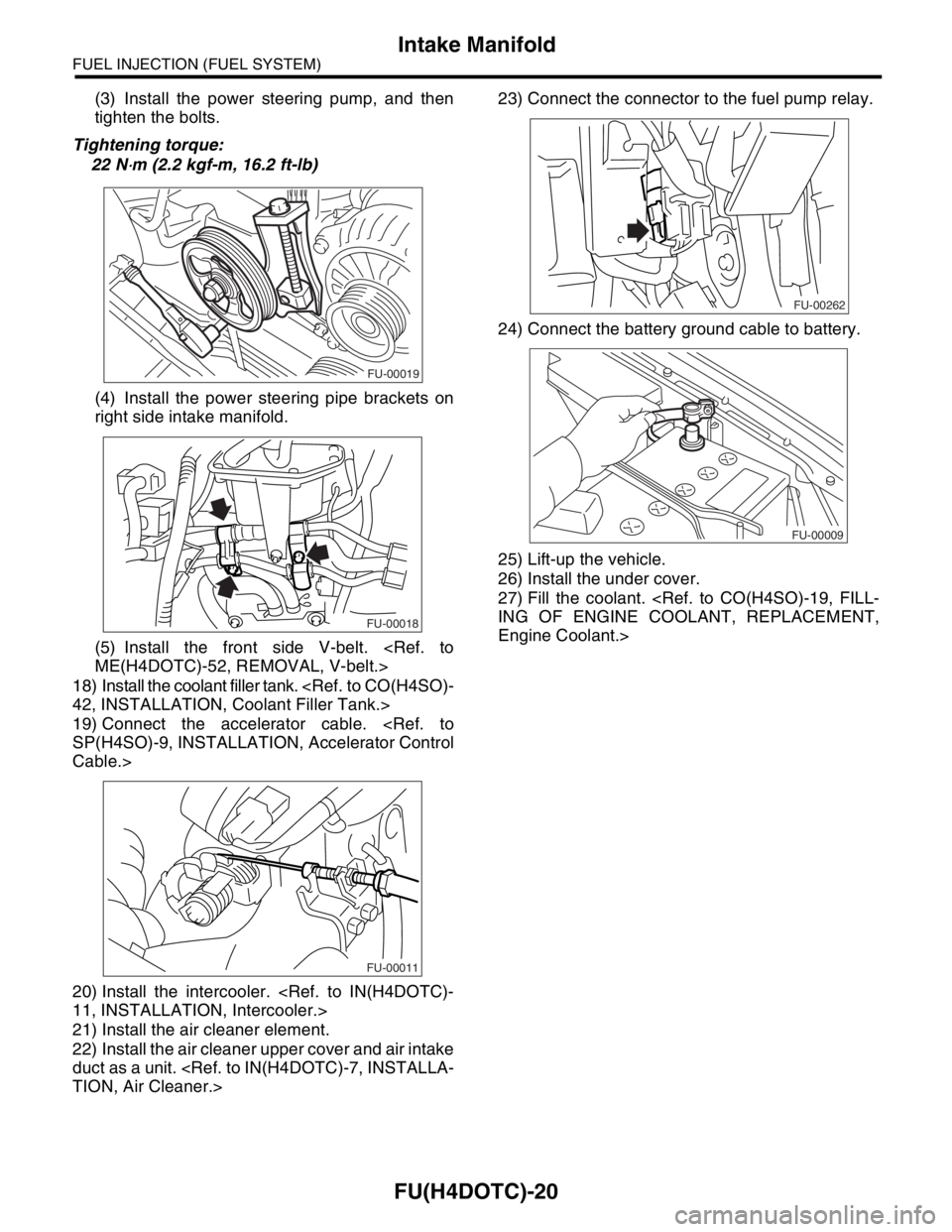
(3) Install the power steering pump, and then
tighten the bolts.
Tightening torque:
22 N
⋅m (2.2 kgf-m, 16.2 ft-lb)
(4) Install the power steering pipe brackets on
right side intake manifold.
(5) Install the front side V-belt.
18) Install the coolant filler tank.
19) Connect the accelerator cable.
Cable.>
20) Install the intercooler.
21) Install the air cleaner element.
22) Install the air cleaner upper cover and air intake
duct as a unit.
24) Connect the battery ground cable to battery.
25) Lift-up the vehicle.
26) Install the under cover.
27) Fill the coolant.
Engine Coolant.>
FU-00019
FU-00018
FU-00011
FU-00262
FU-00009