pcv SUBARU FORESTER 2004 Service Repair Manual
[x] Cancel search | Manufacturer: SUBARU, Model Year: 2004, Model line: FORESTER, Model: SUBARU FORESTER 2004Pages: 2870, PDF Size: 38.67 MB
Page 786 of 2870
FU(H4SO)-4
FUEL INJECTION (FUEL SYSTEM)
General Description
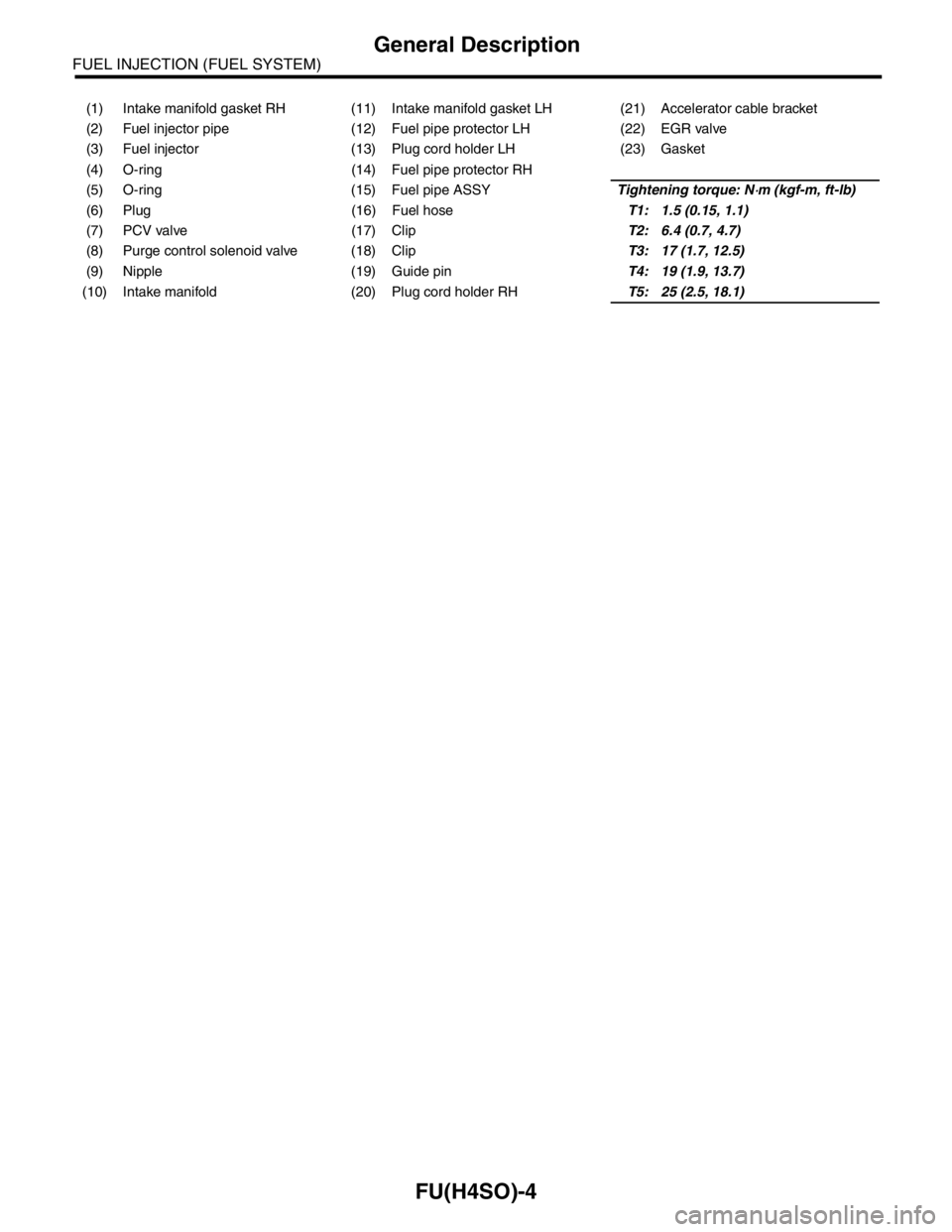
(1) Intake manifold gasket RH (11) Intake manifold gasket LH (21) Accelerator cable bracket
(2) Fuel injector pipe (12) Fuel pipe protector LH (22) EGR valve
(3) Fuel injector (13) Plug cord holder LH (23) Gasket
(4) O-ring (14) Fuel pipe protector RH
(5) O-ring (15) Fuel pipe ASSYTightening torque: N
⋅m (kgf-m, ft-lb)
(6) Plug (16) Fuel hoseT1: 1.5 (0.15, 1.1)
(7) PCV valve (17) ClipT2: 6.4 (0.7, 4.7)
(8) Purge control solenoid valve (18) ClipT3: 17 (1.7, 12.5)
(9) Nipple (19) Guide pinT4: 19 (1.9, 13.7)
(10) Intake manifold (20) Plug cord holder RHT5: 25 (2.5, 18.1)
Page 797 of 2870
FU(H4SO)-15
FUEL INJECTION (FUEL SYSTEM)
Intake Manifold
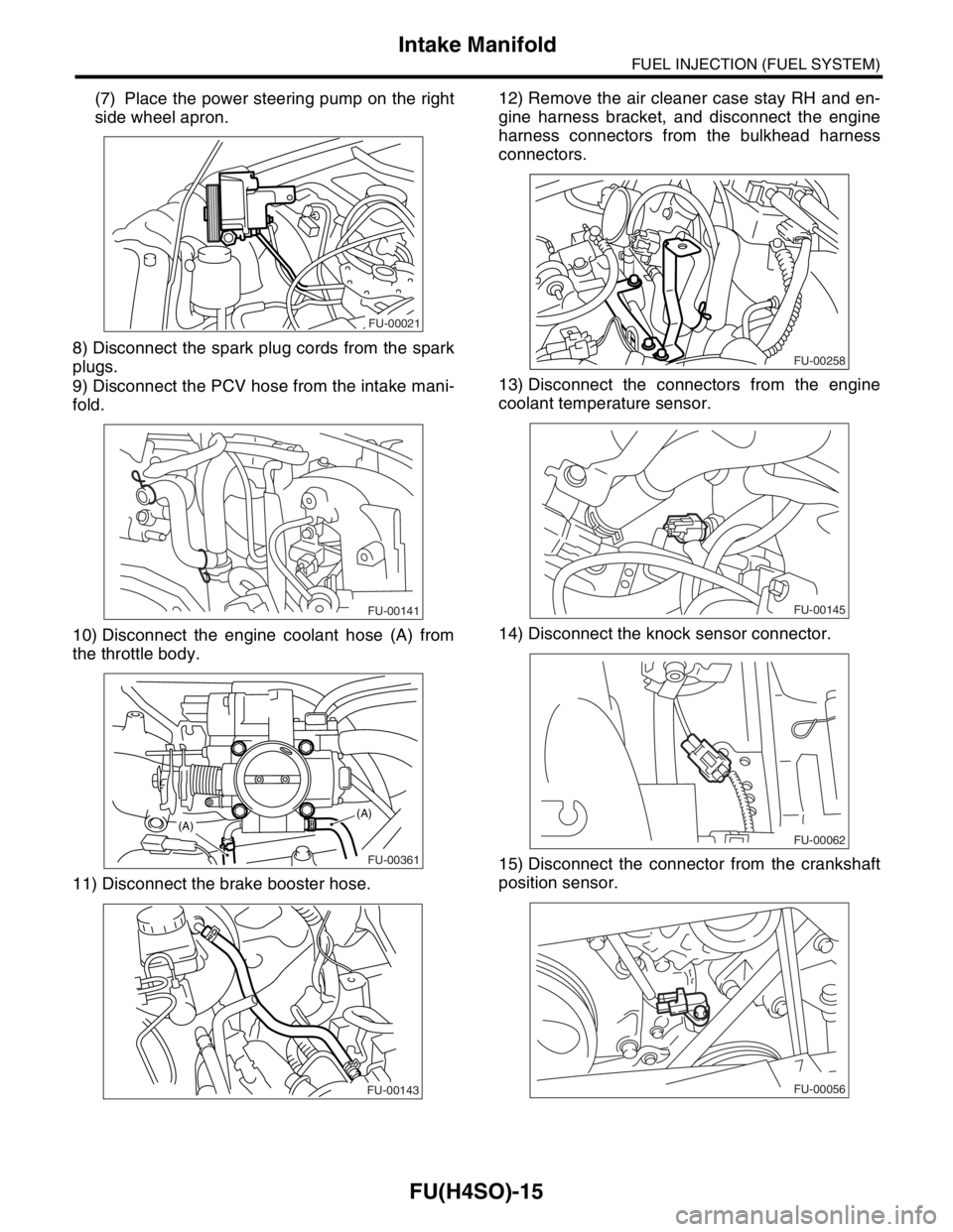
(7) Place the power steering pump on the right
side wheel apron.
8) Disconnect the spark plug cords from the spark
plugs.
9) Disconnect the PCV hose from the intake mani-
fold.
10) Disconnect the engine coolant hose (A) from
the throttle body.
11) Disconnect the brake booster hose.12) Remove the air cleaner case stay RH and en-
gine harness bracket, and disconnect the engine
harness connectors from the bulkhead harness
connectors.
13) Disconnect the connectors from the engine
coolant temperature sensor.
14) Disconnect the knock sensor connector.
15) Disconnect the connector from the crankshaft
position sensor.
FU-00021
FU-00141
FU-00361
(A)(A)
FU-00143
FU-00258
FU-00145
FU-00062
FU-00056
Page 800 of 2870
FU(H4SO)-18
FUEL INJECTION (FUEL SYSTEM)
Intake Manifold
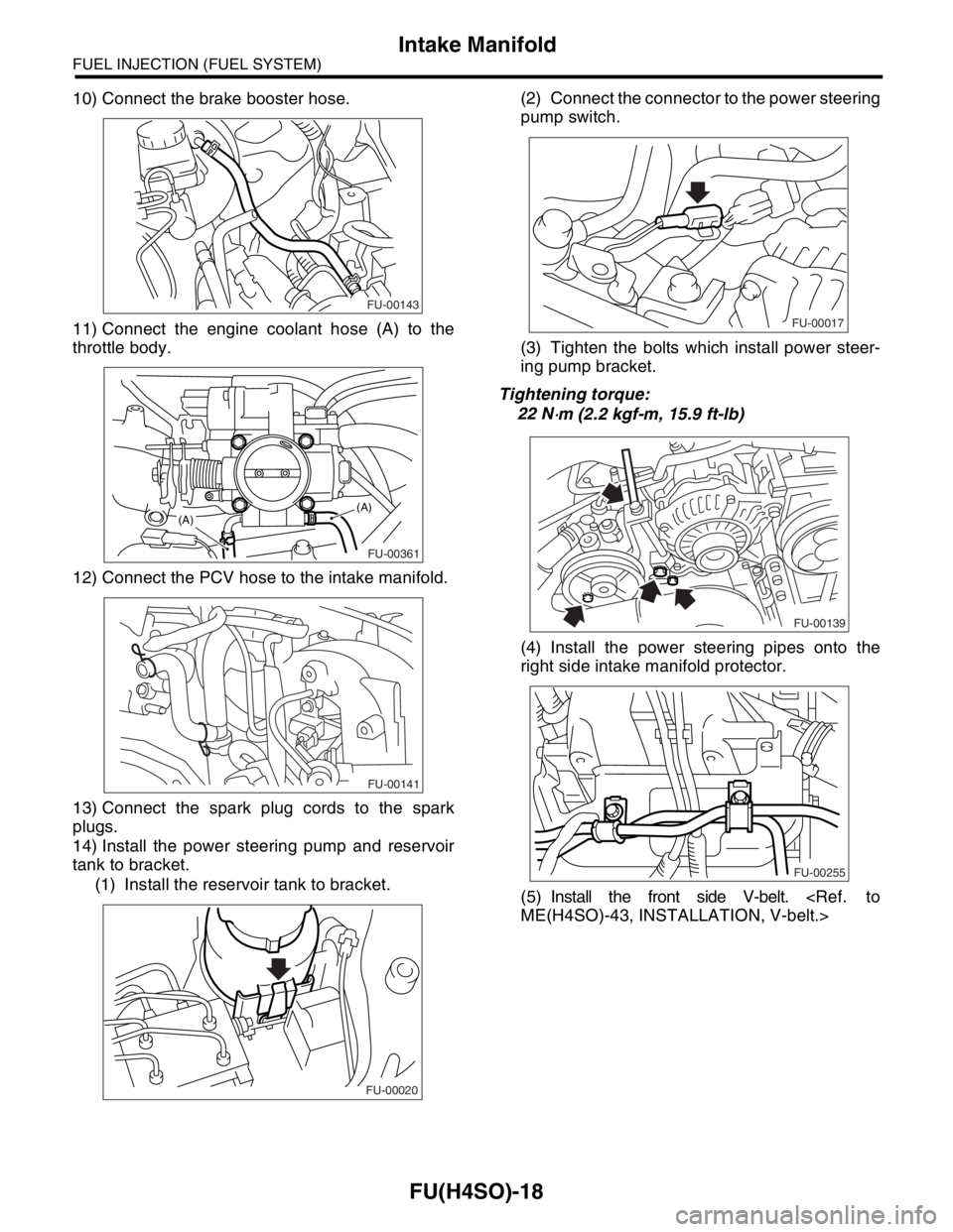
10) Connect the brake booster hose.
11) Connect the engine coolant hose (A) to the
throttle body.
12) Connect the PCV hose to the intake manifold.
13) Connect the spark plug cords to the spark
plugs.
14) Install the power steering pump and reservoir
tank to bracket.
(1) Install the reservoir tank to bracket.(2) Connect the connector to the power steering
pump switch.
(3) Tighten the bolts which install power steer-
ing pump bracket.
Tightening torque:
22 N
⋅m (2.2 kgf-m, 15.9 ft-lb)
(4) Install the power steering pipes onto the
right side intake manifold protector.
(5) Install the front side V-belt.
FU-00143
FU-00361
(A)(A)
FU-00141
FU-00020
FU-00017
FU-00139
FU-00255
Page 900 of 2870
ME(H4SO)-31
MECHANICAL
Valve Clearance
8. Valve Clearance
A: INSPECTION
NOTE:
Inspection and adjustment of the valve clearance
should be performed while engine is cold.
1) Set the vehicle on a lift.
2) Lift-up the vehicle.
3) Remove the under cover.
4) Lower the vehicle.
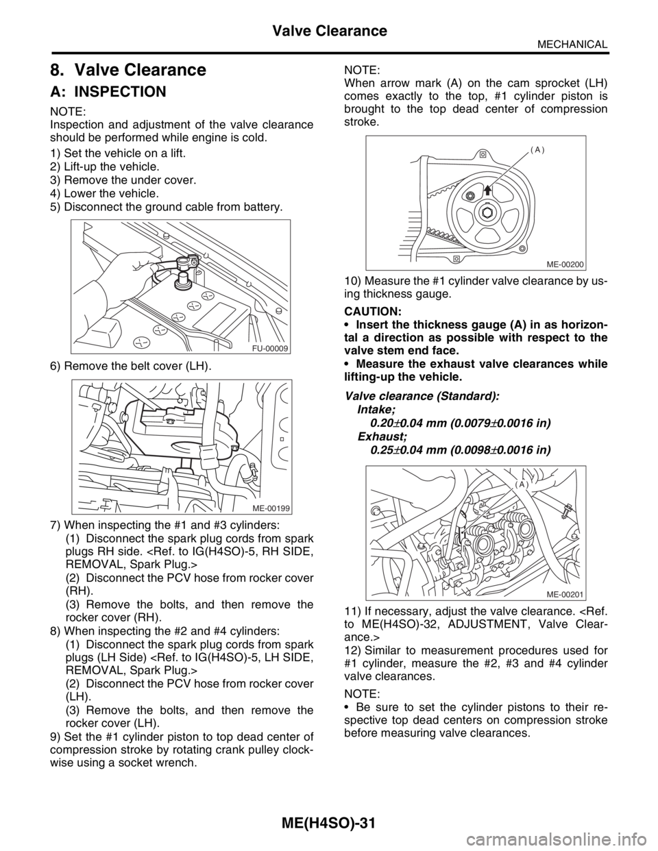
5) Disconnect the ground cable from battery.
6) Remove the belt cover (LH).
7) When inspecting the #1 and #3 cylinders:
(1) Disconnect the spark plug cords from spark
plugs RH side.
(2) Disconnect the PCV hose from rocker cover
(RH).
(3) Remove the bolts, and then remove the
rocker cover (RH).
8) When inspecting the #2 and #4 cylinders:
(1) Disconnect the spark plug cords from spark
plugs (LH Side)
(2) Disconnect the PCV hose from rocker cover
(LH).
(3) Remove the bolts, and then remove the
rocker cover (LH).
9) Set the #1 cylinder piston to top dead center of
compression stroke by rotating crank pulley clock-
wise using a socket wrench.NOTE:
When arrow mark (A) on the cam sprocket (LH)
comes exactly to the top, #1 cylinder piston is
brought to the top dead center of compression
stroke.
10) Measure the #1 cylinder valve clearance by us-
ing thickness gauge.
CAUTION:
Insert the thickness gauge (A) in as horizon-
tal a direction as possible with respect to the
valve stem end face.
Measure the exhaust valve clearances while
lifting-up the vehicle.
Valve clearance (Standard):
Intake;
0.20
±0.04 mm (0.0079±0.0016 in)
Exhaust;
0.25
±0.04 mm (0.0098±0.0016 in)
11) If necessary, adjust the valve clearance.
ance.>
12) Similar to measurement procedures used for
#1 cylinder, measure the #2, #3 and #4 cylinder
valve clearances.
NOTE:
Be sure to set the cylinder pistons to their re-
spective top dead centers on compression stroke
before measuring valve clearances.
FU-00009
ME-00199
ME-00200
(A)
ME-00201
(A)
Page 927 of 2870
ME(H4SO)-56
MECHANICAL
Valve Rocker Assembly
18.Valve Rocker Assembly
A: REMOVAL
1) Remove the V-belt.
2) Remove the crank pulley.
3) Remove the belt cover.
4) Remove the timing belt assembly.
5) Remove the cam sprocket.
6) Disconnect the PCV hose and remove rocker
cover.
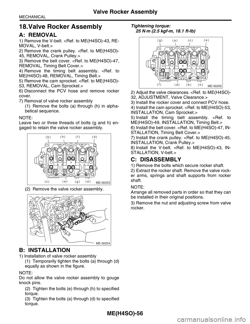
7) Removal of valve rocker assembly
(1) Remove the bolts (a) through (h) in alpha-
betical sequence.
NOTE:
Leave two or three threads of bolts (g and h) en-
gaged to retain the valve rocker assembly.
(2) Remove the valve rocker assembly.
B: INSTALLATION
1) Installation of valve rocker assembly
(1) Temporarily tighten the bolts (a) through (d)
equally as shown in the figure.
NOTE:
Do not allow the valve rocker assembly to gouge
knock pins.
(2) Tighten the bolts (e) through (h) to specified
torque.
(3) Tighten the bolts (a) through (d) to specified
torque.Tightening torque:
25 N
⋅m (2.5 kgf-m, 18.1 ft-lb)
2) Adjust the valve clearances.
3) Install the rocker cover and connect PCV hose.
4) Install the cam sprocket.
5) Install the timing belt assembly.
6) Install the belt cover.
7) Install the crank pulley.
8) Install the V-belt.
C: DISASSEMBLY
1) Remove the bolts which secure rocker shaft.
2) Extract the rocker shaft. Remove the valve rock-
er arms, springs and shaft supports from rocker
shaft.
NOTE:
Arrange all removed parts in order so that they can
be installed in their original positions.
3) Remove the nut and adjusting screw from valve
rocker.
ME-00253(a) (b)
(c)(d)
(e)(f)
(g) (h)
ME-00254
ME-00255
(a)
(b)(c)
(d)(e)
(f)(g)
(h)
Page 931 of 2870
ME(H4SO)-60
MECHANICAL
Camshaft
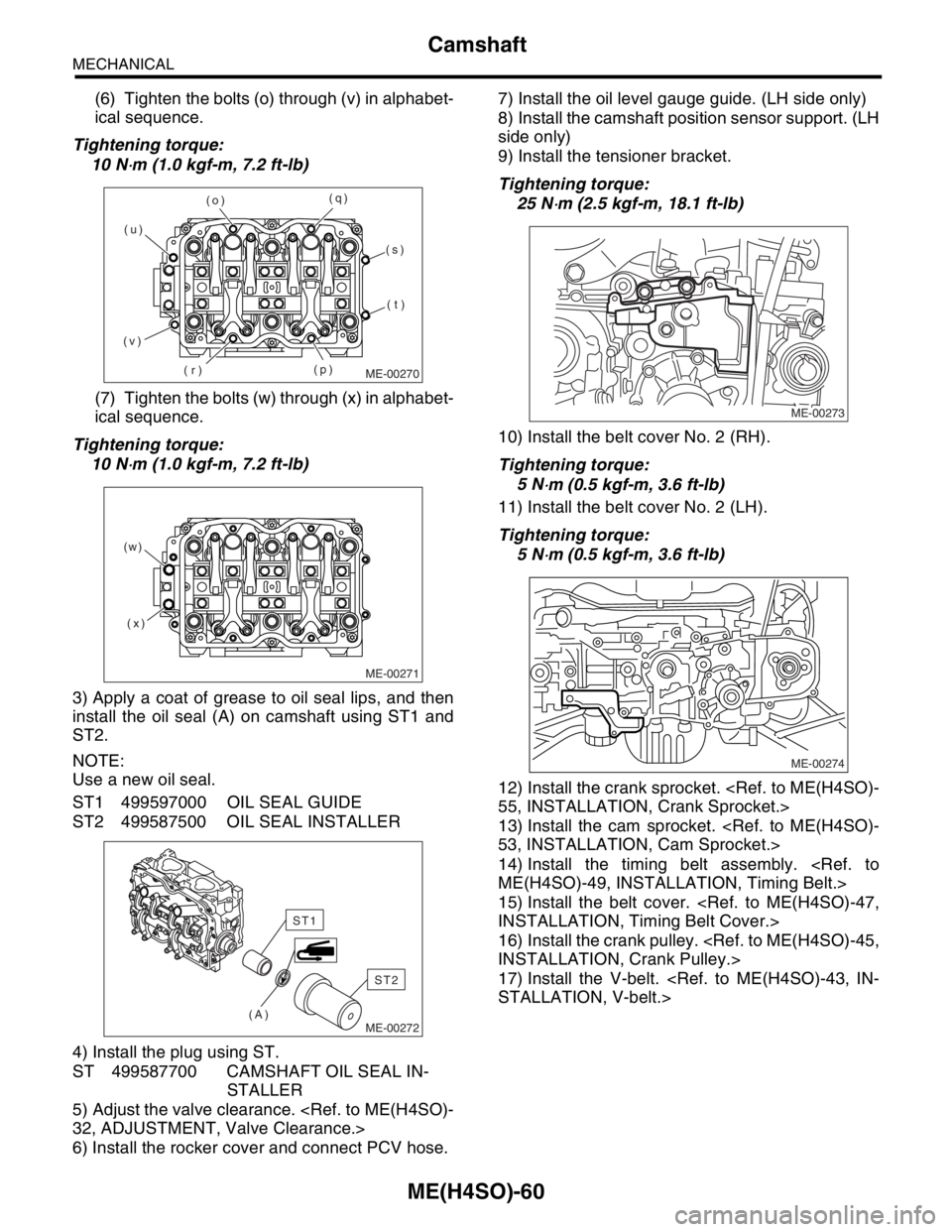
(6) Tighten the bolts (o) through (v) in alphabet-
ical sequence.
Tightening torque:
10 N
⋅m (1.0 kgf-m, 7.2 ft-lb)
(7) Tighten the bolts (w) through (x) in alphabet-
ical sequence.
Tightening torque:
10 N
⋅m (1.0 kgf-m, 7.2 ft-lb)
3) Apply a coat of grease to oil seal lips, and then
install the oil seal (A) on camshaft using ST1 and
ST2.
NOTE:
Use a new oil seal.
ST1 499597000 OIL SEAL GUIDE
ST2 499587500 OIL SEAL INSTALLER
4) Install the plug using ST.
ST 499587700 CAMSHAFT OIL SEAL IN-
STALLER
5) Adjust the valve clearance.
6) Install the rocker cover and connect PCV hose.7) Install the oil level gauge guide. (LH side only)
8) Install the camshaft position sensor support. (LH
side only)
9) Install the tensioner bracket.
Tightening torque:
25 N
⋅m (2.5 kgf-m, 18.1 ft-lb)
10) Install the belt cover No. 2 (RH).
Tightening torque:
5 N
⋅m (0.5 kgf-m, 3.6 ft-lb)
11) Install the belt cover No. 2 (LH).
Tightening torque:
5 N
⋅m (0.5 kgf-m, 3.6 ft-lb)
12) Install the crank sprocket.
13) Install the cam sprocket.
14) Install the timing belt assembly.
15) Install the belt cover.
16) Install the crank pulley.
17) Install the V-belt.
ME-00270
(o)
(r)(q)
(v)(u)
(p)(s)
(t)
ME-00271
(x) (w)
ME-00272(A)
ST2
ST1
ME-00273
ME-00274
Page 963 of 2870
ME(H4SO)-92
MECHANICAL
Engine Trouble in General
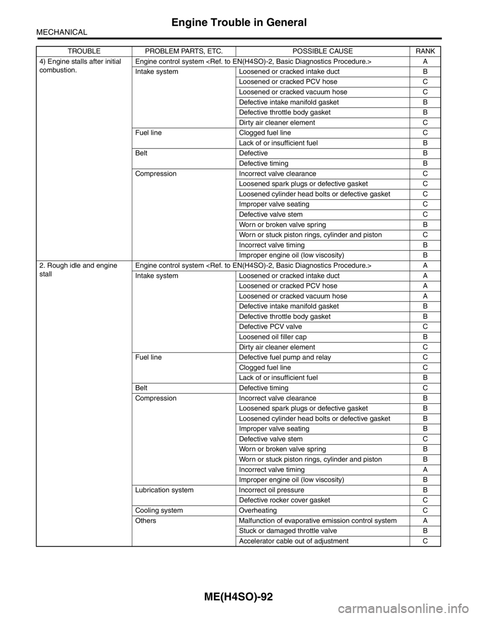
4) Engine stalls after initial
combustion. Engine control system
Intake system Loosened or cracked intake duct B
Loosened or cracked PCV hose C
Loosened or cracked vacuum hose C
Defective intake manifold gasket B
Defective throttle body gasket B
Dirty air cleaner element C
Fuel line Clogged fuel line C
Lack of or insufficient fuel B
Belt Defective B
Defective timing B
Compression Incorrect valve clearance C
Loosened spark plugs or defective gasket C
Loosened cylinder head bolts or defective gasket C
Improper valve seating C
Defective valve stem C
Worn or broken valve spring B
Worn or stuck piston rings, cylinder and piston C
Incorrect valve timing B
Improper engine oil (low viscosity) B
2. Rough idle and engine
stallEngine control system
Intake system Loosened or cracked intake duct A
Loosened or cracked PCV hose A
Loosened or cracked vacuum hose A
Defective intake manifold gasket B
Defective throttle body gasket B
Defective PCV valve C
Loosened oil filler cap B
Dirty air cleaner element C
Fuel line Defective fuel pump and relay C
Clogged fuel line C
Lack of or insufficient fuel B
Belt Defective timing C
Compression Incorrect valve clearance B
Loosened spark plugs or defective gasket B
Loosened cylinder head bolts or defective gasket B
Improper valve seating B
Defective valve stem C
Worn or broken valve spring B
Worn or stuck piston rings, cylinder and piston B
Incorrect valve timing A
Improper engine oil (low viscosity) B
Lubrication system Incorrect oil pressure B
Defective rocker cover gasket C
Cooling system Overheating C
Others Malfunction of evaporative emission control system A
Stuck or damaged throttle valve B
Accelerator cable out of adjustment C TROUBLE PROBLEM PARTS, ETC. POSSIBLE CAUSE RANK
Page 964 of 2870
ME(H4SO)-93
MECHANICAL
Engine Trouble in General
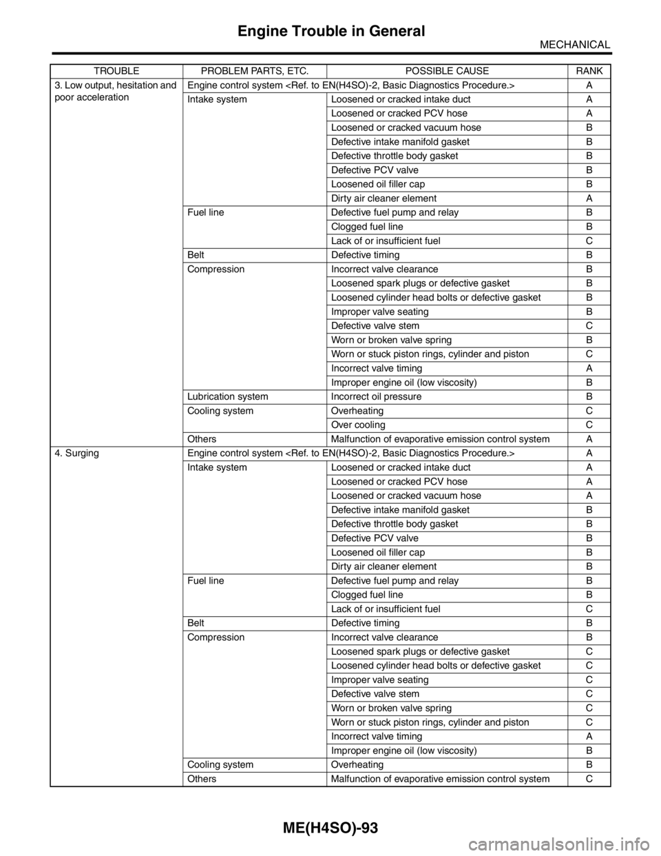
3. Low output, hesitation and
poor accelerationEngine control system
Intake system Loosened or cracked intake duct A
Loosened or cracked PCV hose A
Loosened or cracked vacuum hose B
Defective intake manifold gasket B
Defective throttle body gasket B
Defective PCV valve B
Loosened oil filler cap B
Dirty air cleaner element A
Fuel line Defective fuel pump and relay B
Clogged fuel line B
Lack of or insufficient fuel C
Belt Defective timing B
Compression Incorrect valve clearance B
Loosened spark plugs or defective gasket B
Loosened cylinder head bolts or defective gasket B
Improper valve seating B
Defective valve stem C
Worn or broken valve spring B
Worn or stuck piston rings, cylinder and piston C
Incorrect valve timing A
Improper engine oil (low viscosity) B
Lubrication system Incorrect oil pressure B
Cooling system Overheating C
Over cooling C
Others Malfunction of evaporative emission control system A
4. Surging Engine control system
Intake system Loosened or cracked intake duct A
Loosened or cracked PCV hose A
Loosened or cracked vacuum hose A
Defective intake manifold gasket B
Defective throttle body gasket B
Defective PCV valve B
Loosened oil filler cap B
Dirty air cleaner element B
Fuel line Defective fuel pump and relay B
Clogged fuel line B
Lack of or insufficient fuel C
Belt Defective timing B
Compression Incorrect valve clearance B
Loosened spark plugs or defective gasket C
Loosened cylinder head bolts or defective gasket C
Improper valve seating C
Defective valve stem C
Worn or broken valve spring C
Worn or stuck piston rings, cylinder and piston C
Incorrect valve timing A
Improper engine oil (low viscosity) B
Cooling system Overheating B
Others Malfunction of evaporative emission control system C TROUBLE PROBLEM PARTS, ETC. POSSIBLE CAUSE RANK
Page 965 of 2870
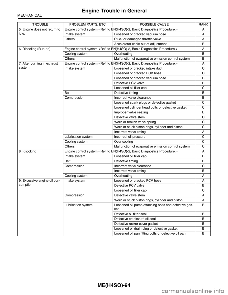
ME(H4SO)-94
MECHANICAL
Engine Trouble in General
5. Engine does not return to
idle.Engine control system
Intake system Loosened or cracked vacuum hose A
Others Stuck or damaged throttle valve A
Accelerator cable out of adjustment B
6. Dieseling (Run-on) Engine control system
Cooling system Overheating B
Others Malfunction of evaporative emission control system B
7. After burning in exhaust
systemEngine control system
Intake system Loosened or cracked intake duct C
Loosened or cracked PCV hose C
Loosened or cracked vacuum hose B
Defective PCV valve B
Loosened oil filler cap C
Belt Defective timing B
Compression Incorrect valve clearance B
Loosened spark plugs or defective gasket C
Loosened cylinder head bolts or defective gasket C
Improper valve seating B
Defective valve stem C
Worn or broken valve spring C
Worn or stuck piston rings, cylinder and piston C
Incorrect valve timing A
Lubrication system Incorrect oil pressure C
Cooling system Over cooling C
Others Malfunction of evaporative emission control system C
8. Knocking Engine control system
Intake system Loosened oil filler cap B
Belt Defective timing B
Compression Incorrect valve clearance C
Incorrect valve timing B
Cooling system Overheating A
9. Excessive engine oil con-
sumptionIntake system Loosened or cracked PCV hose A
Defective PCV valve B
Loosened oil filler cap C
Compression Defective valve stem A
Worn or stuck piston rings, cylinder and piston A
Lubrication system Loosened oil pump attaching bolts and defective gas-
ketB
Defective oil filter seal B
Defective crankshaft oil seal B
Defective rocker cover gasket B
Loosened oil drain plug or defective gasket B
Loosened oil pan fitting bolts or defective oil pan B TROUBLE PROBLEM PARTS, ETC. POSSIBLE CAUSE RANK
Page 1144 of 2870
EN(H4SO)-46
ENGINE (DIAGNOSTIC)
Compulsory Valve Operation Check Mode
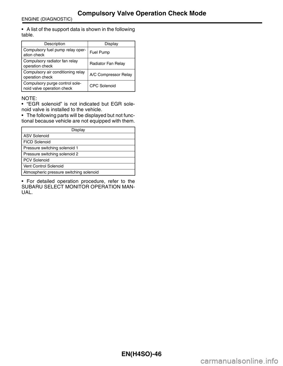
A list of the support data is shown in the following
table.
NOTE:
“EGR solenoid” is not indicated but EGR sole-
noid valve is installed to the vehicle.
The following parts will be displayed but not func-
tional because vehicle are not equipped with them.
For detailed operation procedure, refer to the
SUBARU SELECT MONITOR OPERATION MAN-
UAL.
Description Display
Compulsory fuel pump relay oper-
ation checkFuel Pump
Compulsory radiator fan relay
operation checkRadiator Fan Relay
Compulsory air conditioning relay
operation checkA/C Compressor Relay
Compulsory purge control sole-
noid valve operation checkCPC Solenoid
Display
ASV Solenoid
FICD Solenoid
Pressure switching solenoid 1
Pressure switching solenoid 2
PCV Solenoid
Vent Control Solenoid
Atmospheric pressure switching solenoid