power steering SUBARU FORESTER 2004 Service Repair Manual
[x] Cancel search | Manufacturer: SUBARU, Model Year: 2004, Model line: FORESTER, Model: SUBARU FORESTER 2004Pages: 2870, PDF Size: 38.67 MB
Page 182 of 2870

AB-50
AIRBAG SYSTEM (DIAGNOSTIC)
Diagnostic Procedure with Diagnostic Trouble Code (DTC)
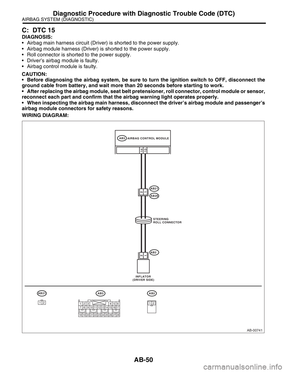
C: DTC 15
DIAGNOSIS:
Airbag main harness circuit (Driver) is shorted to the power supply.
Airbag module harness (Driver) is shorted to the power supply.
Roll connector is shorted to the power supply.
Driver’s airbag module is faulty.
Airbag control module is faulty.
CAUTION:
Before diagnosing the airbag system, be sure to turn the ignition switch to OFF, disconnect the
ground cable from battery, and wait more than 20 seconds before starting to work.
After replacing the airbag module, seat belt pretensioner, roll connector, control module or sensor,
reconnect each part and confirm that the airbag warning light operates properly.
When inspecting the airbag main harness, disconnect the driver’s airbag module and passenger’s
airbag module connectors for safety reasons.
WIRING DIAGRAM:
AB-00741
AB3
AB21
AB26
AB222
11
14
13
AB21AB3AB2
1212
AIRBAG CONTROL MODULE
STEERING
ROLL CONNECTOR
INFLATOR
(DRIVER SIDE)
1234567891011121314151617
1819202122232425262728
Page 370 of 2870

BS-4
BODY STRUCTURE
Datum Points
(1) Radiator panel gauge hole 6 mm
(0.24 in) dia. (Vehicle center)(14) Fender attaching hole 10 mm
(0.39 in) dia. (Symmetrical)(31) Harness attaching hole 7 mm
(0.28 in) dia. (Symmetrical)
(2) Radiator attaching hole 12 mm
(0.47 in) dia.(15) Fender attaching hole 10 mm
(0.39 in) dia. (Symmetrical)(32) Trim attaching hole 8.5 mm (0.33
in) dia. (Symmetrical)
(3) Headlight attaching hole 7 mm
(0.28 in) dia. (Symmetrical)(16) Front door hinge attaching hole 12
mm (0.47 in) dia. (Symmetrical)(33) Trim attaching hole 7 mm (0.28 in)
dia. (Symmetrical)
(4) Frame plate gauge hole 8 mm
(0.31 in) dia. (Symmetrical)(17) Front door hinge attaching hole 12
mm (0.47 in) dia. (Symmetrical)(34) Harness attaching hole 7×7 mm
(0.28×0.28 in) (Symmetrical)
(5) Bumper beam attaching hole 11
mm (0.43 in) dia. (Symmetrical)(20) Front door switch attaching hole
4.1 mm (0.16 in) dia. (Symmetri-
cal)(35) Tonneau cover bracket attaching
hole 5.5 mm (0.22 in) dia. (Sym-
metrical)
(6) Fender attaching hole 7 mm (0.28
in) dia. (Symmetrical)
(21) Rear door hinge attaching hole 12
mm (0.47 in) dia. (Symmetrical)(36) Rear strut attaching hole 10 mm
(0.39 in) (Symmetrical)
(7) Fender attaching hole 9 mm (0.35
in) dia. (Symmetrical)
(22) Rear door hinge attaching hole 12
mm (0.47 in) dia. (Symmetrical)(37) Floor mat attaching hole 8 mm
(0.31 in) dia.
(8) Power steering tank attaching hole
RH ATF cooler pipe attaching hole
LH 9 mm (0.35 in) dia.(23) Front weather strip attaching hole
5.2 mm (0.20 in) dia. (Symmetri-
cal)(38) Trim attaching hole 9×9 mm
(0.35×0.35 in) (Symmetrical)
(9) Fender attaching hole 10 mm
(0.39 in) dia. (Symmetrical)(39) Trim attaching hole 8 mm (0.31 in)
dia. (Symmetrical)
(25) Rear weather strip attaching hole
5.2 mm (0.20 in) dia. (Symmetri-
cal) (10) Fender attaching hole 7 mm (0.28
in) dia. (Symmetrical)(40) Trim attaching hole 8 mm (0.31 in)
dia. (Symmetrical)
(11) Modular bracket gauge hole 8 mm
(0.31 in) dia. (Vehicle center)(26) Rear door switch attaching hole
4.1 mm (0.16 in) dia. (Symmetri-
cal)
(12) Front strut attaching hole 9.5 mm
(0.37 in) dia. (Symmetrical)
(29) Trim attaching hole 8.5 mm (0.33
in) dia. (Symmetrical)
(13) Front glass attaching hole LH
6.5×10.5 mm (0.26×0.41 in) RH
6.5×7 mm (0.26×0.28 in)(30) Pad attaching hole 5 mm (0.20 in)
dia. (Symmetrical)
Page 665 of 2870

FUJI HEAVY INDUSTRIES LTD. G8080GE6
2004 FORESTER SERVICE MANUAL QUICK REFERENCE INDEX
CHASSIS SECTION
This service manual has been prepared
to provide SUBARU service personnel
with the necessary information and data
for the correct maintenance and repair
of SUBARU vehicles.
This manual includes the procedures
for maintenance, disassembling, reas-
sembling, inspection and adjustment of
components and diagnostics for guid-
ance of experienced mechanics.
Please peruse and utilize this manual
fully to ensure complete repair work for
satisfying our customers by keeping
their vehicle in optimum condition.
When replacement of parts during
repair work is needed, be sure to use
SUBARU genuine parts.
All information, illustration and specifi-
cations contained in this manual are
based on the latest product information
available at the time of publication
approval.FRONT SUSPENSION FS
REAR SUSPENSION RS
WHEEL AND TIRE SYSTEM WT
DIFFERENTIAL DI
TRANSFER CASE TC
DRIVE SHAFT SYSTEM DS
ABS ABS
ABS (DIAGNOSTIC) ABS
BRAKE BR
PARKING BRAKE PB
POWER ASSISTED SYSTEM
(POWER STEERING)PS
Page 693 of 2870

SPC-4
SPECIFICATION
Forester
F: SUSPENSION
G: BRAKE
★: RHD model
H: TIRE
I: CAPACITY
★1: With oil pump★2: MT model with oil cooler Included★3: Model with ATF warmer Front Macpherson strut type, Independent, Coil spring
Rear Dual-link type, Independent, Coil spring
Model 2.0 L Non-turbo, 2.5 L Non-turbo
2.0 L Turbo, 2.5 L Non-turbo
★, 2.5 L Non-turbo
Service brake system Dual circuit hydraulic with vacuum suspended power unit
Front Ventilated disc brake
Rear Drum brake Disc brake
Parking brake Mechanical on rear brakes
Rim size 15×6J 16×6 1/2J
Tire size 205/70 R15 95H 215/60 R16 95V, P215/60 R16 94H
Type Steel belted radial, Tubeless
Model 2.0 L Non-turbo 2.0 L Turbo 2.5 L Non-turbo 2.5 L Turbo
Tr a n s m i s s i o n 5 M T 4 AT 5 M T 4 AT 5 M T 4 AT 5 M T 4 AT
Fuel tank2 (US gal, Imp gal) 60 (15.9, 13.2)
Engine oil
(When
replacing)2 (US qt, Imp qt) Approx. 4.0 (4.2, 3.5)
Tr a n s m i s -
sion gear oil2 (US qt, Imp qt)4.0
(4.2, 3.5)—3.5
(3.7, 3.1),
3.9
(4.1, 3.4)
★1
—4.0
(4.2, 3.5)—3.5
(3.7, 3.1)—
AT F2 (US qt, Imp qt) —8.4
(8.9, 7.4)—9.3
(9.8, 8.2)—9.3
(9.8, 8.2)—9.3
(9.8, 8.2)
Front differ-
ential gear
oil2 (US qt, Imp qt) —1.2
(1.3, 1.1)—1.2
(1.3, 1.1)—1.2
(1.3, 1.1)—1.2
(1.3, 1.1)
Rear differ-
ential gear
oil2 (US qt, Imp qt) 0.8 (0.8, 0.6)
Pow er
steering
fluid2 (US qt, Imp qt) 0.7 (0.7, 0.6)
Engine
coolant2 (US qt, Imp qt)6.6
(7.0, 5.8)6.5
(6.9, 5.7),
6.9
(7.3, 6.1)
★3
7.4
(7.8, 6.5)7.3
(7.7, 6.4)
★2
6.9
(7.3, 6.1)6.8
(7.2, 6.0)7.4
(7.8, 6.5)7.3
(7.7, 6.4)
Page 720 of 2870

RM-5
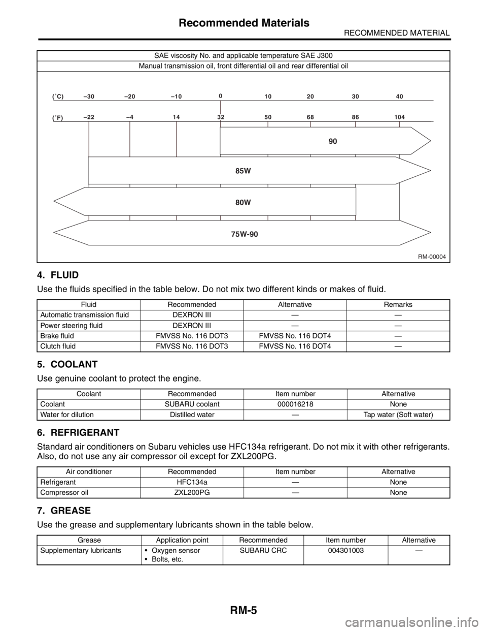
RECOMMENDED MATERIAL
Recommended Materials
4. FLUID
Use the fluids specified in the table below. Do not mix two different kinds or makes of fluid.
5. COOLANT
Use genuine coolant to protect the engine.
6. REFRIGERANT
Standard air conditioners on Subaru vehicles use HFC134a refrigerant. Do not mix it with other refrigerants.
Also, do not use any air compressor oil except for ZXL200PG.
7. GREASE
Use the grease and supplementary lubricants shown in the table below.
SAE viscosity No. and applicable temperature SAE J300
Manual transmission oil, front differential oil and rear differential oil
Fluid Recommended Alternative Remarks
Automatic transmission fluid DEXRON III — —
Power steering fluid DEXRON III — —
Brake fluid FMVSS No. 116 DOT3 FMVSS No. 116 DOT4 —
Clutch fluid FMVSS No. 116 DOT3 FMVSS No. 116 DOT4 —
Coolant Recommended Item number Alternative
Coolant SUBARU coolant 000016218 None
Water for dilution Distilled water — Tap water (Soft water)
Air conditioner Recommended Item number Alternative
Refrigerant HFC134a — None
Compressor oil ZXL200PG — None
Grease Application point Recommended Item number Alternative
Supplementary lubricants Oxygen sensor
Bolts, etc.SUBARU CRC 004301003 —
RM-00004 (�F)–22 –4 14 50 68 86 104 (�C)–30 –20 –100
10 20 30 40
85W
75W-9080W90
32
Page 727 of 2870

PI-4
PRE-DELIVERY INSPECTION
Pre-delivery Inspection
Checks with the Engine Running
Dynamic Test with the Vehicle Running
Checks after Dynamic Test
Step Check point
26. Test mode connectors Test mode connectors
27. Starting condition Start the engine and check that the engine starts smoothly.
28. Exhaust system Check that the exhaust noise is normal and no leaks are found.
29. Indicator light Check that all the indicator lights operate normally.
30. Clock Check that the clock operates normally.
31. Radio Check that the radio system operates normally.
32. Front accessory power supply socket Check that the front accessory power supply socket operates normally.
33. Lighting system Check that the lighting systems operate normally.
34. Window washer Check that the window washer system operates normally.
35. Wiper Check that the wiper system operates normally.
36. Power window operation check Check the power window for correct operations.
Step Check point
37. Brake test Check that the foot brake operates normally.
38. Parking brake Check that the parking brake operates normally.
39. AT shift control Check the AT shift patterns are correct.
40. Heater & ventilation Check that the heater & ventilation system operates normally.
41. Air conditioner Check that the air conditioner operates normally.
42. Speed control Check that the speed control operates normally.
Step Check point
43. ATF level Check that the ATF level is normal.
44. Power steering fluid level Check that the power steering fluid level is normal.
45. Fluid leak check Check for fluid/oil leaks.
46. Water leak check Spray the vehicle with water and check for water leaks.
47. Appearance check 2 (1) Remove the protective coating (wrap guard).(if any)
(2) Check the body paints for damage and smears.
(3) Check the plated parts for damage and rust.
Page 735 of 2870

PI-12
PRE-DELIVERY INSPECTION
Pre-delivery Inspection
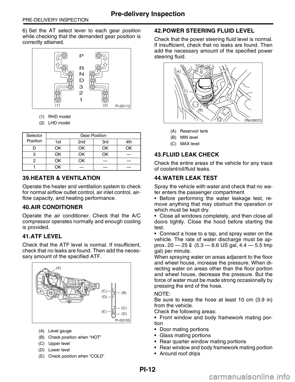
6) Set the AT select lever to each gear position
while checking that the demanded gear position is
correctly attained.
39.HEATER & VENTILATION
Operate the heater and ventilation system to check
for normal airflow outlet control, air inlet control, air-
flow capacity, and heating performance.
40.AIR CONDITIONER
Operate the air conditioner. Check that the A/C
compressor operates normally and enough cooling
is provided.
41.ATF LEVEL
Check that the ATF level is normal. If insufficient,
check that no leaks are found. Then add the neces-
sary amount of the specified ATF.
42.POWER STEERING FLUID LEVEL
Check that the power steering fluid level is normal.
If insufficient, check that no leaks are found. Then
add the necessary amount of the specified power
steering fluid.
43.FLUID LEAK CHECK
Check the entire areas of the vehicle for any trace
of coolant/oil/fluid leaks.
44.WATER LEAK TEST
Spray the vehicle with water and check that no wa-
ter enters the passenger compartment.
Before performing the water leakage test, re-
move anything that may obstruct the operation or
which must be kept dry.
Close all windows completely, and then close all
doors tightly. Close the hood before starting the
test.
Connect a hose to a tap, and spray water on the
vehicle. The rate of water discharge must be ap-
prox. 20 — 252 (5.3 — 6.6 US gal, 4.4 — 5.5 Imp
gal) per minute.
When spraying water on areas adjacent to the floor
and wheel house, increase the pressure. When di-
recting water on areas other than the floor portion
and wheel house, decrease the pressure. But the
force of water must be made strong occasionally by
pressing the end of the hose.
NOTE:
Be sure to keep the hose at least 10 cm (3.9 in)
from the vehicle.
Check the following areas:
Front window and body framework mating por-
tion
Door mating portions
Glass mating portions
Rear quarter window mating portions
Rear window and body framework mating portion
Around roof drips
(1) RHD model
(2) LHD model
Selector
Po si t io nGear Position
1st 2nd 3rd 4th
D OKOKOKOK
3 OKOKOK —
2OKOK——
1OK———
(A) Level gauge
(B) Check position when “HOT”
(C) Upper level
(D) Lower level
(E) Check position when “COLD”
PI-00112(1) (2)
P
R
N
D
3
2
1
PI-00105
COLD
LFHOT LF
(A)
(C)
(D)
(C)
(D)
(E)
(B)
(A) Reservoir tank
(B) MIN level
(C) MAX level
PM-00070
(A)
(C)
(B)
Page 738 of 2870

PERIODIC MAINTENANCE SERVICE
PM
Page
1. General Description ....................................................................................2
2. Schedule .....................................................................................................3
3. Engine Oil....................................................................................................7
4. Engine Oil Filter...........................................................................................9
5. Spark Plugs ...............................................................................................10
6. V-belt .........................................................................................................11
7. Timing Belt ................................................................................................13
8. Fuel Line ...................................................................................................17
9. Fuel Filter ..................................................................................................18
10. Air Cleaner Element ..................................................................................19
11. Cooling System .........................................................................................20
12. Engine Coolant..........................................................................................21
13. Clutch System ...........................................................................................23
14. Transmission Gear Oil ..............................................................................24
15. Hill-holder System .....................................................................................25
16. ATF ...........................................................................................................26
17. Front & Rear Differential Oil ......................................................................28
18. Brake Line .................................................................................................30
19. Brake Fluid ................................................................................................32
20. Disc Brake Pads and Discs .......................................................................33
21. Brake Linings and Drums ..........................................................................34
22. Suspension ...............................................................................................36
23. Wheel Bearing...........................................................................................38
24. Axle Boots & Joints ...................................................................................39
25. Tire Rotation..............................................................................................40
26. Steering System (Power Steering) ............................................................41
Page 741 of 2870

PM-4
PERIODIC MAINTENANCE SERVICE
Schedule
2. EXCEPT FOR EUROPE AREA
For periodic maintenance of over 50,000 km (30,000 miles) or 48 months, carry out inspections by referring
to the following tables. For a maintenance period gone beyond these tables, apply them repeatedly as a set
of 50,000 km (30,000 miles) or 48 months.
For periodic maintenance of over 100,000 km (60,000 miles) or 48 months, carry out inspections by referring
to the following tables. For a maintenance period gone beyond these tables, apply them repeatedly as a set
of 100,000 km (60,000 miles) or 48 months.
Symbols used:
R: Replace
I: Inspection
(I): Recommended service for safe vehicle operation.
N
OTE:
(1) When the vehicle is used in extremely dusty conditions, the air cleaner element should be replaced more often.
(2) ATF filter is a maintenance free part. ATF filter needs replacement, when it is physically damaged or ATF leaked.Maintenance Interval
[Number of months or km (miles), whichever occurs first]
Months 12 24 36 48
Remarks ×1,000 km 5 12.5 25 37.5 50
×1,000 miles 3 7.5 15 22.5 30
1 Engine oil R R R R
2 Engine oil filter R R R R
Maintenance Interval
[Number of months or km (miles), whichever occurs first]
Months 12 24 36 48
Remarks ×1,000 km 1.6 25 50 75 100
×1,000 miles 1 15 30 45 60
3 Spark plugs For Turbo R
Others R R R R
4Drive belt(s) IIII
5 Camshaft drive belt R
6 Fuel line I I
7 Fuel filter R R
8 Air cleaner element I R I R
9 Cooling system I I
10 Coolant R R
11 Clutch system I I I I I
12 Hill-holder system I I I I I
13 Transmission oil R R
14 ATF R R
15 Front & rear differential oil R R
16 Brake line I I
17 Brake fluid R R
18 Disc brake pads & discs I I I I
19 Brake linings and drums I I
20 Parking brake I I I I
21 Suspension I I I I
22 Wheel bearing (I)
23 Axle boots & joints I I I I
24 Steering system (Power steering) I I I I
Page 742 of 2870

PM-5
PERIODIC MAINTENANCE SERVICE
Schedule
B: MAINTENANCE SCHEDULE 2
1. EUROPE AREA
Item EveryRepeat short
distance driveRepeat
rough/muddy
road driveExtremely
cold weather
areaSalt or other
corrosive
used or
coastal areaHigh humid-
ity or moun-
tain areaRepeat tow-
ing trailer
Engine oil Replace
more fre-
quentlyReplace
more fre-
quentlyReplace
more fre-
quently
Engine oil filter Replace
more fre-
quentlyReplace
more fre-
quentlyReplace
more fre-
quently
Fuel line 12 months
I 15,000 km
9,000 miles
Transmission oilReplace
more fre-
quently
AT FReplace
more fre-
quently
Front & rear dif-
ferential oilReplace
more fre-
quently
Brake line 12 months
I 15,000 km
9,000 miles
Brake fluid 12 months
R 15,000 km
9,000 miles
Brake pads 12 months
II I I 15,000 km
9,000 miles
Brake linings
and drums12 months
II I I 15,000 km
9,000 miles
Parking brake 12 months
II I I 15,000 km
9,000 miles
Suspension 12 months
III 15,000 km
9,000 miles
Axle boots &
joints12 months
II I I 15,000 km
9,000 miles
Steering system
(Power steering)12 months
III 15,000 km
9,000 miles