remove seats SUBARU FORESTER 2004 Service Repair Manual
[x] Cancel search | Manufacturer: SUBARU, Model Year: 2004, Model line: FORESTER, Model: SUBARU FORESTER 2004Pages: 2870, PDF Size: 38.67 MB
Page 129 of 2870

AB-29
AIRBAG SYSTEM
Disposal of Airbag Module (Deploying After Removal from Vehicle)
3. SIDE AIRBAG MODULE
1) Turn the ignition switch to OFF.
2) Disconnect the ground cable from battery and
wait for at least 20 seconds before starting work.
3) Remove the front seats.
4) Remove the side airbag module.
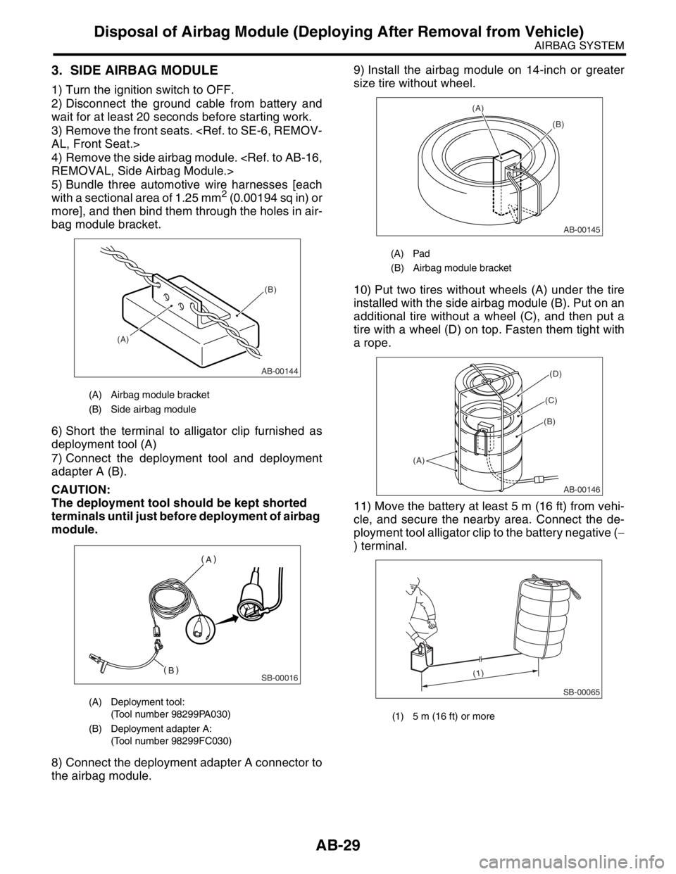
5) Bundle three automotive wire harnesses [each
with a sectional area of 1.25 mm
2 (0.00194 sq in) or
more], and then bind them through the holes in air-
bag module bracket.
6) Short the terminal to alligator clip furnished as
deployment tool (A)
7) Connect the deployment tool and deployment
adapter A (B).
CAUTION:
The deployment tool should be kept shorted
terminals until just before deployment of airbag
module.
8) Connect the deployment adapter A connector to
the airbag module.9) Install the airbag module on 14-inch or greater
size tire without wheel.
10) Put two tires without wheels (A) under the tire
installed with the side airbag module (B). Put on an
additional tire without a wheel (C), and then put a
tire with a wheel (D) on top. Fasten them tight with
a rope.
11) Move the battery at least 5 m (16 ft) from vehi-
cle, and secure the nearby area. Connect the de-
ployment tool alligator clip to the battery negative (−
) terminal.
(A) Airbag module bracket
(B) Side airbag module
(A) Deployment tool:
(Tool number 98299PA030)
(B) Deployment adapter A:
(Tool number 98299FC030)
AB-00144
(A)(B)
SB-00016
(A) Pad
(B) Airbag module bracket
(1) 5 m (16 ft) or more
AB-00145
(A)
(B)
AB-00146
(A)
(B)
(C)
(D)
SB-00065
(1)
Page 525 of 2870

EI-49
EXTERIOR/INTERIOR TRIM
Floor Mat
23.Floor Mat
A: REMOVAL
1) Remove the front seats.
2) Remove the rear seat cushion.
3) Remove the console box.
4) Remove the side sill front cover, side sill rear
cover and center pillar lower trim.
5) Remove the footrest or clips from floor mat.
6) Remove the mat hook.
7) Remove the mat from toe board area.
8) Remove the mat from rear heater duct.
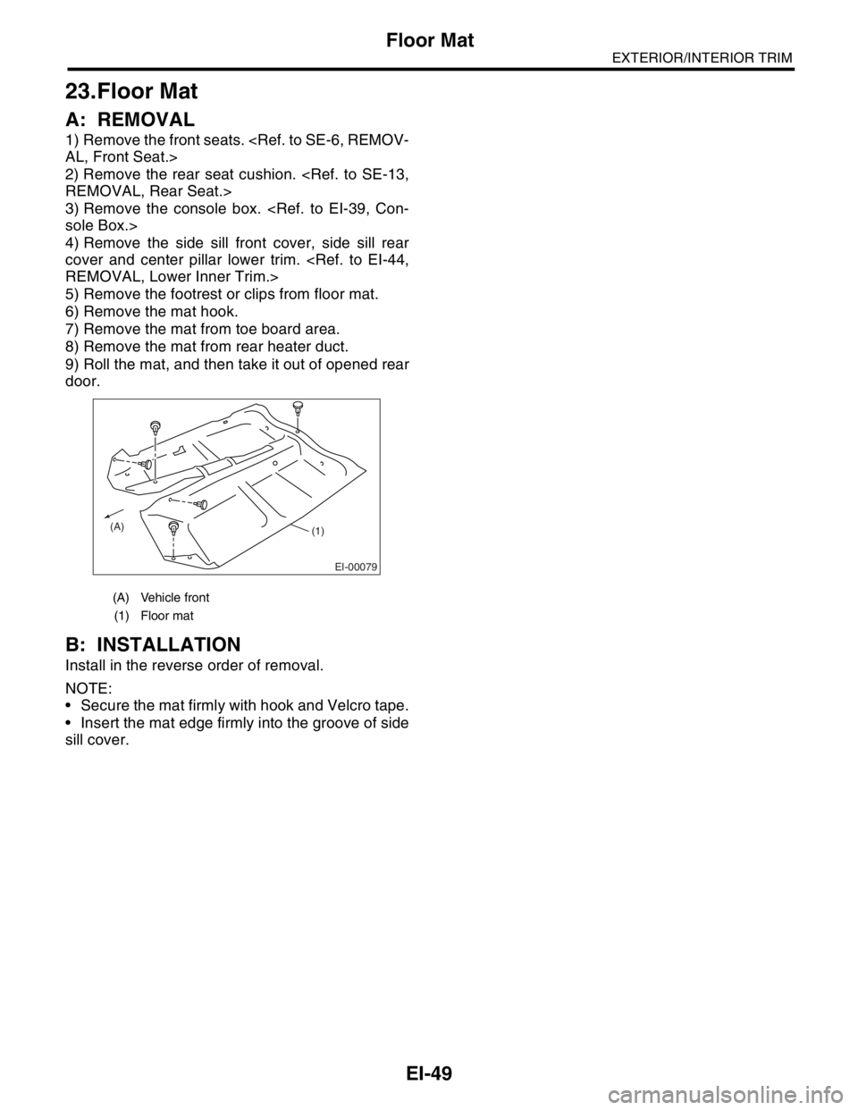
9) Roll the mat, and then take it out of opened rear
door.
B: INSTALLATION
Install in the reverse order of removal.
NOTE:
Secure the mat firmly with hook and Velcro tape.
Insert the mat edge firmly into the groove of side
sill cover.
(A) Vehicle front
(1) Floor mat
EI-00079
(A)(1)
Page 884 of 2870

ME(H4SO)-15
MECHANICAL
General Description
C: CAUTION
Wear working clothing, including a cap, protec-
tive goggles and protective shoes during operation.
Remove contamination including dirt and corro-
sion before removal, installation or disassembly.
Keep the disassembled parts in order and pro-
tect them from dust or dirt.
Before removal, installation or disassembly, be
sure to clarify the failure. Avoid unnecessary re-
moval, installation, disassembly and replacement.
Be careful not to burn yourself, because each
part in the vehicle is hot after running.
Be sure to tighten bolts and nuts to the specified
torque.
Place shop jacks or rigid racks at the specified
points.
Before disconnecting electrical connectors of
sensors or units, be sure to disconnect the ground
cable from battery.
All parts should be thoroughly cleaned, paying
special attention to the engine oil passages, pis-
tons and bearings. Rotating parts and sliding parts such as piston,
bearing and gear should be coated with oil prior to
assembly.
Be careful not to let oil, grease or coolant contact
the timing belt, clutch disc and flywheel.
All removed parts, if to be reused, should be re-
installed in the original positions and directions.
Bolts, nuts and washers should be replaced with
new ones as required.
Even if necessary inspections have been made
in advance, proceed with assembly work while
making rechecks.
Remove or install engine in an area where chain
hoists, lifting devices, etc. are available for ready
use.
Be sure not to damage coated surfaces of body
panels with tools, or not to stain seats and windows
with coolant or oil. Place a cover over fenders, as
required, for protection.
Prior to starting work, prepare the following:
Service tools, clean cloth, containers to catch cool-
ant and oil, wire ropes, chain hoist, transmission
jacks, etc.
Lift-up or lower the vehicle when necessary.
Make sure to support the correct positions.
D: PREPARATION TOOL
1. SPECIAL TOOL
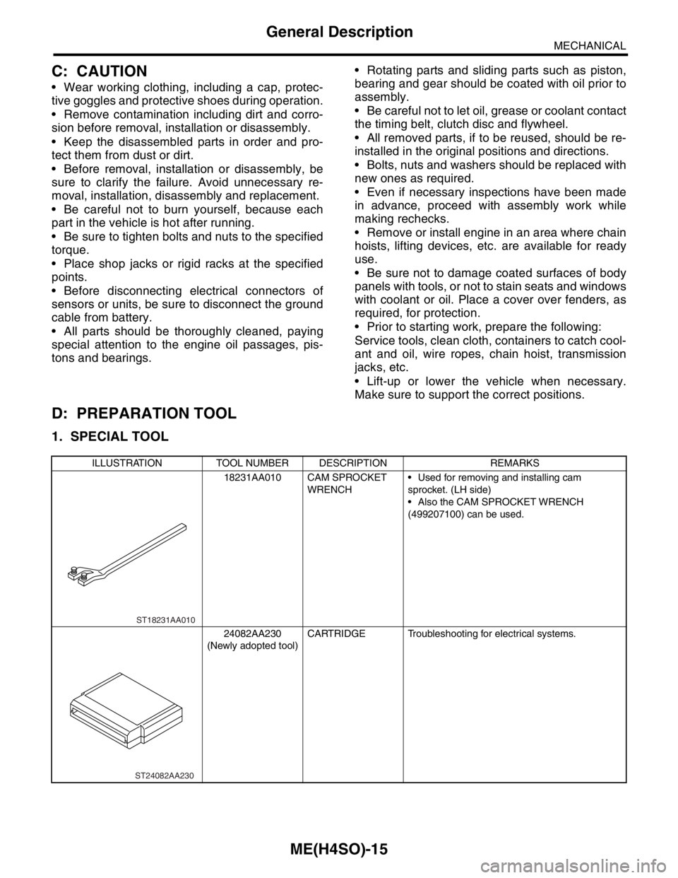
ILLUSTRATION TOOL NUMBER DESCRIPTION REMARKS
18231AA010 CAM SPROCKET
WRENCH Used for removing and installing cam
sprocket. (LH side)
Also the CAM SPROCKET WRENCH
(499207100) can be used.
24082AA230
(Newly adopted tool)CARTRIDGE Troubleshooting for electrical systems.
ST18231AA010
ST24082AA230
Page 1478 of 2870

ME(H4DOTC)-22
MECHANICAL
General Description
C: CAUTION
Wear working clothing, including a cap, protec-
tive goggles, and protective shoes during opera-
tion.
Remove contamination including dirt and corro-
sion before removal, installation or disassembly.
Keep the disassembled parts in order and pro-
tect them from dust or dirt.
Before removal, installation or disassembly, be
sure to clarify the failure. Avoid unnecessary re-
moval, installation, disassembly, and replacement.
Be careful not to burn yourself, because each
part in the vehicle is hot after running.
Be sure to tighten fasteners including bolts and
nuts to the specified torque.
Place shop jacks or rigid racks at the specified
points.
Before disconnecting electrical connectors of
sensors or units, be sure to disconnect the ground
cable from battery.
All parts should be thoroughly cleaned, paying
special attention to the engine oil passages, pis-
tons and bearings.
Rotating parts and sliding parts such as piston,
bearing and gear should be coated with oil prior to
assembly.
Be careful not to let oil, grease or coolant contact
the timing belt, clutch disc and flywheel.
All removed parts, if to be reused, should be re-
installed in the original positions and directions.
Bolts, nuts and washers should be replaced with
new ones as required.
Even if necessary inspections have been made
in advance, proceed with assembly work while
making rechecks.
Remove or install the engine in an area where
chain hoists, lifting devices, etc. are available for
ready use.
Be sure not to damage coated surfaces of body
panels with tools or stain seats and windows with
coolant or oil. Place a cover over fenders, as re-
quired, for protection.
Prior to starting work, prepare the following:
Service tools, clean cloth, containers to catch cool-
ant and oil, wire ropes, chain hoist, transmission
jacks, etc.
Lift-up or lower the vehicle when necessary.
Make sure to support the correct positions.
Page 1536 of 2870

ME(H4DOTC)-78
MECHANICAL
Cylinder Head Assembly
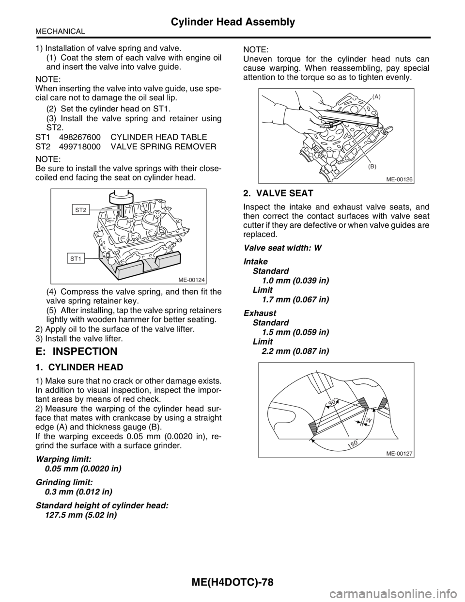
1) Installation of valve spring and valve.
(1) Coat the stem of each valve with engine oil
and insert the valve into valve guide.
NOTE:
When inserting the valve into valve guide, use spe-
cial care not to damage the oil seal lip.
(2) Set the cylinder head on ST1.
(3) Install the valve spring and retainer using
ST2.
ST1 498267600 CYLINDER HEAD TABLE
ST2 499718000 VALVE SPRING REMOVER
NOTE:
Be sure to install the valve springs with their close-
coiled end facing the seat on cylinder head.
(4) Compress the valve spring, and then fit the
valve spring retainer key.
(5) After installing, tap the valve spring retainers
lightly with wooden hammer for better seating.
2) Apply oil to the surface of the valve lifter.
3) Install the valve lifter.
E: INSPECTION
1. CYLINDER HEAD
1) Make sure that no crack or other damage exists.
In addition to visual inspection, inspect the impor-
tant areas by means of red check.
2) Measure the warping of the cylinder head sur-
face that mates with crankcase by using a straight
edge (A) and thickness gauge (B).
If the warping exceeds 0.05 mm (0.0020 in), re-
grind the surface with a surface grinder.
Warping limit:
0.05 mm (0.0020 in)
Grinding limit:
0.3 mm (0.012 in)
Standard height of cylinder head:
127.5 mm (5.02 in)NOTE:
Uneven torque for the cylinder head nuts can
cause warping. When reassembling, pay special
attention to the torque so as to tighten evenly.
2. VALVE SEAT
Inspect the intake and exhaust valve seats, and
then correct the contact surfaces with valve seat
cutter if they are defective or when valve guides are
replaced.
Valve seat width: W
Intake
Standard
1.0 mm (0.039 in)
Limit
1.7 mm (0.067 in)
Exhaust
Standard
1.5 mm (0.059 in)
Limit
2.2 mm (0.087 in)
ME-00124
ST1
ST2
ME-00126
(A)
(B)
ME-00127
W