tires SUBARU FORESTER 2004 Service Repair Manual
[x] Cancel search | Manufacturer: SUBARU, Model Year: 2004, Model line: FORESTER, Model: SUBARU FORESTER 2004Pages: 2870, PDF Size: 38.67 MB
Page 127 of 2870
AB-27
AIRBAG SYSTEM
Disposal of Airbag Module (Deploying After Removal from Vehicle)
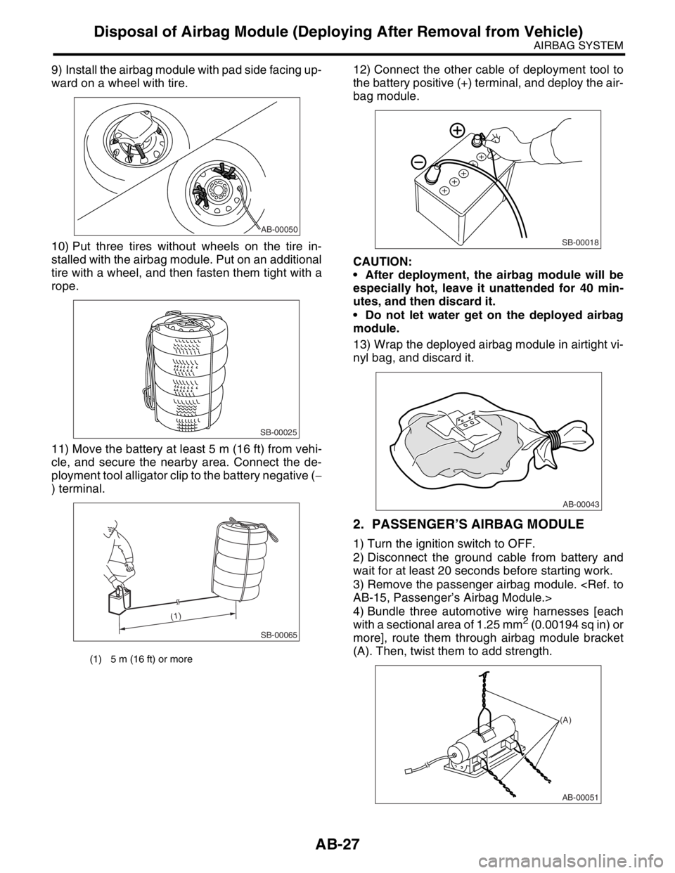
9) Install the airbag module with pad side facing up-
ward on a wheel with tire.
10) Put three tires without wheels on the tire in-
stalled with the airbag module. Put on an additional
tire with a wheel, and then fasten them tight with a
rope.
11) Move the battery at least 5 m (16 ft) from vehi-
cle, and secure the nearby area. Connect the de-
ployment tool alligator clip to the battery negative (−
) terminal.12) Connect the other cable of deployment tool to
the battery positive (+) terminal, and deploy the air-
bag module.
CAUTION:
After deployment, the airbag module will be
especially hot, leave it unattended for 40 min-
utes, and then discard it.
Do not let water get on the deployed airbag
module.
13) Wrap the deployed airbag module in airtight vi-
nyl bag, and discard it.
2. PASSENGER’S AIRBAG MODULE
1) Turn the ignition switch to OFF.
2) Disconnect the ground cable from battery and
wait for at least 20 seconds before starting work.
3) Remove the passenger airbag module.
4) Bundle three automotive wire harnesses [each
with a sectional area of 1.25 mm
2 (0.00194 sq in) or
more], route them through airbag module bracket
(A). Then, twist them to add strength.
(1) 5 m (16 ft) or more
AB-00050
SB-00025
SB-00065
(1)
SB-00018
AB-00043
AB-00051
(A)
Page 128 of 2870
AB-28
AIRBAG SYSTEM
Disposal of Airbag Module (Deploying After Removal from Vehicle)
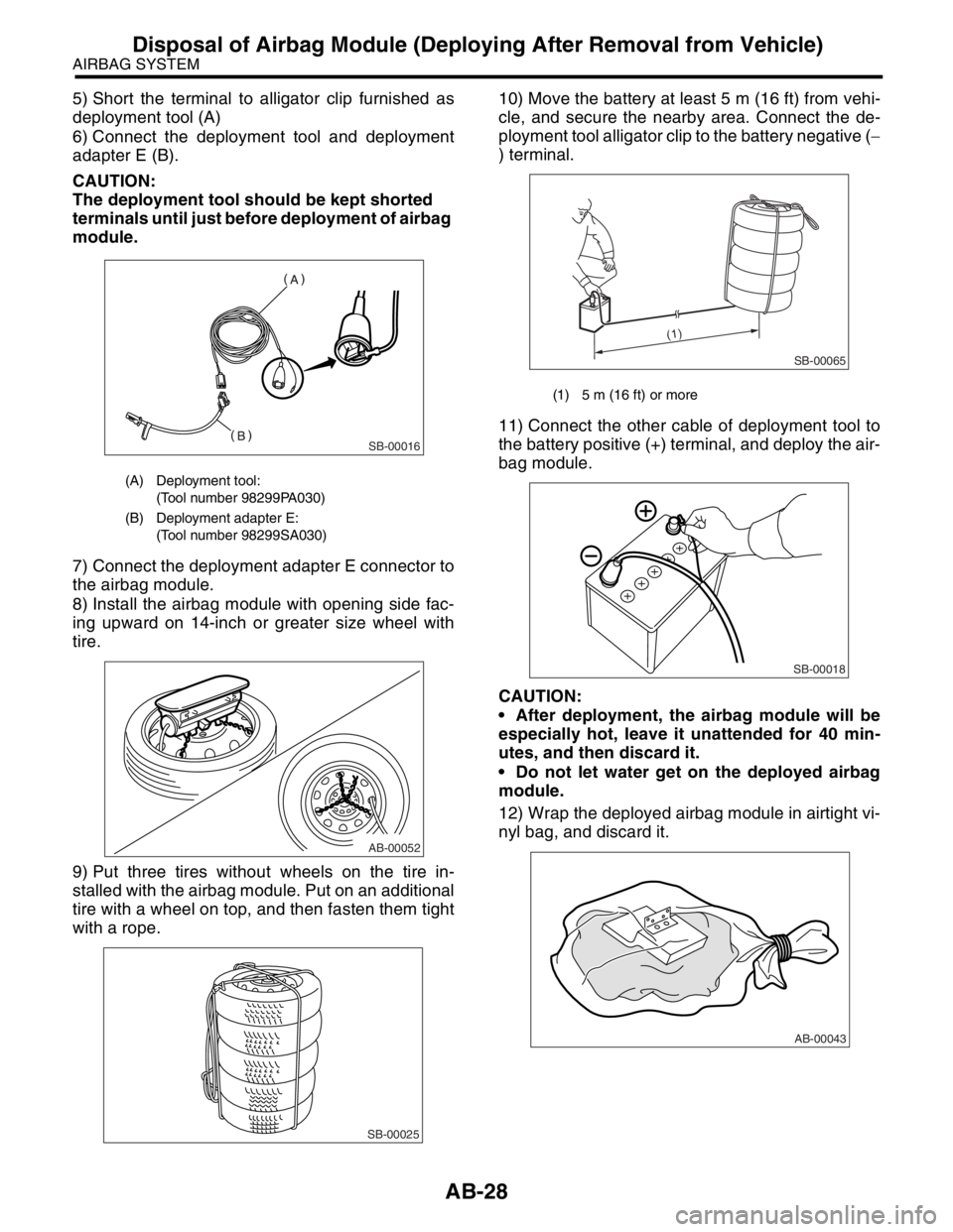
5) Short the terminal to alligator clip furnished as
deployment tool (A)
6) Connect the deployment tool and deployment
adapter E (B).
CAUTION:
The deployment tool should be kept shorted
terminals until just before deployment of airbag
module.
7) Connect the deployment adapter E connector to
the airbag module.
8) Install the airbag module with opening side fac-
ing upward on 14-inch or greater size wheel with
tire.
9) Put three tires without wheels on the tire in-
stalled with the airbag module. Put on an additional
tire with a wheel on top, and then fasten them tight
with a rope.10) Move the battery at least 5 m (16 ft) from vehi-
cle, and secure the nearby area. Connect the de-
ployment tool alligator clip to the battery negative (−
) terminal.
11) Connect the other cable of deployment tool to
the battery positive (+) terminal, and deploy the air-
bag module.
CAUTION:
After deployment, the airbag module will be
especially hot, leave it unattended for 40 min-
utes, and then discard it.
Do not let water get on the deployed airbag
module.
12) Wrap the deployed airbag module in airtight vi-
nyl bag, and discard it.
(A) Deployment tool:
(Tool number 98299PA030)
(B) Deployment adapter E:
(Tool number 98299SA030)
SB-00016
AB-00052
SB-00025
(1) 5 m (16 ft) or more
SB-00065
(1)
SB-00018
AB-00043
Page 129 of 2870
AB-29
AIRBAG SYSTEM
Disposal of Airbag Module (Deploying After Removal from Vehicle)
3. SIDE AIRBAG MODULE
1) Turn the ignition switch to OFF.
2) Disconnect the ground cable from battery and
wait for at least 20 seconds before starting work.
3) Remove the front seats.
4) Remove the side airbag module.
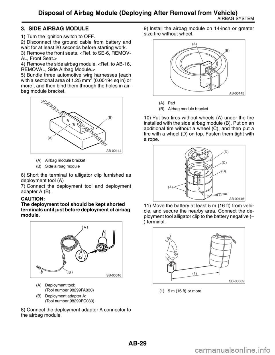
5) Bundle three automotive wire harnesses [each
with a sectional area of 1.25 mm
2 (0.00194 sq in) or
more], and then bind them through the holes in air-
bag module bracket.
6) Short the terminal to alligator clip furnished as
deployment tool (A)
7) Connect the deployment tool and deployment
adapter A (B).
CAUTION:
The deployment tool should be kept shorted
terminals until just before deployment of airbag
module.
8) Connect the deployment adapter A connector to
the airbag module.9) Install the airbag module on 14-inch or greater
size tire without wheel.
10) Put two tires without wheels (A) under the tire
installed with the side airbag module (B). Put on an
additional tire without a wheel (C), and then put a
tire with a wheel (D) on top. Fasten them tight with
a rope.
11) Move the battery at least 5 m (16 ft) from vehi-
cle, and secure the nearby area. Connect the de-
ployment tool alligator clip to the battery negative (−
) terminal.
(A) Airbag module bracket
(B) Side airbag module
(A) Deployment tool:
(Tool number 98299PA030)
(B) Deployment adapter A:
(Tool number 98299FC030)
AB-00144
(A)(B)
SB-00016
(A) Pad
(B) Airbag module bracket
(1) 5 m (16 ft) or more
AB-00145
(A)
(B)
AB-00146
(A)
(B)
(C)
(D)
SB-00065
(1)
Page 250 of 2870
SB-16
SEAT BELT SYSTEM
Disposal of Pretensioner
2. DEPLOYING OF RETRACTOR PRETEN-
SIONER AFTER REMOVAL FROM VEHICLE
1) Fold backrest all the way forward, then move
front seat all the way forward.
2) Turn the ignition switch to OFF, disconnect the
ground cable from battery, and wait for more than
20 seconds before starting work.
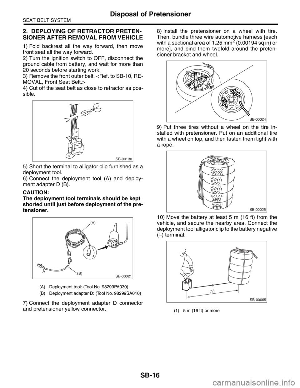
3) Remove the front outer belt.
4) Cut off the seat belt as close to retractor as pos-
sible.
5) Short the terminal to alligator clip furnished as a
deployment tool.
6) Connect the deployment tool (A) and deploy-
ment adapter D (B).
CAUTION:
The deployment tool terminals should be kept
shorted until just before deployment of the pre-
tensioner.
7) Connect the deployment adapter D connector
and pretensioner yellow connector.8) Install the pretensioner on a wheel with tire.
Then, bundle three wire automotive harness [each
with a sectional area of 1.25 mm
2 (0.00194 sq in) or
more], and bind them twofold around the preten-
sioner bracket and wheel.
9) Put three tires without a wheel on the tire in-
stalled with pretensioner. Put on an additional tire
with a wheel on top, and then fasten them tight with
a rope.
10) Move the battery at least 5 m (16 ft) from the
vehicle, and secure the nearby area. Connect the
deployment tool alligator clip to the battery negative
(−) terminal.
(A) Deployment tool: (Tool No. 98299PA030)
(B) Deployment adapter D: (Tool No. 98299SA010)
SB-00130
SB-00021
(A)
(B)
(1) 5 m (16 ft) or more
SB-00024
SB-00025
SB-00065
(1)
Page 251 of 2870
SB-17
SEAT BELT SYSTEM
Disposal of Pretensioner
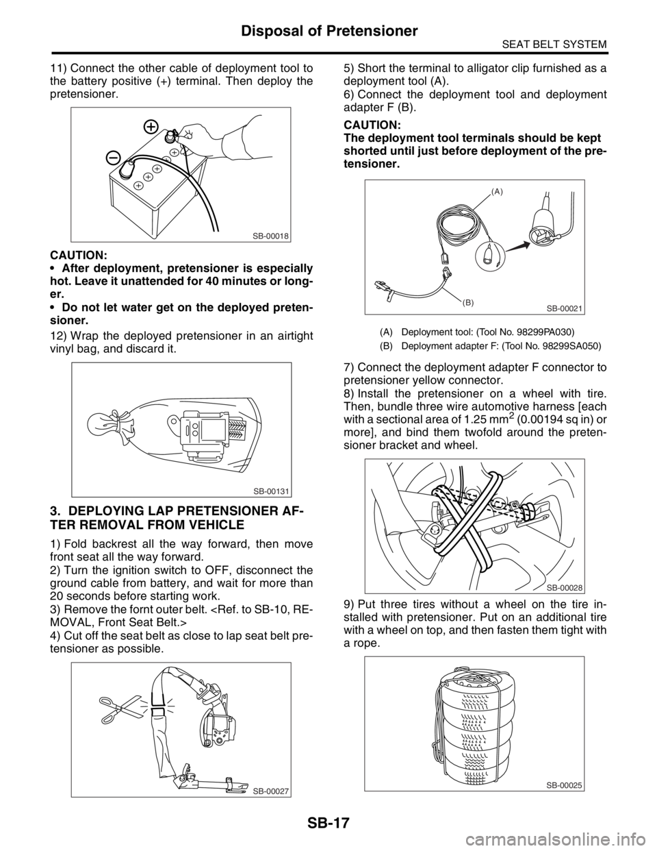
11) Connect the other cable of deployment tool to
the battery positive (+) terminal. Then deploy the
pretensioner.
CAUTION:
After deployment, pretensioner is especially
hot. Leave it unattended for 40 minutes or long-
er.
Do not let water get on the deployed preten-
sioner.
12) Wrap the deployed pretensioner in an airtight
vinyl bag, and discard it.
3. DEPLOYING LAP PRETENSIONER AF-
TER REMOVAL FROM VEHICLE
1) Fold backrest all the way forward, then move
front seat all the way forward.
2) Turn the ignition switch to OFF, disconnect the
ground cable from battery, and wait for more than
20 seconds before starting work.
3) Remove the fornt outer belt.
4) Cut off the seat belt as close to lap seat belt pre-
tensioner as possible.5) Short the terminal to alligator clip furnished as a
deployment tool (A).
6) Connect the deployment tool and deployment
adapter F (B).
CAUTION:
The deployment tool terminals should be kept
shorted until just before deployment of the pre-
tensioner.
7) Connect the deployment adapter F connector to
pretensioner yellow connector.
8) Install the pretensioner on a wheel with tire.
Then, bundle three wire automotive harness [each
with a sectional area of 1.25 mm
2 (0.00194 sq in) or
more], and bind them twofold around the preten-
sioner bracket and wheel.
9) Put three tires without a wheel on the tire in-
stalled with pretensioner. Put on an additional tire
with a wheel on top, and then fasten them tight with
a rope.
SB-00018
SB-00131
SB-00027
(A) Deployment tool: (Tool No. 98299PA030)
(B) Deployment adapter F: (Tool No. 98299SA050)
SB-00021
(A)
(B)
SB-00028
SB-00025
Page 268 of 2870
LI-14
LIGHTING SYSTEM
Headlight Assembly
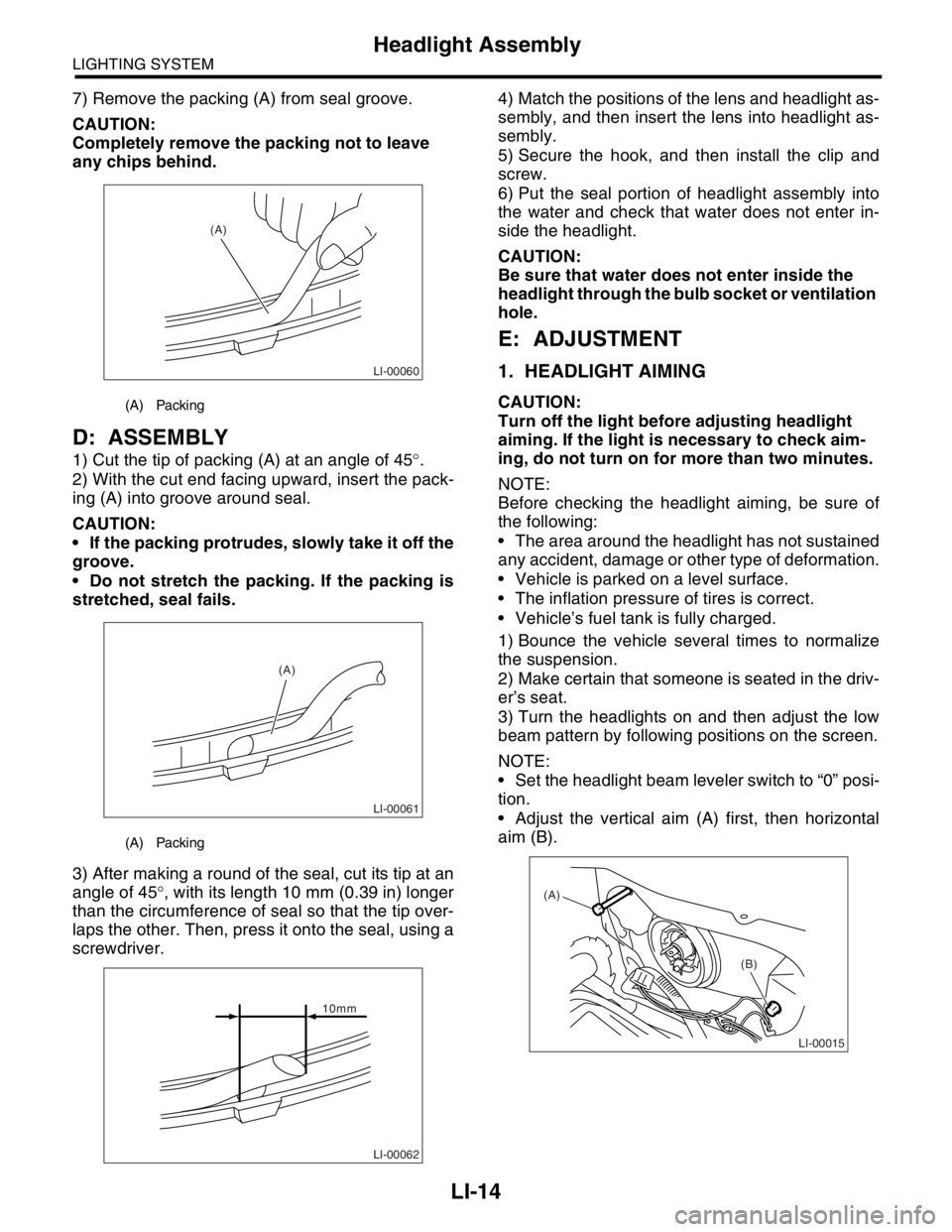
7) Remove the packing (A) from seal groove.
CAUTION:
Completely remove the packing not to leave
any chips behind.
D: ASSEMBLY
1) Cut the tip of packing (A) at an angle of 45°.
2) With the cut end facing upward, insert the pack-
ing (A) into groove around seal.
CAUTION:
If the packing protrudes, slowly take it off the
groove.
Do not stretch the packing. If the packing is
stretched, seal fails.
3) After making a round of the seal, cut its tip at an
angle of 45°, with its length 10 mm (0.39 in) longer
than the circumference of seal so that the tip over-
laps the other. Then, press it onto the seal, using a
screwdriver.4) Match the positions of the lens and headlight as-
sembly, and then insert the lens into headlight as-
sembly.
5) Secure the hook, and then install the clip and
screw.
6) Put the seal portion of headlight assembly into
the water and check that water does not enter in-
side the headlight.
CAUTION:
Be sure that water does not enter inside the
headlight through the bulb socket or ventilation
hole.
E: ADJUSTMENT
1. HEADLIGHT AIMING
CAUTION:
Turn off the light before adjusting headlight
aiming. If the light is necessary to check aim-
ing, do not turn on for more than two minutes.
NOTE:
Before checking the headlight aiming, be sure of
the following:
The area around the headlight has not sustained
any accident, damage or other type of deformation.
Vehicle is parked on a level surface.
The inflation pressure of tires is correct.
Vehicle’s fuel tank is fully charged.
1) Bounce the vehicle several times to normalize
the suspension.
2) Make certain that someone is seated in the driv-
er’s seat.
3) Turn the headlights on and then adjust the low
beam pattern by following positions on the screen.
NOTE:
Set the headlight beam leveler switch to “0” posi-
tion.
Adjust the vertical aim (A) first, then horizontal
aim (B).(A) Packing
(A) Packing
LI-00060
(A)
LI-00061
(A)
LI-00062
10mm
LI-00015
(A)
(B)
Page 726 of 2870

PI-3
PRE-DELIVERY INSPECTION
Pre-delivery Inspection
B: PDI PROCEDURE
Follow the procedures shown in the table below.
Static Checks Just After Vehicle Receipt
Step Check point
1. Appearance check (1) If the vehicle is covered with protective coating, visually check the vehicle
body for damage and dents. If the protective coating has been removed,
visually check the body paints for small areas of damage or stains.
(2) Visually check the glass and light lenses for any damage and cracks or
excessive gaps to the body sheet metal.
(3) Visually check the plated parts for any damage.
2. Tire check (1) Check the tires for damage, abnormal conditions, and dents on the
wheels.
(2) Check the tire air pressure.
3. Fuse installation If the vehicle is about to be delivered to the customer, attach a room light
fuse.
4. Connection of air conditioner harness If the vehicle is about to be delivered to the customer, connect the air condi-
tioner harness.
5. Check the doors for lock/unlock and open/close
operations.(1) Using the key, check if the door can be locked and unlocked normally.
(2) Open and close all doors to see that there are no abnormal conditions.
6. Operation check of double lock Check that the double lock operates normally.
7. Operation check of the child safety lock system. Check the child safety lock system operates normally.
8. Check the rear gate for lock/unlock and open/
close operations.(1) Check if the rear gate can be unlocked normally from the emergency
door.
(2) Open and close the rear gate to see that there are no abnormal condi-
tions.
(3) Operate the power door locking switch to check that the rear gate is
locked and unlocked normally.
9. Operation check of fuel lid opener lock release
leverOperate the fuel lid opener to check that the fuel lid is unlocked normally.
10. Accessory check Check that the following accessories are provided:
Owner’s manual
Warranty booklet
Service booklet
Spare key
Jack
Tool set
Spare tire
11. Operation check of hood lock release system Operate the hood lock release lever to check that the hood opens normally.
12. Battery Check the battery for any abnormal conditions such as rust and trace of bat-
tery fluid leaks.
13. Brake fluid Check the fluid amount.
14. Engine oil Check the oil amount.
15. Transmission fluid (1) Check the fluid amount.
(2) For AT, check the front differential oil.
16. AT front differential oil Check the AT front differential oil amount.
17. Coolant Check the coolant amount.
18. Clutch fluid Check the clutch fluid amount.
19. Window washer fluid Check the window washer fluid amount.
20. Hood latch check Check that the hood is closed and latched securely.
21. Keyless entry system Check that the keyless entry system operates normally.
22. Security system Check that the security system operates normally.
23. Seat (1) Check the seat surfaces for smears or dirt.
(2) Check the seat installation conditions and functionality.
24. Seat belt Check the seat belt installation conditions and functionality.
25. Wheel alignment Check that the wheel alignments are properly adjusted.
Page 777 of 2870
PM-40
PERIODIC MAINTENANCE SERVICE
Tire Rotation
25.Tire Rotation
A: INSPECTION
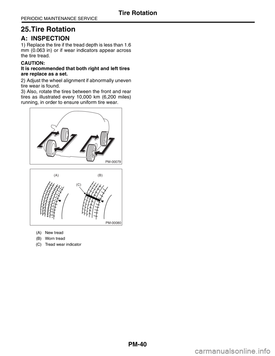
1) Replace the tire if the tread depth is less than 1.6
mm (0.063 in) or if wear indicators appear across
the tire tread.
CAUTION:
It is recommended that both right and left tires
are replace as a set.
2) Adjust the wheel alignment if abnormally uneven
tire wear is found.
3) Also, rotate the tires between the front and rear
tires as illustrated every 10,000 km (6,200 miles)
running, in order to ensure uniform tire wear.
(A) New tread
(B) Worn tread
(C) Tread wear indicator
PM-00079
PM-00080
(A) (B)
(C)