air condition SUBARU FORESTER 2009 SH / 3.G User Guide
[x] Cancel search | Manufacturer: SUBARU, Model Year: 2009, Model line: FORESTER, Model: SUBARU FORESTER 2009 SH / 3.GPages: 384, PDF Size: 13.91 MB
Page 129 of 384

3-18Instruments and controls
engine has started.
This light illuminates when All-Wheel
Drive is disengaged and the drive me-
chanism is switched to Front Wheel Drive
for maintenance or similar purposes.
It flashes if the vehicle is driven with tires
of differing diameters fitted on the wheels
or with an excessively low air pressure in
any of the tires.
CAUTION
Continuing to drive with the AWD
warning light flashing can damage
the powertrain. If the AWD warning
light starts to flash, promptly park in
a safe place and check whether the
tires have differing diameters and
whether any of the tires has an
excessively low inflation pressure.
& Vehicle Dynamics
Control operation indi-
cator light
This light illuminates when the ignition
switch is ON and turns off approximately 2
seconds later.
It blinks when the skid suppression func-
tion is activated. It illuminates when only
the traction control function is operating.
The Vehicle Dynamics Control system is probably malfunctioning under any of the
following conditions. Have your vehicle
checked at a SUBARU dealer immedi-
ately. .
The light does not illuminate when the
ignition switch is turned to the “ON ”
position.. The light does not turn off even after a
period of approximately 2 seconds after
the ignition switch has been turned to the“ ON ”position.
& Vehicle Dynamics
Control warning light/
Vehicle Dynamics Con-
trol OFF indicator light
This warning light has both the function of
indicating malfunctions in the Vehicle
Dynamics Control system and the function
of indicating that the Vehicle Dynamics
Control system has been deactivated.
It illuminates in the event of a malfunction
in the system and is on when the system
is not operating.
This warning light illuminates when the
ignition switch is turned to the “ON ”
position and turns off several seconds
after the engine has started. It indicates
that the Vehicle Dynamics Control system
is in normal operation. !
Vehicle Dynamics Control warninglight
The Vehicle Dynamics Control system is
probably inoperative under any of the
following conditions. Have your vehicle
checked at a SUBARU dealer immedi-
ately. . The warning light does not illuminate
when the ignition switch is turned to the “ ON ”position.
. The warning light illuminates while the
vehicle is running. . If the electrical circuit of the Vehicle
Dynamics Control system itself becomes
faulty, the warning light only illuminates. At
this time, the ABS (Anti-lock Brake Sys-
tem) remains fully operational. . The warning light illuminates when the
electronic control system of the ABS/
Vehicle Dynamics Control system mal-functions.
The Vehicle Dynamics Control system
provides its ABS control through the
electrical circuit of the ABS system.
Accordingly, if the ABS is inoperative, the
Vehicle Dynamics Control system be-
comes unable to provide ABS control. As
a result, the Vehicle Dynamics Control
system also becomes inoperative, caus-
ing the warning light to illuminate. Though
both the Vehicle Dynamics Control and
Page 137 of 384
3-26Instruments and controls
&Automatic headlight beam
leveler (vehicles with HID headlights)
The HID headlights generate more light
than conventional halogen headlights.
Therefore a driver of an oncoming vehicle
may experience too much glare when your
headlight beam height adjustment is high
due to the vehicle carrying heavy load.
The automatic headlight beam leveler
adjusts the headlight beam height auto-
matically and optimally according to the
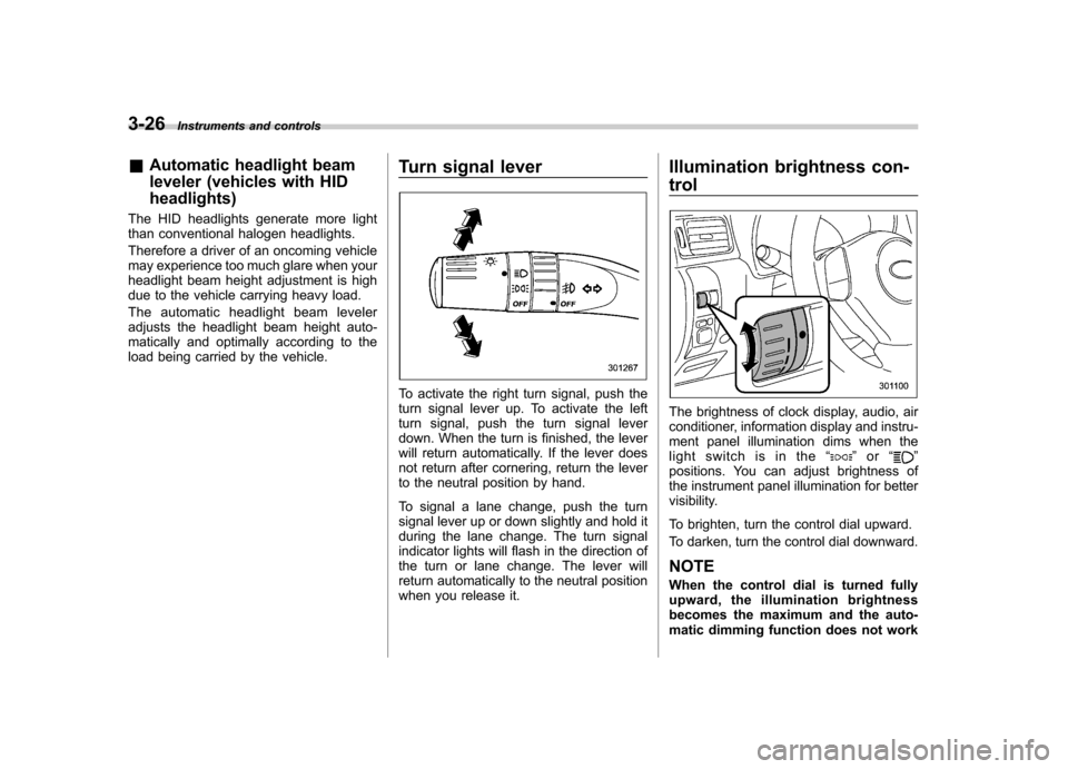
load being carried by the vehicle. Turn signal lever
To activate the right turn signal, push the
turn signal lever up. To activate the left
turn signal, push the turn signal lever
down. When the turn is finished, the lever
will return automatically. If the lever does
not return after cornering, return the lever
to the neutral position by hand.
To signal a lane change, push the turn
signal lever up or down slightly and hold it
during the lane change. The turn signal
indicator lights will flash in the direction of
the turn or lane change. The lever will
return automatically to the neutral position
when you release it.Illumination brightness con- trol
The brightness of clock display, audio, air
conditioner, information display and instru-
ment panel illumination dims when the
light switch is in the
“
”or “”
positions. You can adjust brightness of
the instrument panel illumination for better
visibility.
To brighten, turn the control dial upward.
To darken, turn the control dial downward.
NOTE
When the control dial is turned fully
upward, the illumination brightness
becomes the maximum and the auto-
matic dimming function does not work
Page 145 of 384

3-34Instruments and controls
! Auto-dimming mirror/compass (if equipped)
1) Left button
2) Auto dimming indicator
3) Photosensor
4) Right button
The auto-dimming mirror has an anti-glare
feature which automatically reduces glare
coming from headlights of vehicles behind
you. It also contains a built-in compass. . By pressing and releasing the left
button, the automatic dimming function is
toggled on or off. When the automatic
dimming function is on, the auto dimming
indicator light (green) located to the right
of the button will illuminate. . By pressing and releasing the right
button, the compass display is toggled on or off. When the compass is on, an
illuminated compass reading will appear
in the lower part of the mirror.
Even with the mirror in anti-glare mode,
the mirror surface turns bright if the
transmission is shifted into reverse. This
is to ensure good rearward visibility duringreversing. !
Photosensors
The mirror has a photosensor attached on
both the front and back sides. If the glare
from the headlights of vehicles behind you
strikes the mirror, these sensors detect it
and make the reflection surface of the
mirror dimmer to help prevent you from
being blinded. For this reason, use care
not to cover the sensors with stickers, or
other similar items. Periodically wipe the sensors clean using a piece of dry soft
cotton cloth or an applicator. !
Compass calibration
1. For optimum calibration, switch off all
nonessential electrical accessories (rear
window defogger, heater/air conditioning
system, spotlight, etc.) and ensure all
doors are shut.
2. Drive to an open, level area away from
large metallic objects or structures and
make certain the ignition switch is in the“ ON ”position.
3. Press and hold the left button for 3
seconds then release, and the compass
will enter the calibration mode. “CAL ”and
direction will be displayed.
4. Drive slowly in a circle until “CAL ”
disappears from the display (approxi-
mately two or three circles). The compass
is now calibrated.
5. Further calibration may be necessary
should outside influences cause the mirror
to read inaccurately. You will know that
this has occurred if your compass begins
to read in only limited directions. Should
you encounter this situation, return to step
one of the above procedure and recali-
brate the mirror.
Page 150 of 384

Ventilator.............................................................. 4-2
Air flow selection ................................................ 4-2
Center and side ventilators .................................. 4-3
Manual climate control system (if equipped) ..................................................... 4-3
Control panel ...................................................... 4-3
Heater operation ................................................. 4-5
Air conditioner operation ..................................... 4-7
Automatic climate control system (if equipped) ..................................................... 4-8
Control panel ...................................................... 4-8
To use as full-automatic climate control system .............................................................. 4-8
To use as semi-automatic climate control system .............................................................. 4-8
Fan speed control dial ......................................... 4-9
Temperature control dial ...................................... 4-9
Air flow control dial ............................................. 4-9
Air inlet selection button .................................... 4-10 Air conditioner button
........................................ 4-10
Temperature sensors ......................................... 4-11
Operating tips for heater and air conditioner ...................................................... 4-12
Cleaning ventilation grille ................................... 4-12
Efficient cooling after parking in direct sunlight ........................................................... 4-12
Lubrication oil circulation in the refrigerant circuit .............................................................. 4-12
Checking air conditioning system before summer season ............................................................ 4-12
Cooling and dehumidifying in high humidity and low temperature weather conditions ................. 4-12
Air conditioner compressor shut-off when engine is heavily loaded .............................................. 4-12
Refrigerant for your climate control system ... ..... 4-12
Air filtration system ........................................... 4-13
Replacing an air filter ......................................... 4-13Climate control
4
Page 152 of 384

&Center and side ventilators
! Center ventilators
Move the tab up and down or right and left
to adjust the flow direction. !
Side ventilators
1) Open
2) Close
3) Thumb-wheel
Move the tab up and down or right and left
to adjust the flow direction.
To open or close the ventilator, turn the
thumb-wheel up or down. Manual climate control sys-
tem (if equipped) &
Control panel
1) Temperature control dial
2) Fan speed control dial
3) Air flow control dial
4) Rear window defogger button (Refer to
the“Rear window defogger button ”sec-
tion in chapter 3.)
5) Air conditioner button
6) Air inlet selection button
! Temperature control dial
This dial regulates the temperature of air
flow from the air outlets over a range from
the blue side (cool) to red side (warm). Climate control
4-3
– CONTINUED –
Page 153 of 384
4-4Climate control
! Fan speed control dial
The fan operates only when the ignition
switch is turned to the “ON ”position. The
fan speed control dial is used to select
four fan speeds. ! Air flow control dial
This dial has the following five positions:
: Air flows through the instrument panel
outlets.
: Air flows through the instrument panel
outlets and the foot outlets.
: Air flows through the foot outlets and
some through the windshield defroster outlets.
: Air flows through the windshield
defroster outlets and foot outlets.
: Air flows through the windshield
defroster outlets. NOTE
When the dial is placed in the “
”or
“” position, the air conditioner com-
pressor operates automatically regard-
less of the position of the air condi-
tioner button to defog the windshield
quickly. However the indicator on the
air conditioner button will not illumi-
nate. At the same time, the air inlet
selection is automatically set to “out- side air
”mode.
In this state, you cannot select “recir-
culation ”mode by manually pressing
the air inlet selection button.
Also, you cannot stop the air condi-
tioner compressor by pressing the air
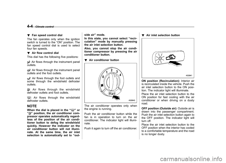
conditioner button. ! Air conditioner button
The air conditioner operates only when
the engine is running.
Push the air conditioner button while the
fan is in operation to turn on the air
conditioner. The indicator light will illumi-nate.
Push it again to turn off the air conditioner. !
Air inlet selection button
ON position (Recirculation): Interior air
is recirculated inside the vehicle. Push the
air inlet selection button to the ON posi-
tion. The indicator light will illuminate.
Place the air inlet selection button to the
ON position for fast cooling with the air
conditioner or when driving on a dustyroad.
OFF position (Outside air): Outside air is
drawn into the passenger compartment.
Push the air inlet selection button again to
the OFF position. The indicator light will
turn off.
Place the air inlet selection button to the
OFF position when the interior has cooled
to a comfortable temperature and the road
is no longer dusty.
Page 154 of 384
WARNING
Continued operation with the air
inletselectionbuttonintheON
position may fog up the windows.
Switch to the OFF position as soon
as the outside dusty conditionclears.
& Heater operation
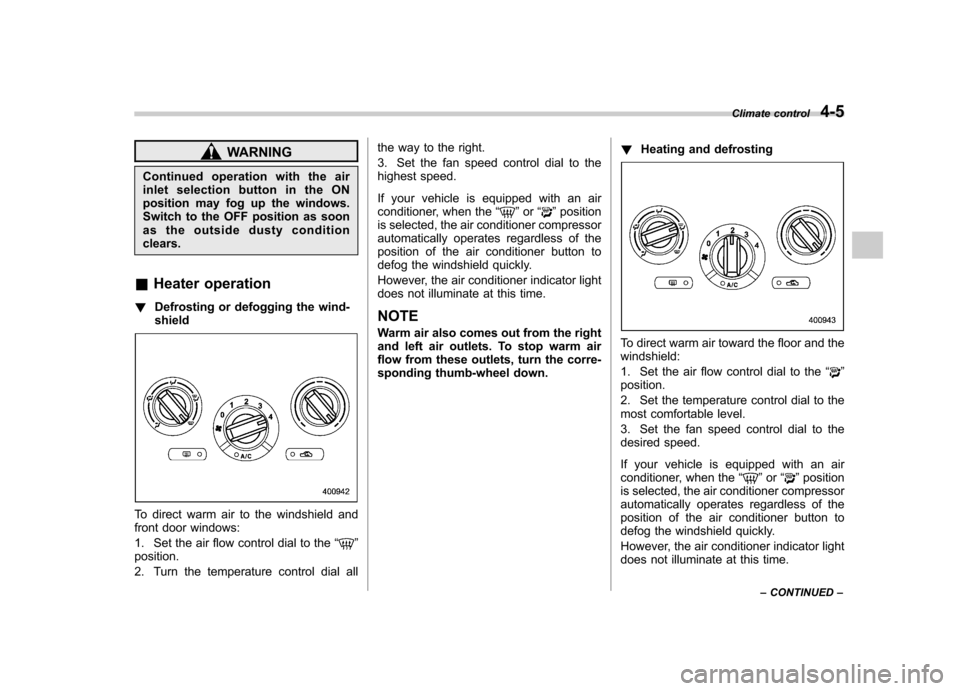
! Defrosting or defogging the wind-shield
To direct warm air to the windshield and
front door windows:
1. Set the air flow control dial to the “
”
position.
2. Turn the temperature control dial all the way to the right.
3. Set the fan speed control dial to the
highest speed.
If your vehicle is equipped with an air
conditioner, when the
“
”or “”position
is selected, the air conditioner compressor
automatically operates regardless of the
position of the air conditioner button to
defog the windshield quickly.
However, the air conditioner indicator light
does not illuminate at this time. NOTE
Warm air also comes out from the right
and left air outlets. To stop warm air
flow from these outlets, turn the corre-
sponding thumb-wheel down. !
Heating and defrosting
To direct warm air toward the floor and the windshield:
1. Set the air flow control dial to the “
”
position.
2. Set the temperature control dial to the
most comfortable level.
3. Set the fan speed control dial to the
desired speed.
If your vehicle is equipped with an air
conditioner, when the “
”or “”position
is selected, the air conditioner compressor
automatically operates regardless of the
position of the air conditioner button to
defog the windshield quickly.
However, the air conditioner indicator light
does not illuminate at this time. Climate control
4-5
– CONTINUED –
Page 156 of 384
When driving on a dusty road, set the air
inlet selection button to the“ON ”position.
WARNING
Continued operation with the air
inletselectionbuttonintheON
position may fog up the windows.
Switch to the OFF position as soon
as the outside dusty conditionclears.
& Air conditioner operation
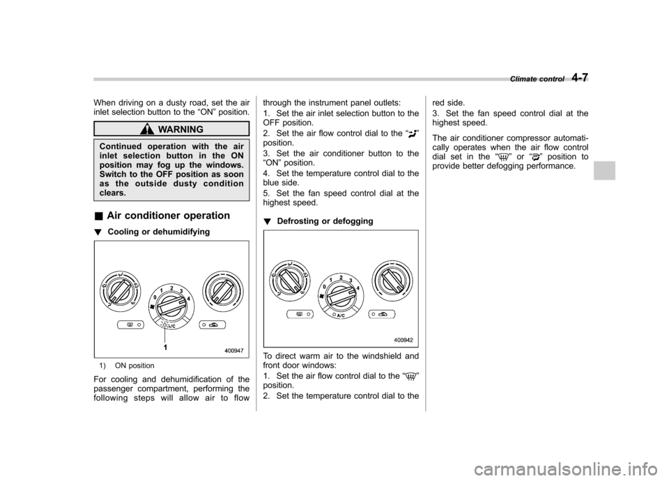
! Cooling or dehumidifying
1) ON position
For cooling and dehumidification of the
passenger compartment, performing the
following steps will allow air to flow through the instrument panel outlets:
1. Set the air inlet selection button to the
OFF position.
2. Set the air flow control dial to the
“
”
position.
3. Set the air conditioner button to the “ ON ”position.
4. Set the temperature control dial to the
blue side.
5. Set the fan speed control dial at the
highest speed. ! Defrosting or defogging
To direct warm air to the windshield and
front door windows:
1. Set the air flow control dial to the “
”
position.
2. Set the temperature control dial to the red side.
3. Set the fan speed control dial at the
highest speed.
The air conditioner compressor automati-
cally operates when the air flow control
dial set in the
“
”or “”position to
provide better defogging performance. Climate control
4-7
Page 157 of 384

4-8Climate control
Automatic climate control
system (if equipped)
Although this climate control system can
be used as a full-automatic climate control
system, it can also, if desired, be used as
a semi-automatic climate control system.
When it is used as a full-automatic climate
control system, the outlet air temperature,
fan speed, air flow distribution, air inlet
control, and air conditioner compressor
operation are all automatically controlled
to maintain a constant, comfortable tem-
perature inside the vehicle. NOTE .Operate the automatic climate con-
trol system when the engine is running. . When the engine coolant is cold, the
blower does not run.. In the “AUTO ”mode, when the air
temperature in the passenger compart-
ment is sufficiently cool, the air condi-
tioner compressor does not operate.
For efficient defogging or dehumidify-
ing in cold weather, press the “A/C ”
button to operate the air conditioner
compressor.. Even when cooling is not necessary,
setting the temperature much lower
than the current outlet air temperature
turns on the air conditioner compres- sor automatically and the
“A/C ”indi-
cator light on the control panel illumi-nates. & Control panel
1) Temperature control dial
2) Fan speed control dial
3) Air flow control dial
4) Rear window defogger button (Refer to
the“Rear window defogger button ”sec-
tion in chapter 3.)
5) Air inlet selection button
6) Air conditioner button
& To use as full-automatic cli-
mate control system
Place the temperature control dial in the
position for your desired temperature, then set the other dials and buttons as de-
scribed in the following. The system
’s
functions will then switch to AUTO mode
and be controlled automatically. . Air flow control dial: AUTO position
. Fan speed control dial: AUTO position
& To use as semi-automatic
climate control system
Each function can be individually set to
AUTO mode independently of the others.
Any function set to AUTO mode is con-
trolled automatically. Any function not set
to AUTO mode can be manually adjusted
as desired.
The temperature can be set within a range
of 65 to 85 8F (20 to 30 8C).
Page 159 of 384
4-10Climate control
: Foot outlets and windshield defroster
outlets (relatively little air from windshield
defroster outlets)
: Windshield defroster outlets and foot
outlets
: Windshield defroster outlets
NOTE
When the dial is placed in the “
”or
“” position, the air inlet selection is
automatically set to “outside air ”
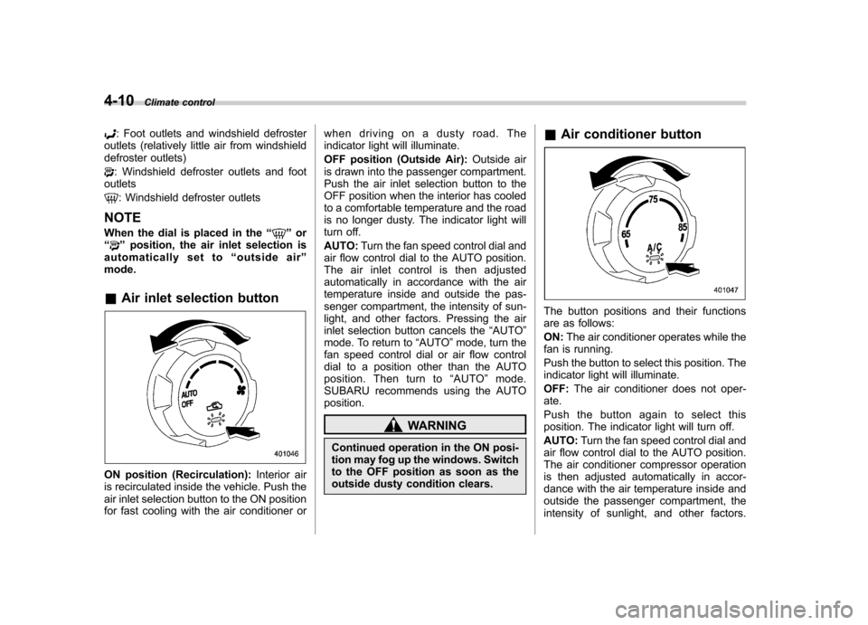
mode. & Air inlet selection button
ON position (Recirculation): Interior air
is recirculated inside the vehicle. Push the
air inlet selection button to the ON position
for fast cooling with the air conditioner or when driving on a dusty road. The
indicator light will illuminate.
OFF position (Outside Air):
Outside air
is drawn into the passenger compartment.
Push the air inlet selection button to the
OFF position when the interior has cooled
to a comfortable temperature and the road
is no longer dusty. The indicator light will
turn off. AUTO: Turn the fan speed control dial and
air flow control dial to the AUTO position.
The air inlet control is then adjusted
automatically in accordance with the air
temperature inside and outside the pas-
senger compartment, the intensity of sun-
light, and other factors. Pressing the air
inlet selection button cancels the “AUTO ”
mode. To return to “AUTO ”mode, turn the
fan speed control dial or air flow control
dial to a position other than the AUTO
position. Then turn to “AUTO ”mode.
SUBARU recommends using the AUTOposition.
WARNING
Continued operation in the ON posi-
tion may fog up the windows. Switch
to the OFF position as soon as the
outside dusty condition clears. &
Air conditioner button
The button positions and their functions
are as follows: ON: The air conditioner operates while the
fan is running.
Push the button to select this position. The
indicator light will illuminate. OFF: The air conditioner does not oper-
ate.
Push the button again to select this
position. The indicator light will turn off. AUTO: Turn the fan speed control dial and
air flow control dial to the AUTO position.
The air conditioner compressor operation
is then adjusted automatically in accor-
dance with the air temperature inside and
outside the passenger compartment, the
intensity of sunlight, and other factors.