oil level SUBARU FORESTER 2009 SH / 3.G Owners Manual
[x] Cancel search | Manufacturer: SUBARU, Model Year: 2009, Model line: FORESTER, Model: SUBARU FORESTER 2009 SH / 3.GPages: 384, PDF Size: 13.91 MB
Page 112 of 384
Ignition switch..................................................... 3-3
LOCK .................................................................. 3-3
Acc..................................................................... 3-4
ON...................................................................... 3-4
START ................................................................ 3-4
Key reminder chime ............................................ 3-5
Ignition switch light ............................................. 3-5
Hazard warning flasher ....................................... 3-5
Meters and gauges. ............................................. 3-5
Combination meter illumination ........................... 3-5
Canceling the function for meter/gauge needle movement upon turning on the ignition switch ............................................................... 3-6
Speedometer ....................................................... 3-6
Odometer/Trip meter ............................................ 3-6
Tachometer ......................................................... 3-7
Fuel gauge .......................................................... 3-8
Warning and indicator lights .............................. 3-9
Seatbelt warning light and chime ......................... 3-9
SRS airbag system warning light ........................ 3-11
Front passenger ’s frontal airbag ON and OFF
indicators ......................................................... 3-11
CHECK ENGINE warning light/Malfunction indicator lamp .................................................. 3-12
Coolant temperature low indicator light/Coolant temperature high warning light ......................... 3-13
Charge warning light .......................................... 3-13
Oil pressure warning light .................................. 3-13
AT OIL TEMP warning light (AT vehicles).. ........... 3-14
Low tire pressure warning light (U.S.-spec. models) .......................................... 3-14 ABS warning light
.............................................. 3-15
Brake system warning light ................................ 3-16
Low fuel warning light ....................................... 3-17
Hill start assist warning light (MT vehicles) .... ..... 3-17
Door open warning light .................................... 3-17
All-Wheel Drive warning light (AT vehicles) .... ..... 3-17
Vehicle Dynamics Control operation indicator light ................................................................ 3-18
Vehicle Dynamics Control warning light/Vehicle Dynamics Control OFF indicator light ............... 3-18
Security indicator light ....................................... 3-19
SPORT mode indicator light (AT vehicles) ..... ..... 3-20
Selector lever and gear position indicator (AT vehicles) .................................................... 3-20
Turn signal indicator lights ................................. 3-20
High beam indicator light ................................... 3-20
Cruise control indicator light .............................. 3-20
Cruise control set indicator light ........................ 3-21
Front fog light indicator light (if equipped) ..... ..... 3-21
Headlight indicator light ..................................... 3-21
Clock .................................................................. 3-21
Information display ............................................ 3-22
Outside temperature indicator .. .......................... 3-22
Average fuel consumption ................................. 3-23
Light control switch ........................................... 3-24
Headlights ......................................................... 3-24
High/low beam change (dimmer) ........................ 3-25
Headlight flasher ............................................... 3-25
Daytime running light system ... .......................... 3-25
Automatic headlight beam leveler (vehicles with HID headlights) ................................................ 3-26
Instruments and controls
3
Page 124 of 384

&Coolant temperature
low indicator light/Cool-
ant temperature high
warning light
CAUTION
. After turning the ignition switch
to the “ON ”position, if this
indicator light/warning light re-
mains illuminated in RED for
approximately more than 2 sec-
onds, the electrical system may
be malfunctioning. Immediately
contact your SUBARU dealer for
an inspection.
. If this indicator light/warning light
illuminates in RED while driving,
safely stop the vehicle as soon
as possible, and refer to the
emergency steps for the case of
engine overheating. After that,
have the system checked by your
nearest SUBARU dealer. Refer to“ In case of emergency ”in chap-
ter 9.
This coolant temperature low indicator
light/coolant temperature high warning
light has the following two functions: . Illumination in BLUEindicates insuffi-
cient warming up of the engine .
Illumination in REDindicates overheat-
ing condition of the engine
For the system check, this indicator light/
warning light illuminates in red for approxi-
mately 2 seconds when the ignition switch
is turned to the “ON ”position. After that,
this indicator light/warning light changes to
blue and maintains illumination in blue.
This blue illuminated light turns off when
the engine is warmed up sufficiently.
If the engine is overheated, this indicator
light/warning light illuminates in red im-
mediately. At this time, safely stop the
vehicle as soon as possible, and refer to
the emergency steps for the case of
engine overheating. Refer to “In case of
emergency ”in chapter 9. After that, have
the system checked by your nearest
SUBARU dealer. NOTE
If the engine is restarted after a certain
driving condition, this indicator light/
warning light may illuminate in red.
However, this is not a malfunction if the
indicator light/warning light turns off
after a short time. &
Charge warning light
If this light illuminates when the engine is
running, it may indicate that the charging
system is not working properly.
If the light illuminates while driving or does
not turn off after the engine starts, stop the
engine at the first safe opportunity and
check the alternator belt. If the belt is
loose, broken or if the belt is in good
condition but the light remains on, contact
your nearest SUBARU dealer immedi-
ately. &Oil pressure warning light
If this light illuminates when the engine is
running, it may indicate that the engine oil
pressure is low and the lubricating system
is not working properly.
If the light illuminates while driving or does
not turn off after the engine starts, stop the
engine at the first safe opportunity and
check the engine oil level. If the oil level is
low, add oil immediately. If the engine oil is
at the proper level but the light remains on,
contact your nearest SUBARU dealer
immediately. Instruments and controls
3-13
– CONTINUED –
Page 125 of 384
3-14Instruments and controls
CAUTION
Do not operate the engine with the
oil pressure warning light on. This
may cause serious engine damage.
& AT OIL TEMP warning
light (AT vehicles)
The AT oil temperature warning light “AT
OIL TEMP ”illuminates when the ignition
switch is turned to the “ON ”position and
turns off after the engine has started.
If this light illuminates when the engine is
running, it may indicate that the automatic
transmission fluid temperature is too hot.
If the light illuminates while driving, im-
mediately stop the vehicle in a safe place
and let the engine idle until the warning
light turns off. ! Automatic transmission control
system warning
If the light flashes after the engine starts, it
may indicate that the automatic transmis-
sion control system is not working prop-
erly. Contact your nearest SUBARU deal-
er for service immediately. &
Low tire pressure
warning light (U.S.-spec.models)
When the ignition switch is turned to the “ON ”position, the low tire pressure warn-
ing light will illuminate for approximately 2
seconds to check that the tire pressure
monitoring system (TPMS) is functioning
properly. If there is no problem and all tires
are properly inflated, the light will turn off.
Each tire, including the spare (if provided),
should be checked monthly when cold
and inflated to the inflation pressure
recommended by the vehicle manufac-
turer on the vehicle placard or tire inflation
pressure label. (If your vehicle has tires of
a different size than the size indicated on
the vehicle placard or tire inflation pres-
sure label, you should determine the
proper inflation pressure for those tires.)
As an added safety feature, your vehicle
has been equipped with a tire pressure
monitoring system (TPMS) that illuminates
a low tire pressure telltale when one or
more of your tires is significantly under-
inflated. Accordingly, when the low tire
pressure telltale illuminates, you should
stop and check your tires as soon as
possible, and inflate them to the proper
pressure. Driving on a significantly under-
inflated tire causes the tire to overheat and can lead to tire failure. Under-inflation also
reduces fuel efficiency and tire tread life,
and may affect the vehicle
’s handling and
stopping ability.
Please note that the TPMS is not a
substitute for proper tire maintenance,
and it is the driver ’s responsibility to
maintain correct tire pressure, even if
under-inflation has not reached the level
to trigger illumination of the TPMS low tire
pressure telltale.
Your vehicle has also been equipped with
a TPMS malfunction indicator to indicate
when the system is not operating properly.
The TPMS malfunction indicator is com-
bined with the low tire pressure telltale.
When the system detects a malfunction,
the telltale will flash for approximately one
minute and then remain continuously
illuminated. This sequence will continue
upon subsequent vehicle start-ups as long
as the malfunction exists. When the
malfunction indicator is illuminated, the
system may not be able to detect or signal
low tire pressure as intended. TPMS
malfunctions may occur for a variety of
reasons, including the installation of re-
placement or alternate tires or wheels on
the vehicle that prevent the TPMS from
functioning properly. Always check the
TPMS malfunction telltale after replacing
one or more tires or wheels on your
Page 216 of 384

trouble codes, and the OBD system
readiness monitors are complete. .A vehicle
fails the OBD inspection if the
“ CHECK ENGINE ”warning light/MIL is
not properly operating or there are one or
more diagnostic trouble codes stored in
the vehicle ’s computer with the “CHECK
ENGINE ”warning light/MIL illuminated.
. A state emission inspection may reject
(not pass or fail) a vehicle if the number of
OBD system readiness monitors “Not
Ready ”is greater than one. Under this
condition, the vehicle operator should be
instructed to drive his/her vehicle for a few
days to set the monitors and return for an
emission re-inspection. . Owners of rejected or failing vehicles
should contact their SUBARU Dealer for service. Preparing to drive
You should perform the following checks
and adjustments every day before you
start driving.
1. Check that all windows, mirrors, and
lights are clean and unobstructed.
2. Check the appearance and condition
of the tires. Also check tires for properinflation.
3. Look under the vehicle for any sign of leaks.
4. Check that the hood and rear gate are
fully closed.
5. Check the adjustment of the seat.
6. Check the adjustment of the inside
and outside mirrors.
7. Fasten your seatbelt. Check that your
passengers have fastened their seatbelts.
8. Check the operation of the warning
and indicator lights when the ignition
switch is turned to the
“ON ”position.
9. Check the gauges, indicator and warn-
ing lights after starting the engine.
NOTE
Engine oil, engine coolant, brake fluid,
washer fluid and other fluid levels
should be checked daily, weekly or at
fuel stops. Starting the engineCAUTION
Do not operate the starter motor
continuously for more than 10 sec-
onds. If the engine fails to start after
operating the starter for 5 to 10
seconds, wait for 10 seconds or
more before trying again.
& Manual transmission vehicle
1. Apply the parking brake.
2. Turn off unnecessary lights and ac- cessories.
3. Press the clutch pedal to the floor and
shift the shift lever into neutral. Hold the
clutch pedal to the floor while starting theengine.
The starter motor will only operate when
the clutch pedal is pressed fully to the
floor.
4. Turn the ignition switch to the “ON ”
position and check the operation of the
warning and indicator lights. Refer to the“ Warning and indicator lights ”section in
chapter 3.
5. Turn the ignition switch to the “START ”
position without depressing the accelera-
tor pedal. Release the key immediately Starting and operating
7-7
– CONTINUED –
Page 242 of 384

CAUTION
If your vehicle has a front under-
spoiler and rear underspoiler (both
optional), pay attention to blocks
and other obstructions on the
ground when parking. The under-
spoilers could be damaged by con-
tact with them. Hill start assist system (MT vehicles)
CAUTION
The Hill start assist system is a
device only for helping the driver
to START the vehicle on an uphill
grade. To prevent accidents when
the vehicle is parked on a slope, be
sure to firmly set the parking brake.
When setting the parking brake,
make sure that the vehicle remains
stationary when the clutch pedal isreleased.
The Hill start assist system is a device to
make starting on an uphill grade easier.
On an uphill grade, when the clutch pedal
is depressed while the brake pedal is also
depressed, braking power is maintained
temporarily by the Hill start assist system
when the brake pedal is released. The
driver is therefore able to start the vehicle
the same way as on a level grade, just
using the clutch and accelerator pedal. Starting and operating
7-33
– CONTINUED –
Page 282 of 384
Make sure that the cables are not near
any moving parts and that the cable
clamps are not in contact with any othermetal.
5. Start the engine of the vehicle with the
booster battery and run it at moderate
speed. Then start the engine of the vehicle
that has the discharged battery.
6. When finished, carefully disconnect
the cables in exactly the reverse order.Engine overheating
WARNING
Never attempt to remove the radia-
tor cap until the engine has been
shut off and has fully cooled down.
When the engine is hot, the coolant
is under pressure. Removing the
cap while the engine is still hot
could release a spray of boiling hot
coolant, which could burn you very
seriously.
If the engine overheats, safely pull off the
road and stop the vehicle in a safe place. & If steam is coming from the
engine compartment
Turn off the engine and get everyone
away from the vehicle until it cools down. & If no steam is coming from
the engine compartment
1. Keep the engine running at idling speed.
2. Open the hood to ventilate the engine compartment.
Confirm that the cooling fan is turning. If
the fan is not turning, immediately turn off the engine and contact your authorized
dealer for repair.
3. After the engine coolant temperature
has dropped, turn off the engine.
If the coolant temperature high warning
light illuminates, turn off the engine.
4. After the engine has fully cooled down,
check the coolant level in the reservetank.
If the coolant level is below the
“LOW ”
mark, add coolant up to the “FULL ”mark.
5. If there is no coolant in the reserve
tank, add coolant to the reserve tank.
Then remove the radiator cap and fill the
radiator with coolant.
If you remove the radiator cap from a hot
radiator, first wrap a thick cloth around the
radiator cap, then turn the cap counter-
clockwise slowly without pressing down
until it stops. Release the pressure from
the radiator. After the pressure has been
fully released, remove the cap by pressing
down and turning it. In case of emergency
9-11
Page 286 of 384
&Using a flat-bed truck
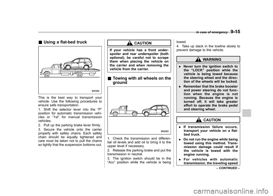
This is the best way to transport your
vehicle. Use the following procedures to
ensure safe transportation.
1. Shift the selector lever into the “P ”
position for automatic transmission vehi-
cles or “1st ”for manual transmission
vehicles.
2. Pull up the parking brake lever firmly.
3. Secure the vehicle onto the carrier
properly with safety chains. Each safety
chain should be equally tightened and
care must be taken not to pull the chains
so tightly that the suspension bottoms out.
CAUTION
If your vehicle has a front under-
spoiler and rear underspoiler (both
optional), be careful not to scrape
them when placing the vehicle on
the carrier and when removing the
vehicle from the carrier.
& Towing with all wheels on the ground
1. Check the transmission and differen-
tial oil levels and add oil to bring it to the
upper level if necessary.
2. Release the parking brake and put the
transmission in neutral.
3. The ignition switch should be in the “Acc ”position while the vehicle is being towed.
4. Take up slack in the towline slowly to
prevent damage to the vehicle.
WARNING
. Never turn the ignition switch to
the “LOCK ”position while the
vehicle is being towed because
the steering wheel and the direc-
tion of the wheels will be locked.
. Remember that the brake booster
and power steering do not func-
tion when the engine is not
running. Because the engine is
turned off, it will take greater
effort to operate the brake pedal
and steering wheel.
CAUTION
. If transmission failure occurs,
transport your vehicle on a flat-
bed truck.
. Do not run the engine while being
towed using this method. Trans-
mission damage could result if
the vehicle is towed with the
engine running.
. For vehicles with automatic
transmission, the traveling speed In case of emergency
9-15
– CONTINUED –
Page 296 of 384
Maintenance schedule....................................... 11-3
Maintenance precautions ................................... 11-3
Before checking or servicing in the engine compartment .................................................... 11-4
When you do checking or servicing in the engine compartment while the engine is running .......... 11-4
Engine hood ....................................................... 11-5
Engine compartment overview .......................... 11-6
Non-turbo models .............................................. 11-6
Turbo models ..................................................... 11-7
Engine oil ............................................................ 11-8
Checking the oil level ......................................... 11-8
Changing the oil and oil filter .............................. 11-9
Recommended grade and viscosity .................. 11-11
Recommended grade and viscosity under severe driving conditions .......................................... 11-12
Synthetic oil ..................................................... 11-12
Cooling system ................................................ 11-12
Cooling fan, hose and connections ................... 11-12
Engine coolant ................................................. 11-13
Air cleaner element .......................................... 11-15
Replacing the air cleaner element ..................... 11-16
Spark plugs ...................................................... 11-18
Recommended spark plugs .............................. 11-18
Drive belts ........................................................ 11-18
Manual transmission oil .................................. 11-19
Checking the oil level ....................................... 11-19
Recommended grade and viscosity .................. 11-20
Automatic transmission fluid .......................... 11-20
Checking the fluid level .................................... 11-20 Recommended fluid
......................................... 11-21
Front differential gear oil (AT vehicles) .......... 11-21
Checking the oil level ...................................... 11-21
Recommended grade and viscosity .................. 11-22
Rear differential gear oil .................................. 11-22
Checking the gear oil level ............................... 11-22
Recommended grade and viscosity .................. 11-23
Power steering fluid ........................................ 11-24
Checking the fluid level .................................... 11-24
Recommended fluid ......................................... 11-25
Brake fluid ........................................................ 11-25
Checking the fluid level .................................... 11-25
Recommended brake fluid ............................... 11-26
Clutch fluid (MT vehicles) ............................... 11-26
Checking the fluid level .................................... 11-26
Recommended clutch fluid ............................... 11-27
Brake booster .................................................. 11-27
Brake pedal ...................................................... 11-28
Checking the brake pedal free play .................. 11-28
Checking the brake pedal reserve distance....... 11-28
Clutch pedal (MT vehicles) .............................. 11-28
Checking the clutch function ............................ 11-28
Checking the clutch pedal free play .................. 11-29
Hill start assist system (MT vehicles) ............ 11-29
Replacement of brake pad and lining ............ 11-29
Breaking-in of new brake pads and linings ....... 11-30
Parking brake stroke ....................................... 11-30
Tires and wheels .............................................. 11-31
Types of tires ................................................... 11-31
Maintenance and service
11
Page 301 of 384
11-6Maintenance and service
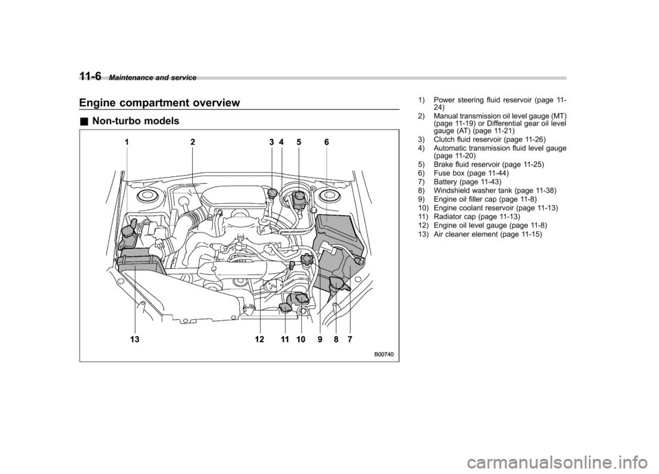
Engine compartment overview &Non-turbo models1) Power steering fluid reservoir (page 11-
24)
2) Manual transmission oil level gauge (MT) (page 11-19) or Differential gear oil level
gauge (AT) (page 11-21)
3) Clutch fluid reservoir (page 11-26)
4) Automatic transmission fluid level gauge (page 11-20)
5) Brake fluid reservoir (page 11-25)
6) Fuse box (page 11-44)
7) Battery (page 11-43)
8) Windshield washer tank (page 11-38)
9) Engine oil filler cap (page 11-8)
10) Engine coolant reservoir (page 11-13)
11) Radiator cap (page 11-13)
12) Engine oil level gauge (page 11-8)
13) Air cleaner element (page 11-15)
Page 302 of 384
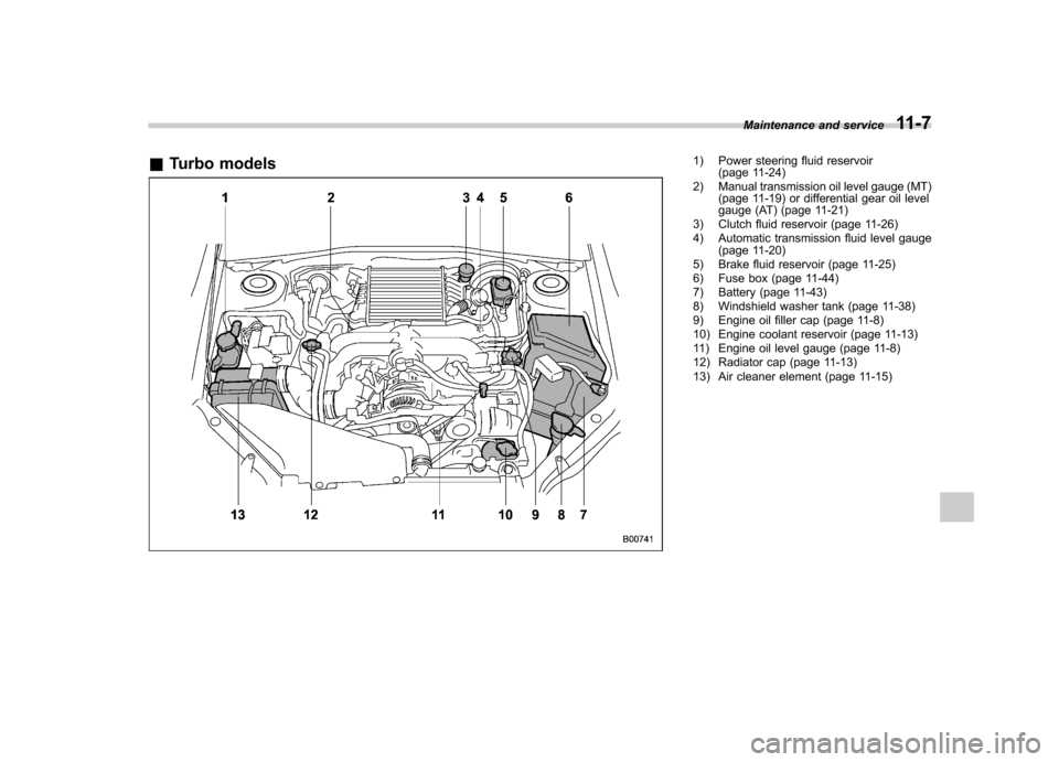
&Turbo models1) Power steering fluid reservoir
(page 11-24)
2) Manual transmission oil level gauge (MT) (page 11-19) or differential gear oil level
gauge (AT) (page 11-21)
3) Clutch fluid reservoir (page 11-26)
4) Automatic transmission fluid level gauge (page 11-20)
5) Brake fluid reservoir (page 11-25)
6) Fuse box (page 11-44)
7) Battery (page 11-43)
8) Windshield washer tank (page 11-38)
9) Engine oil filler cap (page 11-8)
10) Engine coolant reservoir (page 11-13)
11) Engine oil level gauge (page 11-8)
12) Radiator cap (page 11-13)
13) Air cleaner element (page 11-15) Maintenance and service
11-7