mirror SUBARU FORESTER 2010 SH / 3.G User Guide
[x] Cancel search | Manufacturer: SUBARU, Model Year: 2010, Model line: FORESTER, Model: SUBARU FORESTER 2010 SH / 3.GPages: 402, PDF Size: 14.36 MB
Page 151 of 402
3-40Instruments and controls
when the ignition switch is in the “ON ”or
“ Acc ”position.
1. Press either end of the selection switch, “L ” for the left, “R ”for the right.
2. Move the direction control switch in the
direction you want to move the mirror.
3. Return the selection switch to the
neutral position to prevent unintentionaloperation.
The mirrors can also be adjusted manu-
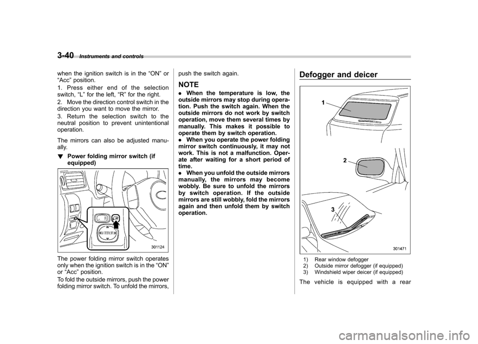
ally. ! Power folding mirror switch (if equipped)
The power folding mirror switch operates
only when the ignition switch is in the “ON ”
or “Acc ”position.
To fold the outside mirrors, push the power
folding mirror switch. To unfold the mirrors, push the switch again.
NOTE . When the temperature is low, the
outside mirrors may stop during opera-
tion. Push the switch again. When the
outside mirrors do not work by switch
operation, move them several times by
manually. This makes it possible to
operate them by switch operation.. When you operate the power folding
mirror switch continuously, it may not
work. This is not a malfunction. Oper-
ate after waiting for a short period oftime.. When you unfold the outside mirrors
manually, the mirrors may become
wobbly. Be sure to unfold the mirrors
by switch operation. If the outside
mirrors are still wobbly, fold the mirrors
again and then unfold them by switchoperation. Defogger and deicer1) Rear window defogger
2) Outside mirror defogger (if equipped)
3) Windshield wiper deicer (if equipped)
The vehicle is equipped with a rear
Page 152 of 402
window defogger. For some models, the
outside mirror defogger and/or windshield
wiper deicer are/is also equipped. The
defogger and deicer system is activated
only when the ignition switch is in the“ON ”
position.
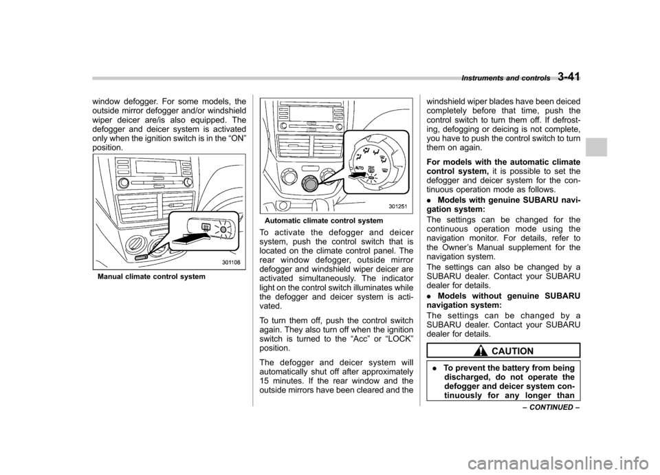
Manual climate control system
Automatic climate control system
To activate the defogger and deicer
system, push the control switch that is
located on the climate control panel. The
rear window defogger, outside mirror
defogger and windshield wiper deicer are
activated simultaneously. The indicator
light on the control switch illuminates while
the defogger and deicer system is acti-vated.
To turn them off, push the control switch
again. They also turn off when the ignition
switch is turned to the “Acc ”or “LOCK ”
position.
The defogger and deicer system will
automatically shut off after approximately
15 minutes. If the rear window and the
outside mirrors have been cleared and the windshield wiper blades have been deiced
completely before that time, push the
control switch to turn them off. If defrost-
ing, defogging or deicing is not complete,
you have to push the control switch to turn
them on again.
For models with the automatic climate
control system,
it is possible to set the
defogger and deicer system for the con-
tinuous operation mode as follows. . Models with genuine SUBARU navi-
gation system:
The settings can be changed for the
continuous operation mode using the
navigation monitor. For details, refer to
the Owner ’s Manual supplement for the
navigation system.
The settings can also be changed by a
SUBARU dealer. Contact your SUBARU
dealer for details. . Models without genuine SUBARU
navigation system:
The settings can be changed by a
SUBARU dealer. Contact your SUBARU
dealer for details.
CAUTION
. To prevent the battery from being
discharged, do not operate the
defogger and deicer system con-
tinuously for any longer than Instruments and controls
3-41
– CONTINUED –
Page 153 of 402
3-42Instruments and controls
necessary.
. Do not use sharp instruments or
window cleaner containing abra-
sives to clean the inner surface
of the rear window. They may
damage the conductors printed
on the window.
NOTE . Turn on the defogger and deicer
system if the wipers are frozen to the windshield.. If the windshield is covered with
snow, remove the snow so that the
windshield wiper deicer works effec-
tively.. While the defogger and deicer sys-
tem is in the continuous operation
mode, if the vehicle speed remains at
9 mph (15 km/h) or less for 15 minutes,
the windshield wiper deicer automati-
cally stops operating, though the rear
window defogger and outside mirror
defogger maintain continuous opera-
tion in this condition.. While the defogger and deicer sys-
tem is in the continuous operation
mode, if the battery voltage drops
below the permissible level, continu-
ous operation of the defogger and
deicer system is canceled and the system stops operating.
Tilt/telescopic steering wheel
WARNING
. Do not adjust the steering wheel
tilt/telescopic position while driv-
ing. This may cause loss of
vehicle control and result in
personal injury.
. If the lever cannot be raised to
the fixed position, adjust the
steering wheel again. It is dan-
gerous to drive without locking
the steering wheel. This may
cause loss of vehicle control
and result in personal injury.
Page 202 of 402
Interior lights....................................................... 6-2
Dome light .......................................................... 6-2
Cargo area light .................................................. 6-3
Map light ............................................................. 6-3
Sun visors ........................................................... 6-4
Vanity mirror ....................................................... 6-5
Storage compartment ......................................... 6-5
Glove box ........................................................... 6-5
Center console .................................................... 6-5
Overhead console ............................................... 6-7
Rear seat center table (if equipped) ..................... 6-7
Coin tray ............................................................. 6-7
Cup holders ......................................................... 6-8
Front passenger cup holder ................................. 6-8
Rear passenger cup holder (if equipped).. ............ 6-8Bottle holders
...................................................... 6-9
Accessory power outlets .................................... 6-9
Use with a cigarette lighter (dealer option)..... ..... 6-11
Ashtray (if equipped) ......................................... 6-11
Floor mat ............................................................ 6-12
Shopping bag hook ........................................... 6-12
Coat hook ........................................................... 6-13
Cargo area cover (dealer option) ...................... 6-13
Using the cover ................................................. 6-13
To remove the cover .......................................... 6-14
To install the cover housing ............................... 6-14
Cargo tie-down hooks ....................................... 6-15
Under-floor storage compartment (if equipped) .................................................... 6-16Interior equipment
6
Page 206 of 402
&Vanity mirror
CAUTION
Keep the vanity mirror cover closed
while the car is being driven to avoid
being temporarily blinded by the
glare of bright light.
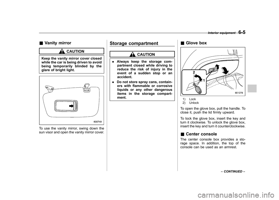
To use the vanity mirror, swing down the
sun visor and open the vanity mirror cover. Storage compartment
CAUTION
. Always keep the storage com-
partment closed while driving to
reduce the risk of injury in the
event of a sudden stop or anaccident.
. Do not store spray cans, contain-
ers with flammable or corrosive
liquids or any other dangerous
items in the storage compart-ment. &
Glove box
1) Lock
2) Unlock
To open the glove box, pull the handle. To
close it, push the lid firmly upward.
To lock the glove box, insert the key and
turn it clockwise. To unlock the glove box,
insert the key and turn it counterclockwise. & Center console
The center console box provides a sto-
rage space. In addition, the top of the
console can be used as an armrest. Interior equipment
6-5
– CONTINUED –
Page 224 of 402
trouble codes, and the OBD system
readiness monitors are complete. .A vehicle
fails the OBD inspection if the
“ CHECK ENGINE ”warning light/MIL is
not properly operating or there are one or
more diagnostic trouble codes stored in
the vehicle ’s computer with the “CHECK
ENGINE ”warning light/MIL illuminated.
. A state emission inspection may reject
(not pass or fail) a vehicle if the number of
OBD system readiness monitors “Not
Ready ”is greater than one. Under this
condition, the vehicle operator should be
instructed to drive his/her vehicle for a few
days to set the monitors and return for an
emission re-inspection. . Owners of rejected or failing vehicles
should contact their SUBARU Dealer for service. Preparing to drive
You should perform the following checks
and adjustments every day before you
start driving.
1. Check that all windows, mirrors, and
lights are clean and unobstructed.
2. Check the appearance and condition
of the tires. Also check tires for properinflation.
3. Look under the vehicle for any sign of leaks.
4. Check that the hood and rear gate are
fully closed.
5. Check the adjustment of the seat.
6. Check the adjustment of the inside
and outside mirrors.
7. Fasten your seatbelt. Check that your
passengers have fastened their seatbelts.
8. Check the operation of the warning
and indicator lights when the ignition
switch is turned to the
“ON ”position.
9. Check the gauges, indicator and warn-
ing lights after starting the engine.
NOTE
Engine oil, engine coolant, brake fluid,
washer fluid and other fluid levels
should be checked daily, weekly or at
fuel stops. Starting the engineCAUTION
Do not operate the starter motor
continuously for more than 10 sec-
onds. If the engine fails to start after
operating the starter for 5 to 10
seconds, wait for 10 seconds or
more before trying again.
& Manual transmission model
1. Apply the parking brake.
2. Turn off unnecessary lights and ac- cessories.
3. Press the clutch pedal to the floor and
shift the shift lever into neutral. Hold the
clutch pedal to the floor while starting theengine.
The starter motor will only operate when
the clutch pedal is pressed fully to the
floor.
4. Turn the ignition switch to the “ON ”
position and check the operation of the
warning and indicator lights. Refer to“ Warning and indicator lights ”F 3-9.
5. Turn the ignition switch to the “START ”
position without depressing the accelera-
tor pedal. Release the key immediately
after the engine has started. Starting and operating
7-7
– CONTINUED –
Page 277 of 402
8-22Driving tips
&Connecting a trailer
! Trailer brakes
WARNING
. Adequate size trailer brakes are
required when the trailer and its
cargo exceed 1,000 lbs (453 kg)
total weight.
. Do not directly connect your
trailer ’s hydraulic brake system
to the hydraulic brake system in
your vehicle. Direct connection
would cause the vehicle ’s brake
performance to deteriorate and
could lead to an accident.
If your trailer ’s total weight (trailer weight
plus its cargo weight) exceeds 1,000 lbs
(453 kg), the trailer is required to be
equipped with its own brake system.
Electric brakes or surge brakes are
recommended, and must be installed
properly. Check that your trailer ’s brakes
conform with Federal, state/province and/
or other applicable regulations. YourSUBARU ’s brake system is not designed
to be tapped into the trailer ’s hydraulic
brake system. Please ask your SUBARU
dealer and professional trailer supplier for
more information about the trailer ’s brake
system. !
Trailer safety chains
WARNING
Always use safety chains between
your vehicle and the trailer. Towing a
trailer without safety chains could
create a traffic safety hazard if the
trailer separates from the hitch due
to coupling damage or hitch balldamage.
In case the trailer hitch connector or hitch
ball should break or become discon-
nected, the trailer could get loose and
create a traffic safety hazard.
For safety, always connect the towing
vehicle and trailer with trailer safety
chains. Pass the chains crossing each
other under the trailer tongue to prevent
the trailer from dropping onto the ground
in case the trailer tongue should discon-
nect from the hitch ball. Allow sufficient
slack in the chains taking tight-turn situa-
tions into account; however, be careful not
to let them drag on the ground.
For more information about the safety
chain connection, refer to the instructions
for your hitch and trailer. !
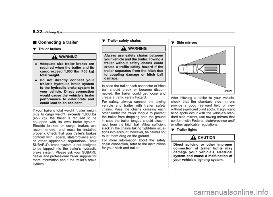
Side mirrors
After hitching a trailer to your vehicle,
check that the standard side mirrors
provide a good rearward field of view
without significant blind spots. If significant
blind spots occur with the vehicle ’s stan-
dard side mirrors, use towing mirrors that
conform with Federal, state/province and/
or other applicable regulations. ! Trailer lights
CAUTION
Direct splicing or other improper
connection of trailer lights may
damage your vehicle ’s electrical
system and cause a malfunction of
your vehicle ’s lighting system.
Page 278 of 402
Connection of trailer lights to your vehi- cle’s electrical system requires modifica-
tions to the vehicle ’s lighting circuit to
increase its capacity and accommodate
wiring changes. To ensure the trailer lights
are connected properly, please consult
your SUBARU dealer. Check for proper
operation of the brake lights and turn
signal lights each time you hitch up. ! Tires
WARNING
Never tow a trailer when the tem-
porary spare tire is used. The tem-
porary spare tire is not designed to
sustain the towing load. Use of the
temporary spare tire when towing
can result in failure of the spare tire
and/or less stability of the vehicle.
Make sure that all the tires on your vehicle
are properly inflated.
The recommended cold tire pressure
under trailer towing conditions is shownin “Tires ”F 12-5 and in “GAS STATION
REFERENCE ”at the end of this manual.
Adjust the rear tire pressure to the
recommended pressure when the tires
are cold. Normal pressure should be
maintained in the front tires. Trailer tire condition, size, load rating and
proper inflation pressure should be in
accordance with the trailer manufacturer
’s
specifications.
In the event your vehicle gets a flat tire
when towing a trailer, ask a commercial
road service to repair the flat tire.
If you carry a regular size spare tire in your
vehicle or trailer as a precaution against
getting a flat tire, be sure that the spare
tire is firmly secured.
& Trailer towing tips
WARNING
. Never exceed 45 mph (72 km/h)
when towing a trailer in hilly
country on hot days.
. When towing a trailer, steering,
stability, stopping distance and
braking performance will be dif-
ferent from normal operation. Forsafety ’s sake, you should employ
extracautionwhentowinga
trailer and you should never
speed. You should also keep the
following tips in mind: !
Before starting out on a trip
. Check that the vehicle and vehicle-to-
hitch mounting are in good condition. If
any problems are apparent, do not tow the
trailer. . Check that the vehicle sits horizontally
with the trailer attached. If the vehicle is
tipped sharply up at the front and down at
the rear, check the total trailer weight,
GVW, GAWs and tongue load again, then
confirm that the load and its distribution
are acceptable. . Check that the tire pressures are
correct.. Check that the vehicle and trailer are
connected properly. Confirm that
–the trailer tongue is connected
properly to the hitch ball. – the trailer lights connector is con-
nected properly and trailer ’sbrake
lights illuminate when the vehicle ’s
brake pedal is pressed, and that the trailer ’s turn signal lights flash when
the vehicle ’s turn signal lever is oper-
ated. – the safety chains are connected
properly.– all cargo in the trailer is secured
safety in position.– the side mirrors provide a good
rearward field of view without a sig- Driving tips
8-23
– CONTINUED –
Page 363 of 402
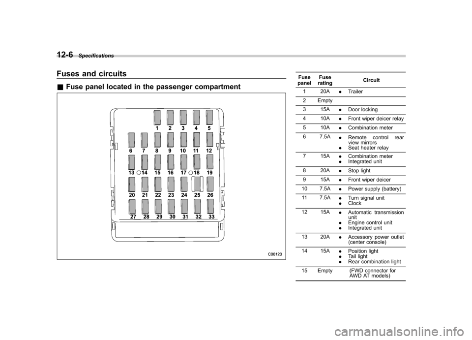
12-6Specifications
Fuses and circuits &Fuse panel located in the passenger compartmentFuse
panel Fuse
rating Circuit
1 20A .Trailer
2 Empty
3 15A .Door locking
4 10A .Front wiper deicer relay
5 10A .Combination meter
6 7.5A .Remote control rear
view mirrors
. Seat heater relay
7 15A .Combination meter
. Integrated unit
8 20A .Stop light
9 15A .Front wiper deicer
10 7.5A .Power supply (battery)
11 7.5A .Turn signal unit
. Clock
12 15A .Automatic transmission
unit
. Engine control unit
. Integrated unit
13 20A .Accessory power outlet
(center console)
14 15A .Position light
. Tail light
. Rear combination light
15 Empty (FWD connector for AWD AT models)
Page 365 of 402
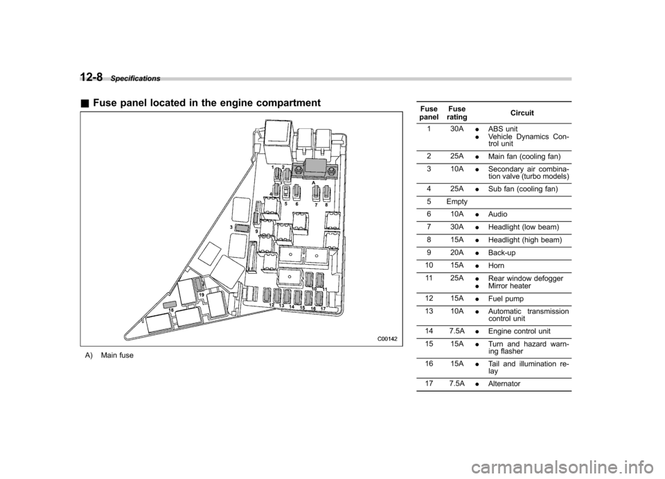
12-8Specifications
&Fuse panel located in the engine compartment
A) Main fuse Fuse
panel Fuse
rating Circuit
1 30A .ABS unit
. Vehicle Dynamics Con-
trol unit
2 25A .Main fan (cooling fan)
3 10A .Secondary air combina-
tion valve (turbo models)
4 25A .Sub fan (cooling fan)
5 Empty
6 10A .Audio
7 30A .Headlight (low beam)
8 15A .Headlight (high beam)
9 20A .Back-up
10 15A .Horn
11 25A .Rear window defogger
. Mirror heater
12 15A .Fuel pump
13 10A .Automatic transmission
control unit
14 7.5A .Engine control unit
15 15A .Turn and hazard warn-
ing flasher
16 15A .Tail and illumination re-
lay
17 7.5A .Alternator