sensor SUBARU FORESTER 2010 SH / 3.G User Guide
[x] Cancel search | Manufacturer: SUBARU, Model Year: 2010, Model line: FORESTER, Model: SUBARU FORESTER 2010 SH / 3.GPages: 402, PDF Size: 14.36 MB
Page 86 of 402
Keys..................................................................... 2-2
Key number plate ................................................ 2-2
Immobilizer .......................................................... 2-2
Security ID plate .................................................. 2-3
Security indicator light ........................................ 2-3
Key replacement ................................................. 2-4
Door locks ........................................................... 2-4
Locking and unlocking from the outside .. ............ 2-4
Locking and unlocking from the inside ................ 2-5
Battery drainage prevention function ................... 2-5
Power door locking switches ............................. 2-6
Key lock-in prevention function ........................... 2-7
Remote keyless entry system ............................ 2-7
Locking the doors ............................................... 2-8
Unlocking the doors ............................................ 2-9
Unlocking the rear gate ....................................... 2-9
Illuminated entry ................................................. 2-9
Vehicle finder function ......................................... 2-9
Sounding a panic alarm ...................................... 2-10
Selecting audible signal operation ...................... 2-10
Replacing the battery ......................................... 2-10 Replacing lost transmitters
................................ 2-11
Alarm system ..................................................... 2-14
System operation ............................................... 2-14
Activating and deactivating the alarm system ..... 2-15
If you have accidentally triggered the alarm system ............................................................ 2-15
Arming the system ............................................ 2-15
Disarming the system ........................................ 2-17
Valet mode ........................................................ 2-17
Passive arming .................................................. 2-17
Tripped sensor identification .............................. 2-18
Shock sensors (dealer option).. .......................... 2-19
Child safety locks .............................................. 2-19
Windows ............................................................. 2-20
Power windows ................................................. 2-20
Rear gate ............................................................ 2-22
Moonroof (if equipped) ...................................... 2-23
To open the moonroof ....................................... 2-24
To close the moonroof ....................................... 2-24
Anti-entrapment function .................................... 2-24
Sun shade ......................................................... 2-25 Keys and doors
2
Page 89 of 402

2-4Keys and doors
for surveillance (Refer to “Arming the
system ”F 2-15.)
. Other flashing patterns:
The alarm system may have been trig-
gered by unauthorized intrusion or any
impact to the vehicle body. Refer to“ Tripped sensor identification ”F 2-18.
If the security indicator light does not flash,
the immobilizer system may be faulty. If
this occurs, contact your SUBARU dealer
as soon as possible.
In case an unauthorized key is used (e.g.
an imitation key), the security indicator
light illuminates.
NOTE
Even if the security indicator light
flashes irregularly or its fuse blows
(the light does not flash if its fuse is
blown), the immobilizer system will
function normally. & Key replacement
Your key number plate and security ID
plate will be required if you ever need a
replacement key made. Any new key must
be registered for use with your vehicle ’s
immobilizer system before it can be used.
Up to four keys can be registered for use
with one vehicle. For security, all the keys registered with
your vehicle
’s immobilizer system will
have their ID codes erased and re-
registered when a new key is made.
Therefore, all of your vehicle ’s keys must
be presented when a new key is regis-
tered. Any key that is not re-registered
when a new key is made cannot be used
after the other keys are re-registered. For
information on replacement keys and on
the registration of keys with your immo-
bilizer system, contact your SUBARU
dealer.
NOTE
A vehicle that is equipped with the
remote engine start system as a dealer
option can register up to three keys for
use with one vehicle. Door locks &
Locking and unlocking from
the outside
To lock the driver ’s door from the outside
with the key, turn the key toward the rear.
To unlock the door, turn the key toward thefront.
Pull the outside door handle to open an
unlocked door.
Page 100 of 402

closed while the horn is sounding, the
horn will stop sounding with a delay of up
to 30 seconds.
The alarm is triggered by: .Opening any of the doors or the rear
gate. Physical impact to the vehicle, such as
forced entry (only vehicles with shock
sensors (dealer option)) NOTE
The alarm system can be set to trigger
the illumination of the following interiorlights. . Dome light (illuminates only when
the dome light switch is in the “DOOR ”
position) . Map lights (illuminate only when the
door interlock switch is in the “DOOR ”
position)
The notifications regarding the dome
light and the map lights are deactivated
as the factory setting. A SUBARU
dealer can activate the system. Contact
your SUBARU dealer for details. &
Activating and deactivating
the alarm system
To change the setting of your vehicle ’s
alarm system for activation or deactiva-
tion, do the following.
1. Disarm the alarm system. Refer to “ Disarming the system ”F 2-17.
2. Sit in the driver ’s seat and shut all
doors and the rear gate.
3. Turn the ignition switch to the “ON ”
position.
4. Hold down the UNLOCK side of the driver ’s power door locking switch, open
the driver ’s door within the following 1
second, and wait 10 seconds without
releasing the switch. The setting will then
be changed as follows.
If the system was previously activated:
The odometer/trip meter screen displays “ AL oF ”and the horn sounds twice,
indicating that the system is now deacti-vated.
If the system was previously deacti- vated:
The odometer/trip meter screen displays “ AL on ”and the horn sounds once,
indicating that the system is now acti-vated. NOTE
You may have the above setting
change done by your SUBARU dealer. &
If you have accidentally trig-
gered the alarm system
! To stop the alarm
Do any of the following operations: . Press any button on the remote trans-
mitter.. Turn the ignition switch to the “ON ”
position. & Arming the system
! To arm the system using remote transmitter
1. Close all windows and the moonroof (ifequipped).
2. Remove the key from the ignition switch.
3. Open the doors and get out of the vehicle.
4. Make sure that the engine hood is locked.
5. Close all doors and the rear gate. Keys and doors
2-15
– CONTINUED –
Page 103 of 402
2-18Keys and doors
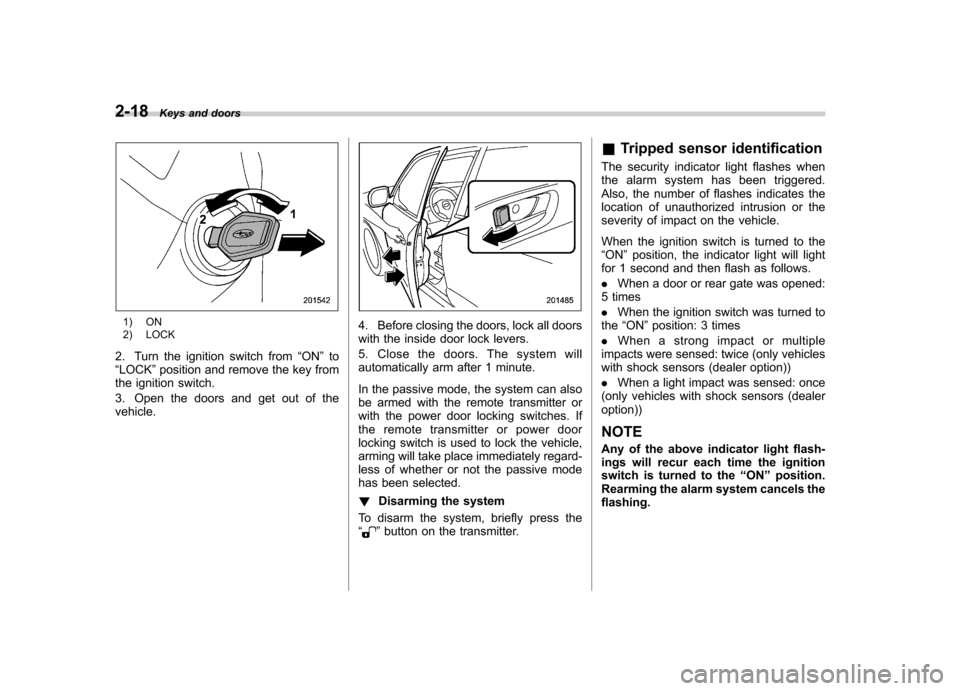
1) ON
2) LOCK
2. Turn the ignition switch from “ON ”to
“ LOCK ”position and remove the key from
the ignition switch.
3. Open the doors and get out of the vehicle.4. Before closing the doors, lock all doors
with the inside door lock levers.
5. Close the doors. The system will
automatically arm after 1 minute.
In the passive mode, the system can also
be armed with the remote transmitter or
with the power door locking switches. If
the remote transmitter or power door
locking switch is used to lock the vehicle,
arming will take place immediately regard-
less of whether or not the passive mode
has been selected. ! Disarming the system
To disarm the system, briefly press the “
” button on the transmitter. &
Tripped sensor identification
The security indicator light flashes when
the alarm system has been triggered.
Also, the number of flashes indicates the
location of unauthorized intrusion or the
severity of impact on the vehicle.
When the ignition switch is turned to the “ ON ”position, the indicator light will light
for 1 second and then flash as follows. . When a door or rear gate was opened:
5 times. When the ignition switch was turned to
the “ON ”position: 3 times
. When a strong impact or multiple
impacts were sensed: twice (only vehicles
with shock sensors (dealer option)) . When a light impact was sensed: once
(only vehicles with shock sensors (dealer option))
NOTE
Any of the above indicator light flash-
ings will recur each time the ignition
switch is turned to the “ON ”position.
Rearming the alarm system cancels the flashing.
Page 104 of 402
&Shock sensors (dealer op- tion)
The shock sensors trigger the alarm
system when they sense impacts applied
to the vehicle and when any of their
electric wires are cut. The alarm system
causes the horn to sound and the turn
signal lights to flash for a short time when
the sensed impact is weak, but it warns of
a strong impact or multiple impacts by
sounding the horn and flashing the turn
signal lights, both lasting approximately 30seconds.
If you desire, your SUBARU dealer can
connect them and set them for activation
or deactivation. NOTE . The shock sensors are not always
able to sense impacts caused by break-
ing in, and cannot sense an impact that
does not cause vibration (such as
breaking the glass using a rescuehammer).. The shock sensors may sense vi-
bration as indicated in the following
examples and trigger the alarm system.
Select the settings of the alarm system
and shock sensors appropriately de-
pending on where you usually park
your vehicle. Examples:
Vibration from a construction site
Vibration in a multistory car park
Vibration from trains
. You can have the sensitivity of the
shock sensors adjusted to your pre-
ference by your SUBARU dealer. Child safety locks
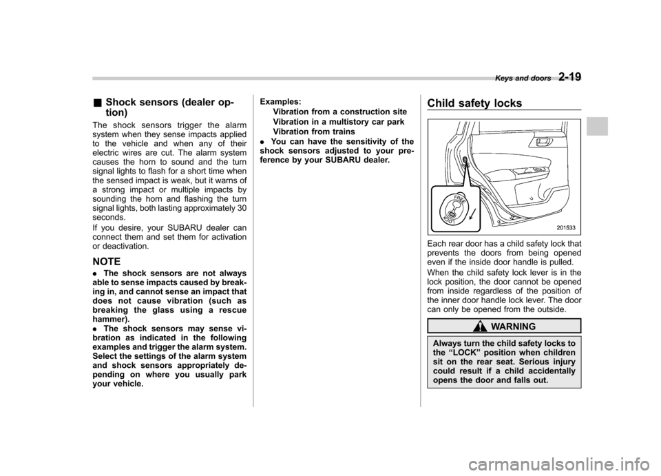
Each rear door has a child safety lock that
prevents the doors from being opened
even if the inside door handle is pulled.
When the child safety lock lever is in the
lock position, the door cannot be opened
from inside regardless of the position of
the inner door handle lock lever. The door
can only be opened from the outside.
WARNING
Always turn the child safety locks to the “LOCK ”position when children
sit on the rear seat. Serious injury
could result if a child accidentally
opens the door and falls out. Keys and doors
2-19
Page 127 of 402
3-16Instruments and controls
the tire to lose air rapidly. If you have
a flat tire, replace it with a spare tire
as soon as possible.
When a spare tire is mounted or a
wheel rim is replaced without the
original pressure sensor/transmitter
being transferred, the Low tire pres-
sure warning light will illuminate
steadily after blinking for approxi-
mately one minute. This indicates
the TPMS is unable to monitor all
four road wheels. Contact your
SUBARU dealer as soon as possible
for tire and sensor replacement and/
or system resetting. If the light
illuminates steadily after blinking
for approximately one minute,
promptly contact a SUBARU dealer
to have the system inspected.
CAUTION
The tire pressure monitoring system
is NOT a substitute for manually
checking tire pressure. The tire
pressure should be checked peri-
odically (at least monthly) using a
tire gauge. After any change to tire
pressure(s), the tire pressure mon-
itoring system will not re-check tire
inflation pressures until the vehicle
is first driven more than 20 mph (32 km/h). After adjusting the tire pres-
sures, increase the vehicle speed to
at least 20 mph (32 km/h) to start the
TPMS re-checking of the tire infla-
tion pressures. If the tire pressures
are now above the severe low
pressure threshold, the low tire
pressure warning light should turn
off a few minutes later. Therefore, be
sure to install the specified size for
the front and rear tires.
& ABS warning light
The ABS warning light illuminates when
the ignition switch is turned to the “ON ”
position and turns off after approximately 2seconds.
This is an indication that the ABS system
is working properly.
CAUTION
If the warning light behaves as
follows, the ABS system may not
work properly.
When the warning light is on, the
ABS function shuts down; however,
the conventional brake system con-
tinues to operate normally. . The warning light does not illu-
minate when the ignition switch is turned to the
“ON ”position.
. The warning light illuminates
when the ignition switch is
turned to the “ON ”position, but
it does not turn off even when the
vehicle speed exceeds approxi-
mately 8 mph (12 km/h).
. The warning light illuminates dur-
ing driving.
If any of these conditions occur,
have the ABS system repaired at
the first available opportunity by
your SUBARU dealer.
With a vehicle equipped with an EBD
system, the ABS warning light illuminates
together with the brake system warning
light if the EBD system becomes faulty.
For further details of the EBD system fault
warning, refer to “Brake system warning
light ”F 3-17.
NOTE
If the warning light behavior is as
described in the following, the ABS
system may be considered normal. . The warning light illuminates right
after the engine is started but turns off
immediately, remaining off.. The warning light remains on after
the engine has been started, but it
turns off when the vehicle speed
Page 143 of 402
3-32Instruments and controls
speed is high).
When the transmission is shifted into
reverse, the rear wiper will switch to
continuous operation. When the transmis-
sion is shifted to a position other than
reverse, the rear wiper will return to
intermittent operation. !Washer
To wash the rear window while the rear
wiper is operating, turn the knob clockwise
to the “
”position. The washer fluid
sprays until you release the knob.
To wash the rear window when the rear
wiper is not in use, turn the knob counter-
clockwise to the “
”position. The washer
fluid sprays, and 2 seconds later the rear
wiper operates. Releasing the knob stops
the washer fluid spray, and 3 seconds
later the rear wiper stops. Mirrors
Always check that the inside and outside
mirrors are properly adjusted before you
start driving. &
Inside mirror
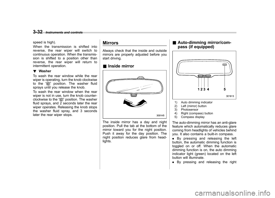
The inside mirror has a day and night
position. Pull the tab at the bottom of the
mirror toward you for the night position.
Push it away for the day position. The
night position reduces glare from head-lights. &
Auto-dimming mirror/com-
pass (if equipped)
1) Auto dimming indicator
2) Left (mirror) button
3) Photosensor
4) Right (compass) button
5) Compass display
The auto-dimming mirror has an anti-glare
feature which automatically reduces glare
coming from headlights of vehicles behind
you. It also contains a built-in compass. . By pressing and releasing the left
button, the automatic dimming function is
toggled on or off. When the automatic
dimming function is on, the auto dimming
indicator light (green) located on the left
button will illuminate. . By pressing and releasing the right
Page 144 of 402
button, the compass display is toggled on
or off. When the compass is on, an
illuminated compass reading will appear
in the upper right corner of the mirror.
Even with the mirror in anti-glare mode,
the mirror surface turns bright if the
transmission is shifted into reverse. This
is to ensure good rearward visibility duringreversing. !Photosensors
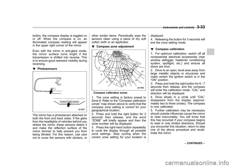
The mirror has a photosensor attached on
both the front and back sides. If the glare
from the headlights of vehicles behind you
strikes the mirror, these sensors detect it
and make the reflection surface of the
mirror dimmer to help prevent you from
being blinded. For this reason, use care
not to cover the sensors with stickers, or other similar items. Periodically wipe the
sensors clean using a piece of dry soft
cotton cloth or an applicator. !
Compass zone adjustment
Compass calibration zones
1. The zone setting is factory preset to
Zone 8. Refer to the “Compass calibration
zones ”map shown above to verify that the
compass zone setting is correct for your
geographical location.
2. Press and hold the right button for 3
seconds then release, and the word“ ZONE ”will briefly appear and then the
zone number will be displayed.
3. Press the right-hand button repeatedly
to cycle the display through all possible
zone settings. Stop cycling when the
correct zone setting for your location is displayed.
4. Releasing the button for 3 seconds will
exit the zone setting mode. !
Compass calibration
1. For optimum calibration, switch off all
nonessential electrical accessories (rear
window defogger, heater/air conditioning
system, spotlight, etc.) and ensure all
doors are shut.
2. Drive to an open, level area away from
large metallic objects or structures and
make certain the ignition switch is in the“ ON ”position.
3. Press and hold the right button for 6 - 7
seconds then release, and the compass
will enter the calibration mode. “CAL ”and
direction will be displayed.
4. Drive slowly in a circle until “CAL ”
disappears from the display (approxi-
mately two to three circles). The compass
is now calibrated.
5. Further calibration may be necessary
should outside influences cause the mirror
to read inaccurately. You will know that
this has occurred if your compass begins
to read in only limited directions. Should
you encounter this situation, return to step
one of the above procedure and recali-
brate the mirror. Instruments and controls
3-33
– CONTINUED –
Page 145 of 402
3-34Instruments and controls
& Auto-dimming mirror/com-
pass with HomeLink
®(if
equipped)
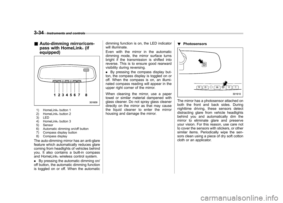
1) HomeLink®button 1
2) HomeLink®button 2
3) LED
4) HomeLink
®button 3
5) Sensor
6) Automatic dimming on/off button
7) Compass display button
8) Compass display
The auto-dimming mirror has an anti-glare
feature which automatically reduces glare
coming from headlights of vehicles behind
you. It also contains a built-in compass
and HomeLink
®wireless control system.
. By pressing the automatic dimming on/
off button, the automatic dimming function
is toggled on or off. When the automatic dimming function is on, the LED indicator
will illuminate.
Even with the mirror in the automatic
dimming mode, the mirror surface turns
bright if the transmission is shifted into
reverse. This is to ensure good rearward
visibility during reversing. .
By pressing the compass display but-
ton, the compass display is toggled on or
off. When the compass is on, an illumi-
nated compass reading will appear in the
upper right corner of the mirror.
When cleaning the mirror, use a paper
towel or similar material dampened with
glass cleaner. Do not spray glass cleaner
directly on the mirror as that may cause
the liquid cleaner to enter the mirror
housing and damage the mirror. !
Photosensors
The mirror has a photosensor attached on
both the front and back sides. During
nighttime driving, these sensors detect
distracting glare from vehicle headlights
behind you and automatically dim the
mirror to eliminate glare and preserve
your vision. For this reason, use care not
to cover the sensors with stickers, or other
similar items. Periodically wipe the sen-
sors clean using a piece of dry soft cotton
cloth or an applicator.
Page 156 of 402
Ventilator.............................................................. 4-2
Airflow selection ................................................. 4-2
Center and side ventilators .................................. 4-3
Manual climate control system (if equipped) ..................................................... 4-3
Control panel ...................................................... 4-3
Heater operation ................................................. 4-5
Air conditioner operation ..................................... 4-7
Automatic climate control system (if equipped) ..................................................... 4-8
Control panel ...................................................... 4-8
To use as full-automatic climate control system .............................................................. 4-8
To use as semi-automatic climate control system .............................................................. 4-8
Fan speed control dial ......................................... 4-9
Temperature control dial ...................................... 4-9
Airflow control dial .............................................. 4-9
Air inlet selection button .................................... 4-10 Air conditioner button
........................................ 4-10
Temperature sensors ......................................... 4-11
Operating tips for heater and air conditioner ...................................................... 4-12
Cleaning ventilation grille ................................... 4-12
Efficient cooling after parking in direct sunlight ........................................................... 4-12
Lubrication oil circulation in the refrigerant circuit ............................................................. 4-12
Checking air conditioning system before summer season ............................................... 4-12
Cooling and dehumidifying in high humidity and low temperature weather conditions ................. 4-12
Air conditioner compressor shut-off when engine is heavily loaded .............................................. 4-12
Refrigerant for your climate control system ... ..... 4-12
Air filtration system ........................................... 4-13
Replacing an air filter ......................................... 4-13Climate control
4