wheel SUBARU FORESTER 2010 SH / 3.G User Guide
[x] Cancel search | Manufacturer: SUBARU, Model Year: 2010, Model line: FORESTER, Model: SUBARU FORESTER 2010 SH / 3.GPages: 402, PDF Size: 14.36 MB
Page 68 of 402

books, shoes, or other objects trapped
under the seat, at the rear of the seat, or
on the side of the seat. .Ensure that the backward-forward po-
sition and seatback of front passenger ’s
seat are locked into place securely by
moving the seat back and forth. . Next, turn the ignition switch to the
“ ON ”position and wait 6 seconds to allow
the system to complete self-checking.
Following the system check, both indica-
tors turn off for 2 seconds. Now, the ON
indicator should illuminate while the OFF
indicator remains off.
If the OFF indicator still remains illumi-
nated while the ON indicator remains off,
ask the occupant to move to the rear seat
and immediately contact your SUBARU
dealer for an inspection. ! Effect vehicle modifications made
for persons with disabilities may
have on SUBARU advanced frontal
airbag system operation (U.S. only)
Changing or moving any parts of the front
seats, rear seat, seatbelts, front bumper,
front side frame, radiator panel, instrument
panel, combination meter, steering wheel,
steering column, tire, suspension or floor
panel can affect the operation of the
SUBARU advanced airbag system. If
you have any questions, you may contact the following SUBARU distributors.
Subaru of America, Inc.
Customer Dealer Services Department
P.O. Box 6000
Cherry Hill, NJ 08034-6000
1-800-SUBARU3 (1-800-782-2783)
Servco Subaru Inc., dba Subaru Hawaii
2850 Pukoloa Street, Suite 202, Honolulu,
HI 96819 808-839-2273
’s Corporation dba Prestige Automo-
bile
491, East Marine Drive, Route 1 Dededo, Guam 671-633-2698
Trebol Motors
P.O. Box 11204, San Juan, Puerto Rico 00910 787-793-2828
There are currently no SUBARU distribu-
tors in any other U.S. territories. If you are
in such an area, please contact the
SUBARU distributor or dealer from which you bought your vehicle.
Seat, seatbelt and SRS airbags
1-45
– CONTINUED –
Page 70 of 402

The two inflators of each airbag are
triggered either sequentially or simulta-
neously, depending on the severity of
impact, in the case of the driver’s SRS
frontal airbag and depending on the
severity of impact and the total load on
the seat in the case of the front passen-ger ’s SRS frontal airbag. After deploy-
ment, the SRS airbag immediately starts
to deflate so that the driver ’s vision is not
obstructed. The time required from detect-
ing impact to the deflation of the SRS
airbag after deployment is shorter than the
blink of an eye.
Both when only the driver ’s SRS frontal
airbag deploys and the driver ’s and front
passenger ’s SRS frontal airbags deploy,
the driver ’s and front passenger ’s seatbelt
pretensioners operate at the same time.
Although it is highly unlikely that the SRS
airbag would activate in a non-accident
situation, should it occur, the SRS airbag
will deflate quickly, not obscuring vision
and will not interfere with the driver ’s
ability to maintain control of the vehicle.
When the SRS airbag deploys, a sudden,
fairly loud inflation noise will be heard and
some smoke will be released. These
occurrences are a normal result of the
deployment. This smoke does not indicate
a fire in the vehicle.CAUTION
Do not touch the SRS airbag system
components around the steering
wheel and dashboard with bare
hands right after deployment. Doing
so can cause burns because the
components can be very hot as a
result of deployment.
The driver ’s SRS frontal airbag and front
passenger ’s SRS frontal airbag are de-
signed to deploy in the event of an
accident involving a moderate to severe
frontal collision. It is basically not designed
to deploy in lesser frontal impacts be-
cause the necessary protection can be
achieved by the seatbelt alone. Also, they
are basically not designed to deploy in
side or rear impacts or in roll-over acci-
dents because deployment of only thedriver ’s SRS frontal airbag or both driver ’s
and front passenger ’s SRS frontal airbags
would not help the occupant in those
situations. The driver ’s and front passen-
ger ’s SRS frontal airbags are designed to
function on a one-time-only basis.
SRS airbag deployment depends on the
level of force experienced in the passen-
ger compartment during a collision. That
level differs from one type of collision to
another, and it may have no bearing on the visible damage done to the vehicleitself. !
Example of accident in which the driver ’s/driver ’s and front passen-
ger ’s SRS frontal airbag(s) will most
likely deploy.
A head-on collision against a thick con-
crete wall at a vehicle speed of 12 to 19
mph (20 to 30 km/h) or higher activates
only the driver ’s SRS frontal airbag or both
driver ’s and front passenger ’s SRS frontal
airbags. The airbag(s) will also be acti-
vated when the vehicle is exposed to a
frontal impact similar in fashion and
magnitude to the collision describedabove. Seat, seatbelt and SRS airbags
1-47
– CONTINUED –
Page 76 of 402
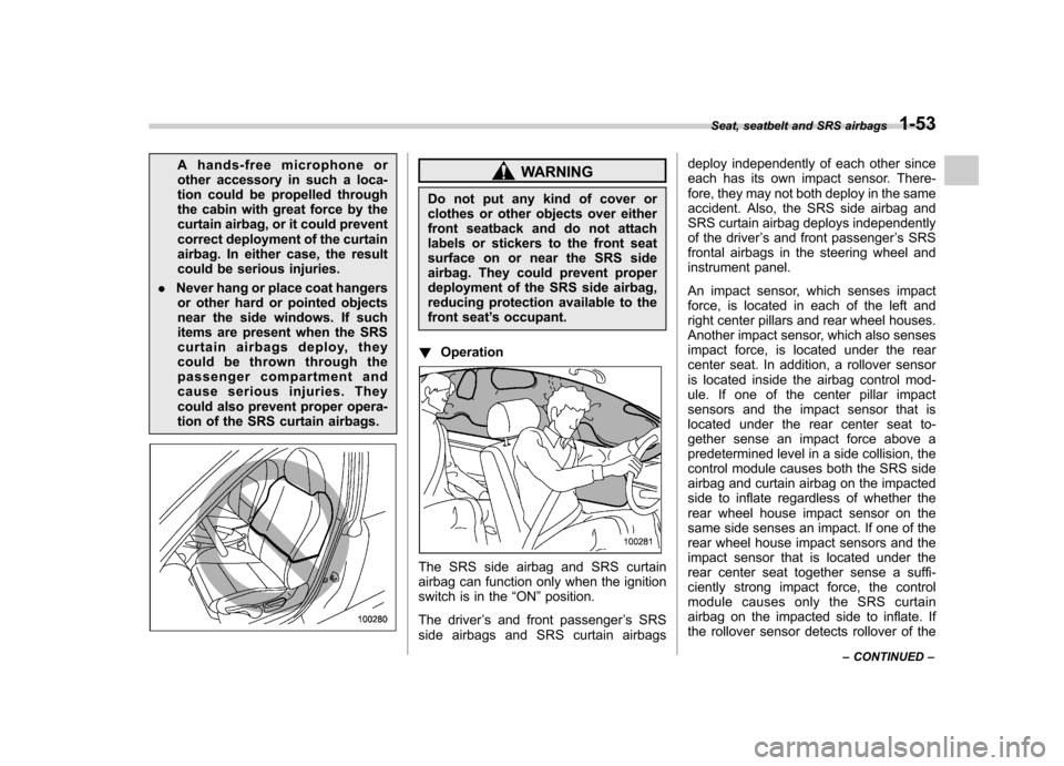
A hands-free microphone or
other accessory in such a loca-
tion could be propelled through
the cabin with great force by the
curtain airbag, or it could prevent
correct deployment of the curtain
airbag. In either case, the result
could be serious injuries.
. Never hang or place coat hangers
or other hard or pointed objects
near the side windows. If such
items are present when the SRS
curtain airbags deploy, they
could be thrown through the
passenger compartment and
cause serious injuries. They
could also prevent proper opera-
tion of the SRS curtain airbags.WARNING
Do not put any kind of cover or
clothes or other objects over either
front seatback and do not attach
labels or stickers to the front seat
surface on or near the SRS side
airbag. They could prevent proper
deployment of the SRS side airbag,
reducing protection available to the
front seat ’s occupant.
! Operation
The SRS side airbag and SRS curtain
airbag can function only when the ignition
switch is in the “ON ”position.
The driver ’s and front passenger ’s SRS
side airbags and SRS curtain airbags deploy independently of each other since
each has its own impact sensor. There-
fore, they may not both deploy in the same
accident. Also, the SRS side airbag and
SRS curtain airbag deploys independently
of the driver
’s and front passenger ’s SRS
frontal airbags in the steering wheel and
instrument panel.
An impact sensor, which senses impact
force, is located in each of the left and
right center pillars and rear wheel houses.
Another impact sensor, which also senses
impact force, is located under the rear
center seat. In addition, a rollover sensor
is located inside the airbag control mod-
ule. If one of the center pillar impact
sensors and the impact sensor that is
located under the rear center seat to-
gether sense an impact force above a
predetermined level in a side collision, the
control module causes both the SRS side
airbag and curtain airbag on the impacted
side to inflate regardless of whether the
rear wheel house impact sensor on the
same side senses an impact. If one of the
rear wheel house impact sensors and the
impact sensor that is located under the
rear center seat together sense a suffi-
ciently strong impact force, the control
module causes only the SRS curtain
airbag on the impacted side to inflate. If
the rollover sensor detects rollover of the Seat, seatbelt and SRS airbags
1-53
– CONTINUED –
Page 83 of 402
1-60Seat, seatbelt and SRS airbags
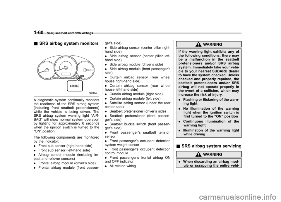
&SRS airbag system monitors
A diagnostic system continually monitors
the readiness of the SRS airbag system
(including front seatbelt pretensioners)
while the vehicle is being driven. The
SRS airbag system warning light “AIR-
BAG ”will show normal system operation
by lighting for approximately 6 seconds
when the ignition switch is turned to the“ ON ”position.
The following components are monitored
by the indicator: . Front sub sensor (right-hand side)
. Front sub sensor (left-hand side)
. Airbag control module (including im-
pact and rollover sensors). Frontal airbag module (driver ’s side)
. Frontal airbag module (front passen- ger
’s side)
. Side airbag sensor (center pillar right-
hand side). Side airbag sensor (center pillar left-
hand side). Side airbag module (driver ’s side)
. Side airbag module (front passenger ’s
side). Curtain airbag sensor (rear wheel
house right-hand side). Curtain airbag sensor (rear wheel
house left-hand side). Curtain airbag module (right side)
. Curtain airbag module (left side)
. Satellite safing sensor (under the rear
center seat) . Seatbelt pretensioner (driver ’s side)
. Seatbelt pretensioner (front passen-
ger ’s side)
. Seatbelt buckle switch (front passen-
ger ’s side)
. Front passenger ’s seatbelt tension
sensor . Front passenger ’s occupant detection
system weight sensor. Front passenger ’s occupant detection
control module. Front passenger ’s frontal airbag ON
and OFF indicator. All related wiring
WARNING
If the warning light exhibits any of
the following conditions, there may
be a malfunction in the seatbelt
pretensioners and/or SRS airbag
system. Immediately take your vehi-
cle to your nearest SUBARU dealer
to have the system checked. Unless
checked and properly repaired, the
seatbelt pretensioners and/or SRS
airbag will not operate properly in
the event of a collision, which may
increase the risk of injury. . Flashing or flickering of the warn-
ing light
. No illumination of the warning
light when the ignition switch is
first turned to the “ON ”position
. Continuous illumination of the
warning light
. Illumination of the warning light
while driving
& SRS airbag system servicing
WARNING
. When discarding an airbag mod-
ule or scrapping the entire vehi-
Page 84 of 402
cle damaged by a collision, con-
sult your SUBARU dealer.
. The SRS airbag has no user-
serviceable parts. Do not use
electrical test equipment on any
circuit related to the SRS airbag
system. For required servicing of
the SRS airbag, consult your
nearest SUBARU dealer. Tamper-
ing with or disconnecting thesystem ’s wiring could result in
accidental inflation of the SRS
airbag or could make the system
inoperative, which may result in
serious injury.
CAUTION
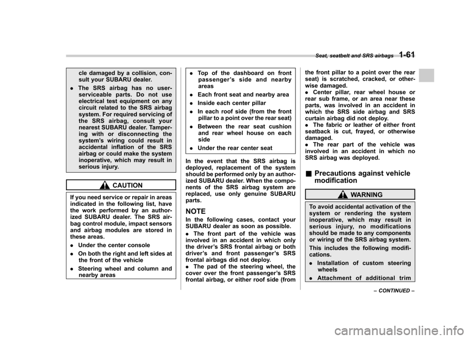
If you need service or repair in areas
indicated in the following list, have
the work performed by an author-
ized SUBARU dealer. The SRS air-
bag control module, impact sensors
and airbag modules are stored in
these areas. . Under the center console
. On both the right and left sides at
the front of the vehicle
. Steering wheel and column and
nearby areas .
Top of the dashboard on front
passenger ’s side and nearby
areas
. Each front seat and nearby area
. Inside each center pillar
. In each roof side (from the front
pillar to a point over the rear seat)
. Between the rear seat cushion
and rear wheel house on each side
. Under the rear center seat
In the event that the SRS airbag is
deployed, replacement of the system
should be performed only by an author-
ized SUBARU dealer. When the compo-
nents of the SRS airbag system are
replaced, use only genuine SUBARUparts. NOTE
In the following cases, contact your
SUBARU dealer as soon as possible. . The front part of the vehicle was
involved in an accident in which only
the driver ’s SRS frontal airbag or both
driver ’s and front passenger ’sSRS
frontal airbags did not deploy.. The pad of the steering wheel, the
cover over the front passenger ’s SRS
frontal airbag, or either roof side (from the front pillar to a point over the rear
seat) is scratched, cracked, or other-
wise damaged..
Center pillar, rear wheel house or
rear sub frame, or an area near these
parts, was involved in an accident in
which the SRS side airbag and SRS
curtain airbag did not deploy.. The fabric or leather of either front
seatback is cut, frayed, or otherwisedamaged.. The rear part of the vehicle was
involved in an accident in which no
SRS airbag was deployed. & Precautions against vehicle modification
WARNING
To avoid accidental activation of the
system or rendering the system
inoperative, which may result in
serious injury, no modifications
should be made to any components
or wiring of the SRS airbag system.
This includes the following modifi- cations. . Installation of custom steering
wheels
. Attachment of additional trim
Seat, seatbelt and SRS airbags
1-61
– CONTINUED –
Page 112 of 402

Ignition switch..................................................... 3-3
LOCK .................................................................. 3-3
Acc..................................................................... 3-4
ON...................................................................... 3-4
START ................................................................ 3-4
Key reminder chime ............................................ 3-5
Ignition switch light ............................................. 3-5
Hazard warning flasher ....................................... 3-5
Meters and gauges. ............................................. 3-5
Combination meter illumination ........................... 3-5
Canceling the function for meter/gauge needle movement upon turning on the ignition switch ............................................................... 3-6
Speedometer ....................................................... 3-6
Odometer/Trip meter ............................................ 3-6
Tachometer ......................................................... 3-8
Fuel gauge .......................................................... 3-8
Warning and indicator lights .............................. 3-9
Seatbelt warning light and chime ........................ 3-10
SRS airbag system warning light ........................ 3-11
Front passenger ’s frontal airbag ON and OFF
indicators ......................................................... 3-12
CHECK ENGINE warning light/Malfunction indicator lamp .................................................. 3-12
Coolant temperature low indicator light/Coolant temperature high warning light ......................... 3-13
Charge warning light .......................................... 3-14
Oil pressure warning light .................................. 3-14
AT OIL TEMP warning light (AT models) ... ........... 3-14
Low tire pressure warning light (U.S.-spec. models) .......................................... 3-15 ABS warning light
.............................................. 3-16
Brake system warning light ................................ 3-17
Low fuel warning light ....................................... 3-18
Hill start assist warning light (MT models) ..... ..... 3-18
Door open warning light .................................... 3-18
All-Wheel Drive warning light (AT models) ..... ..... 3-18
Automatic headlight beam leveler warning light (models with HID headlights).. .......................... 3-18
Vehicle Dynamics Control operation indicator light ................................................................ 3-19
Vehicle Dynamics Control warning light/Vehicle Dynamics Control OFF indicator light ............... 3-19
Security indicator light ....................................... 3-20
SPORT mode indicator light (AT models) ............ 3-20
Select lever and gear position indicator (AT models) ..................................................... 3-21
Turn signal indicator lights ................................. 3-21
High beam indicator light ................................... 3-21
Cruise control indicator light .............................. 3-21
Cruise control set indicator light ........................ 3-21
Front fog light indicator light (if equipped) ..... ..... 3-21
Headlight indicator light ..................................... 3-21
Clock .................................................................. 3-22
Information display ............................................ 3-22
Outside temperature indicator .. .......................... 3-23
Average fuel consumption ................................. 3-24
To turn off fuel consumption indicator display ............................................................ 3-24
Light control switch ........................................... 3-25
Headlights ......................................................... 3-25
High/low beam change (dimmer) ........................ 3-26
Instruments and controls
3
Page 113 of 402

Instruments and controlsHeadlight flasher ................................................ 3-26
Daytime running light system (if equipped) ... ...... 3-26
Automatic headlight beam leveler (models with HID headlights) ................................................ 3-27
Turn signal lever ................................................ 3-27
Illumination brightness control ......................... 3-27
Front fog light switch (if equipped) .................. 3-28
Wiper and washer .............................................. 3-29
Windshield wiper and washer switches ............... 3-30
Rear window wiper and washer switch ................ 3-31Mirrors
................................................................ 3-32
Inside mirror ...................................................... 3-32
Auto-dimming mirror/compass (if equipped) ....... 3-32
Auto-dimming mirror/compass with HomeLink
®(if equipped) .................................................... 3-34
Outside mirrors ................................................. 3-39
Defogger and deicer .......................................... 3-40
Tilt steering wheel (if equipped) ....................... 3-42
Tilt/telescopic steering wheel (if equipped) ..... 3-42
Horn .................................................................... 3-43
Page 114 of 402
Ignition switch
WARNING
. Never turn the ignition switch to
“ LOCK ”while the vehicle is
being driven or towed because
that will lock the steering wheel,
preventing steering control. And
when the engine is turned off, it
takes a much greater effort than
usual to steer.
. Before leaving the vehicle, al-
ways remove the key from the
ignition switch for safety and
never allow an unattended child
to remain in the vehicle. Failure
to follow this procedure could
result in injury to a child or
others. Children could operate
the power windows, the moon-
roof or other controls or even
make the vehicle move.
CAUTION
Do not attach a large key holder or
key case to either key. If it banged
against your knees or hands while
you are driving, it could turn the
ignition switch from the “ON ”posi- tion to the
“Acc ”or “LOCK ”posi-
tion, thereby stopping the engine.
Also, if the key is attached to a
keyholder or to a large bunch of
other keys, centrifugal force may act
on it as the vehicle moves, resulting
in unwanted turning of the ignitionswitch.
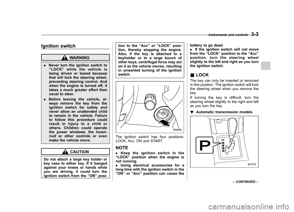
The ignition switch has four positions:
LOCK, Acc, ON and START. NOTE . Keep the ignition switch in the
“ LOCK ”position when the engine is
not running. . Using electrical accessories for a
long time with the ignition switch in the“ ON ”or “Acc ”position can cause the battery to go dead..
If the ignition switch will not move
from the “LOCK ”position to the “Acc ”
position, turn the steering wheel
slightly to the left and right as you turn
the ignition switch. & LOCK
The key can only be inserted or removed
in this position. The ignition switch will lock
the steering wheel when you remove the
key.
If turning the key is difficult, turn the
steering wheel slightly to the right and left
as you turn the key. ! Automatic transmission models
Instruments and controls 3-3
– CONTINUED –
Page 126 of 402
&Low tire pressure
warning light (U.S.-spec. models)
When the ignition switch is turned to the “ON ”position, the low tire pressure warn-
ing light will illuminate for approximately 2
seconds to check that the tire pressure
monitoring system (TPMS) is functioning
properly. If there is no problem and all tires
are properly inflated, the light will turn off.
Each tire, including the spare (if provided),
should be checked monthly when cold
and inflated to the inflation pressure
recommended by the vehicle manufac-
turer on the vehicle placard or tire inflation
pressure label. (If your vehicle has tires of
a different size than the size indicated on
the vehicle placard or tire inflation pres-
sure label, you should determine the
proper tire inflation pressure for thosetires.)
As an added safety feature, your vehicle
has been equipped with a tire pressure
monitoring system (TPMS) that illuminates
a low tire pressure telltale when one or
more of your tires is significantly under-
inflated. Accordingly, when the low tire
pressure telltale illuminates, you should
stop and check your tires as soon as
possible, and inflate them to the proper
pressure. Driving on a significantly under- inflated tire causes the tire to overheat and
can lead to tire failure. Under-inflation also
reduces fuel efficiency and tire tread life,
and may affect the vehicle
’s handling and
stopping ability.
Please note that the TPMS is not a
substitute for proper tire maintenance,
and it is the driver ’s responsibility to
maintain correct tire pressure, even if
under-inflation has not reached the level
to trigger illumination of the TPMS low tire
pressure telltale.
Your vehicle has also been equipped with
a TPMS malfunction indicator to indicate
when the system is not operating properly.
The TPMS malfunction indicator is com-
bined with the low tire pressure telltale.
When the system detects a malfunction,
the telltale will flash for approximately one
minute and then remain continuously
illuminated. This sequence will continue
upon subsequent vehicle start-ups as long
as the malfunction exists. When the
malfunction indicator is illuminated, the
system may not be able to detect or signal
low tire pressure as intended. TPMS
malfunctions may occur for a variety of
reasons, including the installation of re-
placement or alternate tires or wheels on
the vehicle that prevent the TPMS from
functioning properly. Always check the
TPMS malfunction telltale after replacing one or more tires or wheels on your
vehicle to ensure that the replacement or
alternate tires and wheels allow the TPMS
to continue to function properly.
Should the warning light illuminate stea-
dily after blinking for approximately one
minute, have the system inspected by
your nearest SUBARU dealer as soon aspossible.
WARNING
If this light does not illuminate
briefly after the ignition switch is
turned ON or the light illuminates
steadily after blinking for approxi-
mately one minute, you should have
your Tire Pressure Monitoring Sys-
tem checked at a SUBARU dealer as
soon as possible.
If this light illuminates while driving,
never brake suddenly and keep
driving straight ahead while gradu-
ally reducing speed. Then slowly
pull off the road to a safe place.
Otherwise an accident involving
serious vehicle damage and serious
personal injury could occur.
If this light still illuminates while
driving after adjusting the tire pres-
sure, a tire may have significant
damage and a fast leak that causes Instruments and controls
3-15
– CONTINUED –
Page 127 of 402
3-16Instruments and controls
the tire to lose air rapidly. If you have
a flat tire, replace it with a spare tire
as soon as possible.
When a spare tire is mounted or a
wheel rim is replaced without the
original pressure sensor/transmitter
being transferred, the Low tire pres-
sure warning light will illuminate
steadily after blinking for approxi-
mately one minute. This indicates
the TPMS is unable to monitor all
four road wheels. Contact your
SUBARU dealer as soon as possible
for tire and sensor replacement and/
or system resetting. If the light
illuminates steadily after blinking
for approximately one minute,
promptly contact a SUBARU dealer
to have the system inspected.
CAUTION
The tire pressure monitoring system
is NOT a substitute for manually
checking tire pressure. The tire
pressure should be checked peri-
odically (at least monthly) using a
tire gauge. After any change to tire
pressure(s), the tire pressure mon-
itoring system will not re-check tire
inflation pressures until the vehicle
is first driven more than 20 mph (32 km/h). After adjusting the tire pres-
sures, increase the vehicle speed to
at least 20 mph (32 km/h) to start the
TPMS re-checking of the tire infla-
tion pressures. If the tire pressures
are now above the severe low
pressure threshold, the low tire
pressure warning light should turn
off a few minutes later. Therefore, be
sure to install the specified size for
the front and rear tires.
& ABS warning light
The ABS warning light illuminates when
the ignition switch is turned to the “ON ”
position and turns off after approximately 2seconds.
This is an indication that the ABS system
is working properly.
CAUTION
If the warning light behaves as
follows, the ABS system may not
work properly.
When the warning light is on, the
ABS function shuts down; however,
the conventional brake system con-
tinues to operate normally. . The warning light does not illu-
minate when the ignition switch is turned to the
“ON ”position.
. The warning light illuminates
when the ignition switch is
turned to the “ON ”position, but
it does not turn off even when the
vehicle speed exceeds approxi-
mately 8 mph (12 km/h).
. The warning light illuminates dur-
ing driving.
If any of these conditions occur,
have the ABS system repaired at
the first available opportunity by
your SUBARU dealer.
With a vehicle equipped with an EBD
system, the ABS warning light illuminates
together with the brake system warning
light if the EBD system becomes faulty.
For further details of the EBD system fault
warning, refer to “Brake system warning
light ”F 3-17.
NOTE
If the warning light behavior is as
described in the following, the ABS
system may be considered normal. . The warning light illuminates right
after the engine is started but turns off
immediately, remaining off.. The warning light remains on after
the engine has been started, but it
turns off when the vehicle speed