ESP SUBARU FORESTER 2010 SH / 3.G Owner's Manual
[x] Cancel search | Manufacturer: SUBARU, Model Year: 2010, Model line: FORESTER, Model: SUBARU FORESTER 2010 SH / 3.GPages: 402, PDF Size: 14.36 MB
Page 150 of 402
begins to flash slowly (after approximately
20 seconds), position the hand-held trans-
mitter of the device between 1 to 3 inches
(25 to 76 mm) away from the HomeLink
®button you wish to program.
3. Press and hold the hand-held trans-
mitter button. The HomeLink
®indicator
light will flash, first slowly and then rapidly.
4. When the indicator light begins to flash
rapidly, release both buttons.
The programming for the previous device
is now erased and the new device can be
operated by pressing the HomeLink
®button. ! Erasing HomeLink
®button memory
NOTE . Performing this procedure erases
the memory of all the preprogrammed
buttons simultaneously. The memory
of individual buttons cannot be erased.. It is recommended that upon the
sale of the vehicle, the memory of all
programmed HomeLink
®buttons be
erased for security purposes.
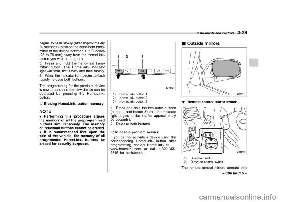
1) HomeLink®button 1
2) HomeLink®button 2
3) HomeLink®button 3
1. Press and hold the two outer buttons
(button 1 and button 3) until the indicator
light begins to flash (after approximately
20 seconds).
2. Release both buttons. ! In case a problem occurs
If you cannot activate a device using the
corresponding HomeLink
®button after
programming, contact HomeLink®at
www.homelink.com or call 1-800-355-
3515 for assistance. &
Outside mirrors
! Remote control mirror switch
1) Selection switch
2) Direction control switch
The remote control mirrors operate only Instruments and controls
3-39
– CONTINUED –
Page 160 of 402
WARNING
Continued operation with the air
inletselectionbuttonintheON
position may fog up the windows.
Switch to the OFF position as soon
as the outside dusty conditionclears.
& Heater operation
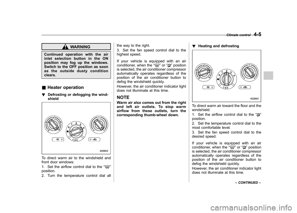
! Defrosting or defogging the wind-shield
To direct warm air to the windshield and
front door windows:
1. Set the airflow control dial to the “
”
position.
2. Turn the temperature control dial all the way to the right.
3. Set the fan speed control dial to the
highest speed.
If your vehicle is equipped with an air
conditioner, when the
“
”or “”position
is selected, the air conditioner compressor
automatically operates regardless of the
position of the air conditioner button to
defog the windshield quickly.
However, the air conditioner indicator light
does not illuminate at this time. NOTE
Warm air also comes out from the right
and left air outlets. To stop warm
airflow from these outlets, turn the
corresponding thumb-wheel down. !
Heating and defrosting
To direct warm air toward the floor and the windshield:
1. Set the airflow control dial to the “
”
position.
2. Set the temperature control dial to the
most comfortable level.
3. Set the fan speed control dial to the
desired speed.
If your vehicle is equipped with an air
conditioner, when the “
”or “”position
is selected, the air conditioner compressor
automatically operates regardless of the
position of the air conditioner button to
defog the windshield quickly.
However, the air conditioner indicator light
does not illuminate at this time. Climate control
4-5
– CONTINUED –
Page 161 of 402
4-6Climate control
NOTE
Warm air also comes out from the right
andleftairoutlets.Tostopwarm
airflow from these outlets, turn the
corresponding thumb-wheel down. ! Heating
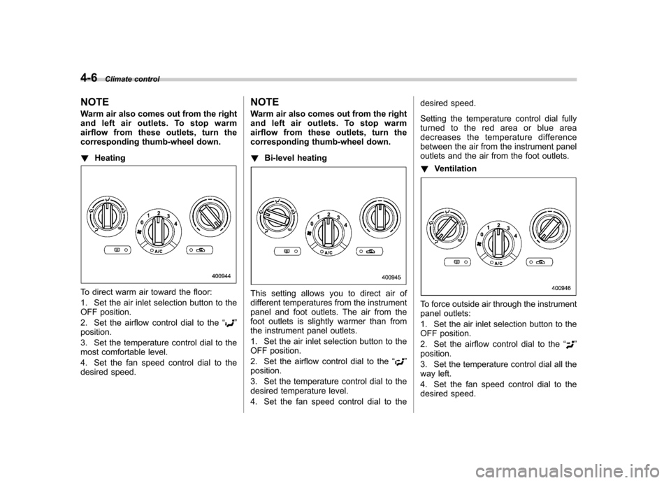
To direct warm air toward the floor:
1. Set the air inlet selection button to the
OFF position.
2. Set the airflow control dial to the “
”
position.
3. Set the temperature control dial to the
most comfortable level.
4. Set the fan speed control dial to the
desired speed. NOTE
Warm air also comes out from the right
and left air outlets. To stop warm
airflow from these outlets, turn the
corresponding thumb-wheel down. !
Bi-level heating
This setting allows you to direct air of
different temperatures from the instrument
panel and foot outlets. The air from the
foot outlets is slightly warmer than from
the instrument panel outlets.
1. Set the air inlet selection button to the
OFF position.
2. Set the airflow control dial to the “
”
position.
3. Set the temperature control dial to the
desired temperature level.
4. Set the fan speed control dial to the desired speed.
Setting the temperature control dial fully
turned to the red area or blue area
decreases the temperature difference
between the air from the instrument panel
outlets and the air from the foot outlets. !
Ventilation
To force outside air through the instrument
panel outlets:
1. Set the air inlet selection button to the
OFF position.
2. Set the airflow control dial to the “
”
position.
3. Set the temperature control dial all the
way left.
4. Set the fan speed control dial to the
desired speed.
Page 188 of 402
CD player operation NOTE .Make sure to always insert a disc
with the label side up. If a disc is
inserted with the label side down, the
player displays “CHECK DISC ”. Refer
to “When the following messages are
displayed ”F 5-25.
. If a disc is inserted during a radio
broadcast, the disc will interrupt thebroadcast.. After the last song finishes, the disc
will automatically return to track 1 (the
first track on the disc) and will auto-
matically play back. . The player is designed to be able to
play music CD-Rs and music CD-RWs,
but it may not be able to play certainones.. CDs (i.e., 8 cm/3 inch CDs) are not
supported, and if inserted, they will be
immediately ejected.. A file (track) that is protected by a
WMA copyright cannot be played, and
the player will skip to the next file(track). &
How to insert a CD (type A)
Hold a disc with a finger in the center hole
while gripping the edge of the disc, then
insert it in to the slot (with the label side
up) and the player will automatically pull
the disc into position. NOTE
DO NOT INSERT TWO DISCS INTO THE
DISC INSERTION SLOT AT THE SAMETIME. & How to insert a CD(s) (type B)
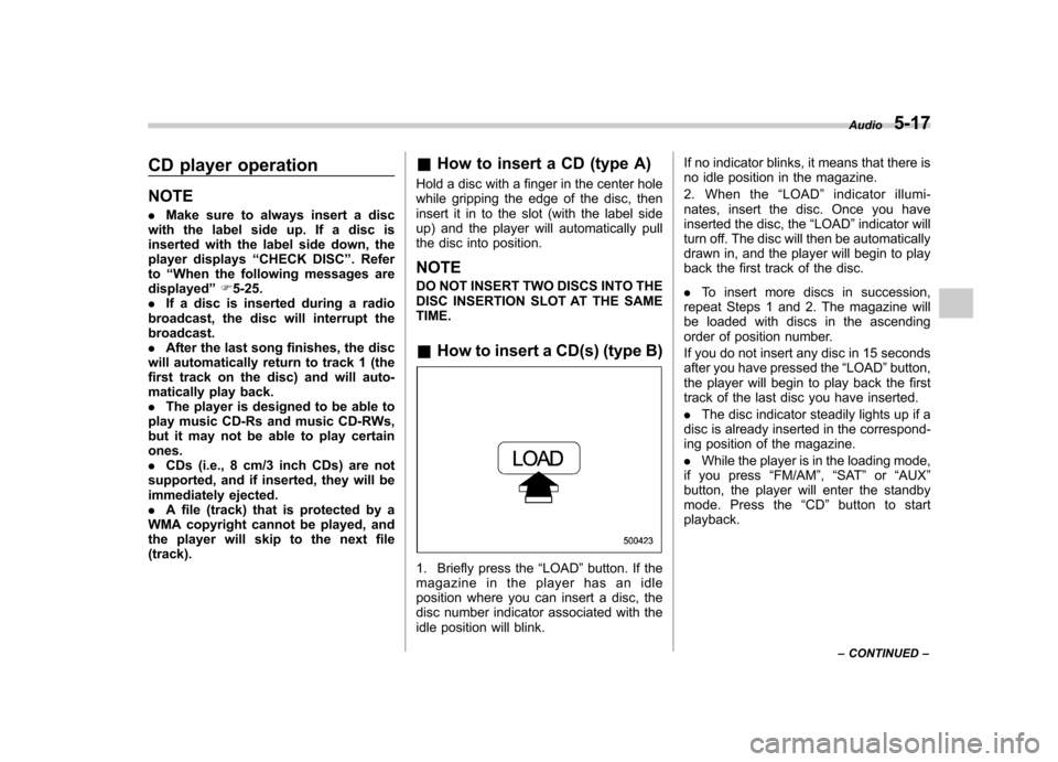
1. Briefly press the “LOAD ”button. If the
magazine in the player has an idle
position where you can insert a disc, the
disc number indicator associated with the
idle position will blink. If no indicator blinks, it means that there is
no idle position in the magazine.
2. When the
“LOAD ”indicator illumi-
nates, insert the disc. Once you have
inserted the disc, the “LOAD ”indicator will
turn off. The disc will then be automatically
drawn in, and the player will begin to play
back the first track of the disc. . To insert more discs in succession,
repeat Steps 1 and 2. The magazine will
be loaded with discs in the ascending
order of position number.
If you do not insert any disc in 15 seconds
after you have pressed the “LOAD ”button,
the player will begin to play back the first
track of the last disc you have inserted. . The disc indicator steadily lights up if a
disc is already inserted in the correspond-
ing position of the magazine. . While the player is in the loading mode,
if you press “FM/AM ”, “SAT ”or “AUX ”
button, the player will enter the standby
mode. Press the “CD ”button to start
playback. Audio
5-17
– CONTINUED –
Page 211 of 402
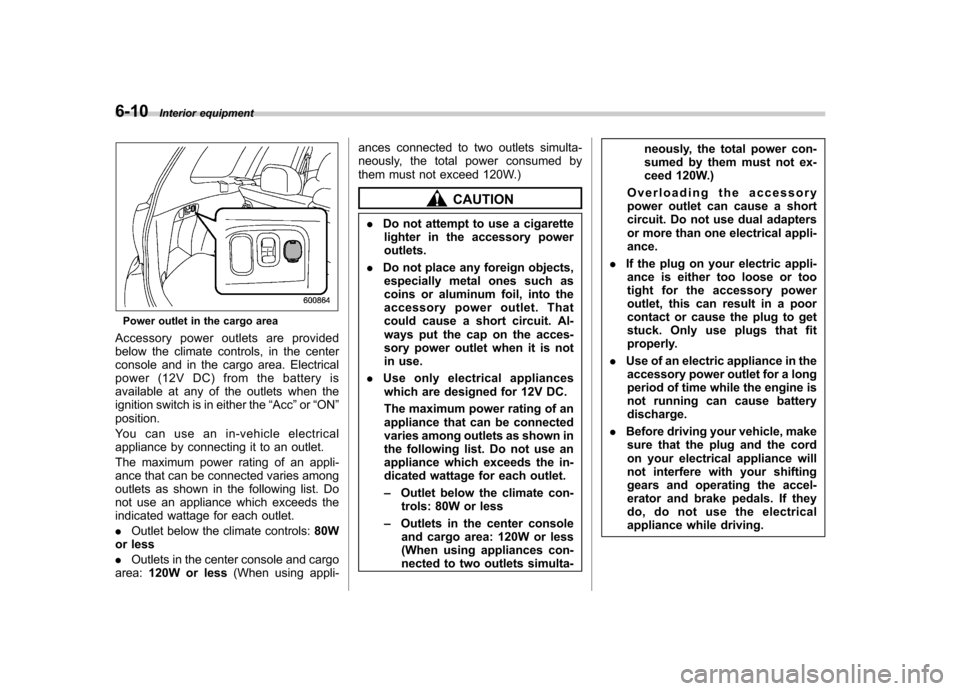
6-10Interior equipment
Power outlet in the cargo area
Accessory power outlets are provided
below the climate controls, in the center
console and in the cargo area. Electrical
power (12V DC) from the battery is
available at any of the outlets when the
ignition switch is in either the “Acc ”or “ON ”
position.
Youcanuseanin-vehicleelectrical
appliance by connecting it to an outlet.
The maximum power rating of an appli-
ance that can be connected varies among
outlets as shown in the following list. Do
not use an appliance which exceeds the
indicated wattage for each outlet. . Outlet below the climate controls: 80W
or less. Outlets in the center console and cargo
area: 120W or less (When using appli- ances connected to two outlets simulta-
neously, the total power consumed by
them must not exceed 120W.)
CAUTION
. Do not attempt to use a cigarette
lighter in the accessory power outlets.
. Do not place any foreign objects,
especially metal ones such as
coins or aluminum foil, into the
accessory power outlet. That
could cause a short circuit. Al-
ways put the cap on the acces-
sory power outlet when it is not
in use.
. Use only electrical appliances
which are designed for 12V DC.
The maximum power rating of an
appliance that can be connected
varies among outlets as shown in
the following list. Do not use an
appliance which exceeds the in-
dicated wattage for each outlet. – Outlet below the climate con-
trols: 80W or less
– Outlets in the center console
and cargo area: 120W or less
(When using appliances con-
nected to two outlets simulta- neously, the total power con-
sumed by them must not ex-
ceed 120W.)
Overloading the accessory
power outlet can cause a short
circuit. Do not use dual adapters
or more than one electrical appli-ance.
. If the plug on your electric appli-
ance is either too loose or too
tight for the accessory power
outlet, this can result in a poor
contact or cause the plug to get
stuck. Only use plugs that fit
properly.
. Use of an electric appliance in the
accessory power outlet for a long
period of time while the engine is
not running can cause batterydischarge.
. Before driving your vehicle, make
sure that the plug and the cord
on your electrical appliance will
not interfere with your shifting
gears and operating the accel-
erator and brake pedals. If they
do, do not use the electrical
appliance while driving.
Page 219 of 402
7-2Starting and operating
Fuel
CAUTION
Use of a fuel which is low in quality
or use of an inappropriate fuel
additive may cause engine damage.
& Fuel requirements
! Non-turbo models
The 2.5-liter non-turbo engine is designed
to operate using unleaded gasoline with
an octane rating of 87 AKI or higher.
! Turbo models
The 2.5-liter turbo engine is designed to
operate using premium unleaded gaso-
line with an octane rating of 91 AKI or
higher . If premium unleaded gasoline is
not available, regular unleaded gasoline
with an octane rating of 87 AKI or higher
may be temporarily used. For optimum
engine performance and driveability, it is
required that you use premium grade
unleaded gasoline. NOTE
Be sure to use premium unleaded
gasoline of 91 AKI or higher for turbo
engine models. If other gasoline (lower than 91 AKI) is used, knocking, re-
duced output and poor accelerator
response will result. !
Fuel octane rating
This octane rating is the average of the
Research Octane and Motor Octane
numbers and is commonly referred to as
the Anti Knock Index (AKI).
Using a gasoline with a lower octane
rating can cause persistent and heavy
knocking, which can damage the engine.
Do not be concerned if your vehicle
sometimes knocks lightly when you drive
up a hill or when you accelerate. Contact
your SUBARU dealer if you use a fuel with
the specified octane rating and your
vehicle knocks heavily or persistently. ! Unleaded gasoline
The neck of the fuel filler pipe is designed
to accept only an unleaded gasoline filler
nozzle. Under no circumstances should
leaded gasoline be used because it will
damage the emission control system and
may impair driveability and fuel economy. ! Gasoline for California-certified LEV
If your vehicle was certified to California ’s
low emission vehicle (LEV) standards as
indicated on the underhood tune-up label,
it is designed to optimize engine and emission performance with gasoline that
meets the clean burning low-sulfur Cali-
fornia gasoline specifications. If you live in
any other state than California, your
vehicle will operate on gasoline meeting
Federal specifications. Gasoline sold out-
side California is permitted to have higher
sulfur levels, which may affect the perfor-
mance of your vehicle
’s catalytic converter
and may produce a sulfur exhaust odor or
smell. SUBARU recommends that you try
a different brand of unleaded gasoline
having lower sulfur to determine if the
problem is fuel related before returning
your vehicle to an authorized dealer forservice. ! MMT
Some gasoline contains an octane-en-
hancing additive called MMT (Methylcy-
clopentadienyl Manganese Tricarbonyl). If
you use such fuels, your emission control
system performance may deteriorate and
the CHECK ENGINE warning light/Mal-
function indicator lamp may turn on. If this
happens, return to your authorized
SUBARU Dealer for service. If it is
determined that the condition is caused
by the type of fuel used, repairs may not
be covered by your warranty.
Page 221 of 402
7-4Starting and operating
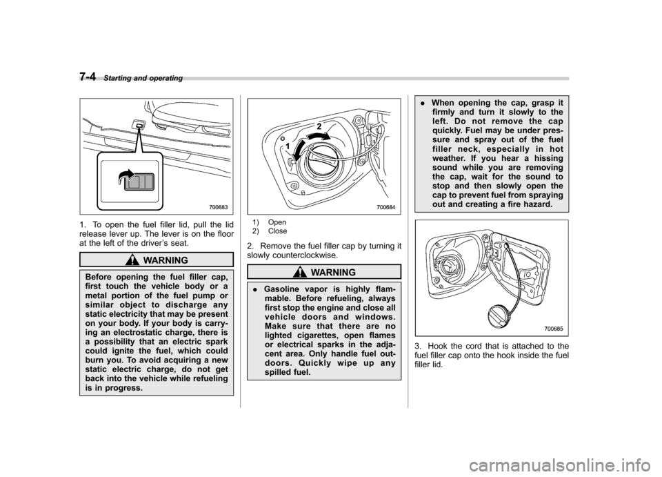
1. To open the fuel filler lid, pull the lid
release lever up. The lever is on the floor
at the left of the driver ’s seat.
WARNING
Before opening the fuel filler cap,
first touch the vehicle body or a
metal portion of the fuel pump or
similar object to discharge any
static electricity that may be present
on your body. If your body is carry-
ing an electrostatic charge, there is
a possibility that an electric spark
could ignite the fuel, which could
burn you. To avoid acquiring a new
static electric charge, do not get
back into the vehicle while refueling
is in progress.
1) Open
2) Close
2. Remove the fuel filler cap by turning it
slowly counterclockwise.
WARNING
. Gasoline vapor is highly flam-
mable. Before refueling, always
first stop the engine and close all
vehicle doors and windows.
Make sure that there are no
lighted cigarettes, open flames
or electrical sparks in the adja-
cent area. Only handle fuel out-
doors. Quickly wipe up any
spilled fuel. .
When opening the cap, grasp it
firmly and turn it slowly to the
left. Do not remove the cap
quickly. Fuel may be under pres-
sure and spray out of the fuel
filler neck, especially in hot
weather. If you hear a hissing
sound while you are removing
the cap, wait for the sound to
stop and then slowly open the
cap to prevent fuel from spraying
out and creating a fire hazard.
3. Hook the cord that is attached to the
fuel filler cap onto the hook inside the fuel
filler lid.
Page 223 of 402
7-6Starting and operating
State emission testing (U.S. only)
At state inspection time, remember to
tell your inspection or service station in
advance not to place your SUBARU
AWD vehicle on a two-wheel dynam-
ometer. Otherwise, serious transmis-
sion damage will result.
Some states have started using dynam-
ometers in their state inspection programs
in order to meet their obligation under
federal law to implement stricter vehicle
emission standards to reduce air pollution
from vehicles. A dynamometer is a tread-
mill or roller-like testing device that allows
your vehicle ’s wheels to turn while the
vehicle remains in one place. Depending
on the severity of a state ’s air pollution
problems, the states must adopt either a“ basic ”or “enhanced ”vehicle emission
inspection test. Normally, a portion of the
basic emission test consists of an emis-
sion inspector inserting an analyzer probe
into the exhaust pipe of an idling vehicle
for a short period of time. States with more
severe air pollution problems are required
to adopt an enhanced vehicle emission
test. This test simulates actual driving
conditions on a dynamometer and permits
more accurate measurement of tailpipe
emitted pollution than the basic emission test.
The U.S. Environmental Protection
Agency (EPA) and states using two-wheel
dynamometers in their emission testing
programs have
EXEMPTEDSUBARU
AWD vehicles from the portion of the
testing program that involves a two-wheel
dynamometer.
There are some states that use four-wheel
dynamometers in their testing programs.
When properly used, that equipment will
not damage a SUBARU AWD vehicle.
Under no circumstances should the rear
wheels be jacked off the ground, nor
should the driveshaft be disconnected for
state emission testing.
WARNING
Testing of an All-Wheel Drive vehicle
must NEVER be performed on a
single two-wheel dynamometer. At-
tempting to do so will result in
uncontrolled vehicle movement and
may cause an accident or injuries to
persons nearby.
CAUTION
Resultant vehicle damage due to
improper testing is not covered
under the SUBARU Limited War-
ranty and is the responsibility of
the state inspection program or its
contractors or licensees.
The EPA has issued regulations for
inspecting the On-Board Diagnostic
(OBD) system as part of the state emis-
sions inspection. The OBD system is
designed to detect engine and transmis-
sion problems that might cause vehicle
emissions to exceed allowable limits.
These inspections apply to all 1996 model
year and newer passenger cars and light
trucks. Over 30 states plus the District of
Columbia have implemented the OBD
system inspection. . The inspection of the OBD system
consists of a visual operational check of the “CHECK ENGINE ”warning light/mal-
function indicator lamp (MIL) and an
examination of the OBD system with an
electronic scan tool while the engine isrunning. . Avehicle
passes the OBD system
inspection if proper illumination of the “ CHECK ENGINE ”warning light/MIL is
observed, there are nostored diagnostic
Page 230 of 402
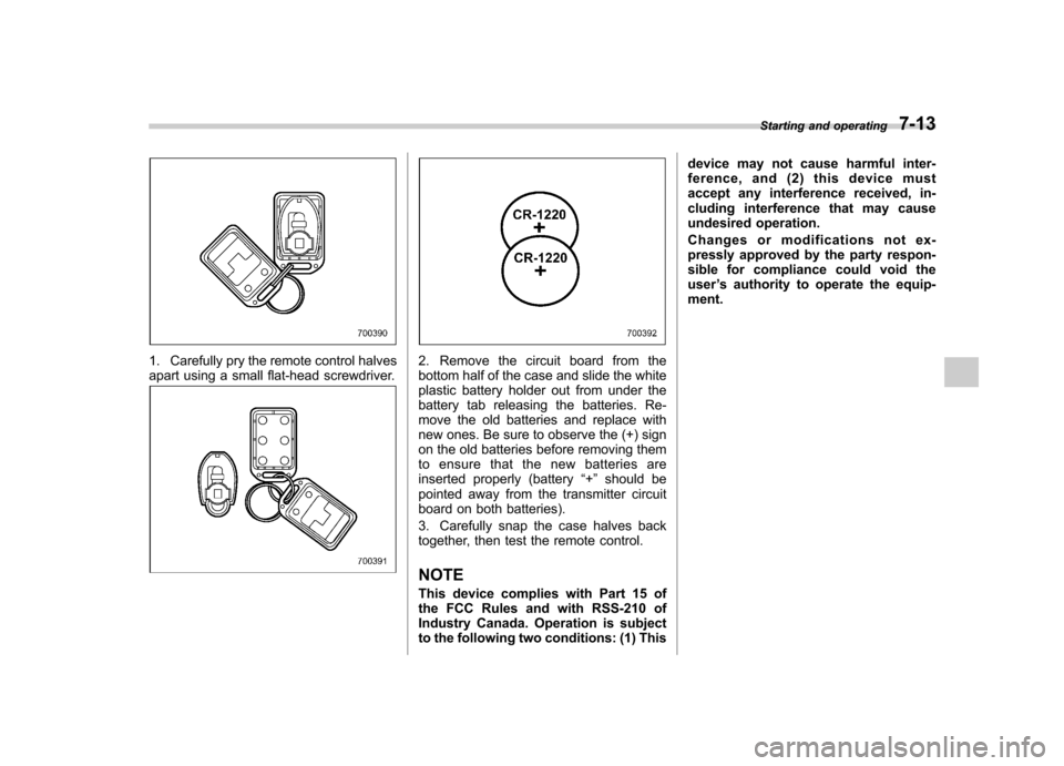
1. Carefully pry the remote control halves
apart using a small flat-head screwdriver.2. Remove the circuit board from the
bottom half of the case and slide the white
plastic battery holder out from under the
battery tab releasing the batteries. Re-
move the old batteries and replace with
new ones. Be sure to observe the (+) sign
on the old batteries before removing them
to ensure that the new batteries are
inserted properly (battery“+ ” should be
pointed away from the transmitter circuit
board on both batteries).
3. Carefully snap the case halves back
together, then test the remote control.
NOTE
This device complies with Part 15 of
the FCC Rules and with RSS-210 of
Industry Canada. Operation is subject
to the following two conditions: (1) This device may not cause harmful inter-
ference, and (2) this device must
accept any interference received, in-
cluding interference that may cause
undesired operation.
Changes or modifications not ex-
pressly approved by the party respon-
sible for compliance could void theuser
’s authority to operate the equip-
ment. Starting and operating
7-13
Page 237 of 402
7-20Starting and operating
. If you attempt to shift up when the
vehicle speed is too low, the transmis-
sion will not respond.. You can perform a skip-shift (for
example, from 4th to 2nd) by operating
the select lever twice in rapid succes-sion.. The transmission automatically se-
lects 1st gear when the vehicle stopsmoving.. If the temperature of the automatic
transmission fluid becomes too high,the “AT OIL TEMP ”warning light will
illuminate and upshifts to 4th gear will
not be possible. Immediately stop the
vehicle in a safe place and let the
engine idle until the warning light turns off.
& Driving tips
. On a road surface where there is a risk
of wheelspin (for example, a snow- or
gravel-covered road), you can pull away
from a standstill (safely and easily) by first
selecting the 2nd gear of the manual mode. . Always apply the foot or parking brake
when the vehicle is stopped in the “D ”or
“ R ”position.
. Always set the parking brake when
parking your vehicle. Do not hold the
vehicle with only the transmission. .
Do not keep the vehicle in a stationary
position on an uphill grade by using the“ D ”position. Use the brake instead.
. The engine may, on rare occasions,
knock when the vehicle rapidly acceler-
ates or rapidly pulls away from a standstill.
This phenomenon does not indicate aproblem.
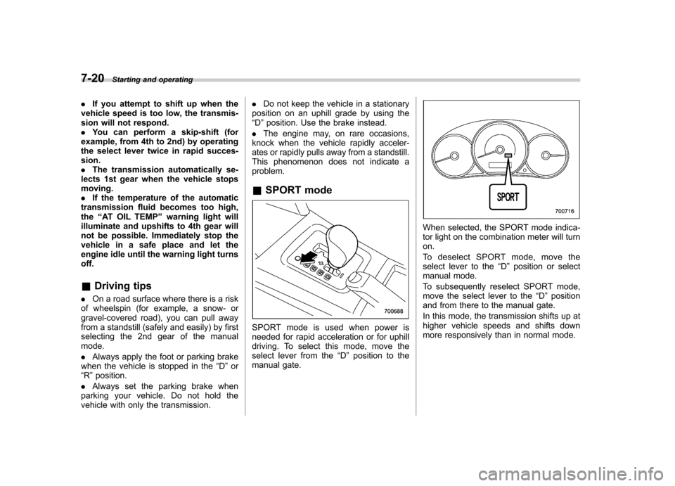
& SPORT mode
SPORT mode is used when power is
needed for rapid acceleration or for uphill
driving. To select this mode, move the
select lever from the “D ” position to the
manual gate.
When selected, the SPORT mode indica-
tor light on the combination meter will turnon.
To deselect SPORT mode, move the
select lever to the “D ” position or select
manual mode.
To subsequently reselect SPORT mode,
move the select lever to the “D ” position
and from there to the manual gate.
In this mode, the transmission shifts up at
higher vehicle speeds and shifts down
more responsively than in normal mode.