warning SUBARU FORESTER 2010 SH / 3.G Manual PDF
[x] Cancel search | Manufacturer: SUBARU, Model Year: 2010, Model line: FORESTER, Model: SUBARU FORESTER 2010 SH / 3.GPages: 402, PDF Size: 14.36 MB
Page 135 of 402

3-24Instruments and controls
“ ON ”position, the indication does not
flash. NOTE
The outside temperature indication
may differ from the actual outside
temperature. The road surface freeze
warning indication should be treated
only as a guide. Be sure to check the
condition of the road surface beforedriving. & Average fuel consumption
1) U.S.-spec. models
2) Except U.S.-spec. models
This indication shows the average rate of
fuel consumption since the trip meter was
last reset. When either of the trip meter indications is
reset, the corresponding average fuel
consumption value is also reset.
NOTE . The indicated values vary in accor-
dance with changes in the vehicle ’s
running conditions. Also, the indicated
values may differ slightly from the
actual values and should thus be
treated only as a guide.. When either trip meter indication is
reset, the average fuel consumption
corresponding to that trip meter indica-
tion is not shown until the vehicle has
subsequently covered a distance of 1
mile (or 1 km). & To turn off fuel consumption
indicator display
The fuel consumption indicator display
can be turned off.
To turn off this display, turn the ignition
switch to the “LOCK ”position and press
the “+ ” button adjacent to the information
display for approximately 5 seconds.
Then, the information display and the
clock display will blink for 3 seconds to
notify you that the fuel consumption dis-
play has been turned off.
To restore the indicator, once again pressthe “+ ” button for approximately 5 sec- onds.
NOTE . The initial display setting of the fuel
consumption indicator of your vehicle
has been set to operational at the time
of shipment from the factory. . The average fuel consumption is
calculated even while the indicator is
not displayed.. Even if you turn off the fuel con-
sumption indicator, the fuel consump-
tion indicator will automatically turn on
when the battery voltage is discon-
nected and then reconnected for bat-
tery replacement or fuse replacement.
Page 137 of 402
3-26Instruments and controls
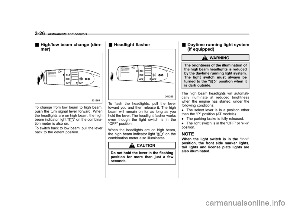
&High/low beam change (dim- mer)
To change from low beam to high beam,
push the turn signal lever forward. When
the headlights are on high beam, the high
beam indicator light “
”on the combina-
tion meter is also on.
To switch back to low beam, pull the lever
back to the detent position. &
Headlight flasher
To flash the headlights, pull the lever
toward you and then release it. The high
beam will remain on for as long as you
hold the lever. The headlight flasher works
even though the light switch is in the“OFF ”position.
When the headlights are on high beam,
the high beam indicator light “
”on the
combination meter also illuminates.
CAUTION
Do not hold the lever in the flashing
position for more than just a fewseconds. &
Daytime running light system
(if equipped)
WARNING
The brightness of the illumination of
the high beam headlights is reduced
by the daytime running light system.
The light switch must always be
turned to the “
”position when it
is dark outside.
The high beam headlights will automati-
cally illuminate at reduced brightness
when the engine has started, under the
following conditions: . The select lever is in a position other
than the “P ”position (AT models).
. The parking brake is fully released.
. The light switch is in the “OFF ”or “
”
position.
NOTE
When the light switch is in the “
”
position, the front side marker lights,
tail lights and license plate lights are
also illuminated.
Page 140 of 402
Wiper and washer
WARNING
In freezing weather, do not use the
windshield washer until the wind-
shield is sufficiently warmed by the
defroster.
Otherwise the washer fluid can
freeze on the windshield, blocking
your view.
CAUTION
. Do not operate the washer con-
tinuously for more than 10 sec-
onds, or when the washer fluid
tank is empty. This may cause
overheating of the washer motor.
Check the washer fluid level
frequently, such as at fuel stops.
. Do not operate the wipers when
the windshield or rear window is
dry. This may scratch the glass,
damage the wiper blades and
cause the wiper motor to burn
out. Before operating the wiper
on a dry windshield or rear
window, always use the wind-
shield washer. .
In freezing weather, be sure that
the wiper blades are not frozen to
the windshield or rear window
before switching on the wipers.
Attempting to operate the wiper
with the blades frozen to the
window glass could cause not
only the wiper blades to be
damaged but also the wiper mo-
tor to burn out. If the wiper
blades are frozen to the window
glass, be sure to operate the
defroster, windshield wiper dei-
cer (if equipped) or rear window
defogger before turning on the
wiper.
. If the wipers stop during opera-
tion because of ice or some other
obstruction on the window, the
wiper motor could burn out even
if the wiper switch is turned off. If
this occurs, promptly stop the
vehicle in a safe place, turn the
ignition switch to the “LOCK ”
position and clean the window
glass to allow proper wiper op-eration.
. Use clean water if windshield
washer fluid is unavailable. In
areas where water freezes in
winter, use SUBARU Windshield
Washer Fluid or the equivalent. Refer to
“Windshield washer
fluid ”F 11-38.
Also, when driving the vehicle
when there are freezing tempera-
tures, use non-freezing type wi-
per blades.
. Do not clean the wiper blades
with gasoline or a solvent, such
as paint thinner or benzine. This
will cause deterioration of the
wiper blades.
NOTE . The wiper operates only when the
ignition switch is in the “ON ”or “Acc ”
position. . The front wiper motor is protected
against overloads by a circuit breaker.
If the motor operates continuously
under an unusually heavy load, the
circuit breaker may trip to stop the
motor temporarily. If this happens, park
your vehicle in a safe place, turn off the
wiper switch, and wait for approxi-
mately 10 minutes. The circuit breaker
will reset itself, and the wipers will
again operate normally.. Clean your wiper blades and win-
dow glass periodically with a washer
solution to prevent streaking, and to
remove accumulations of road salt or Instruments and controls
3-29
– CONTINUED –
Page 146 of 402
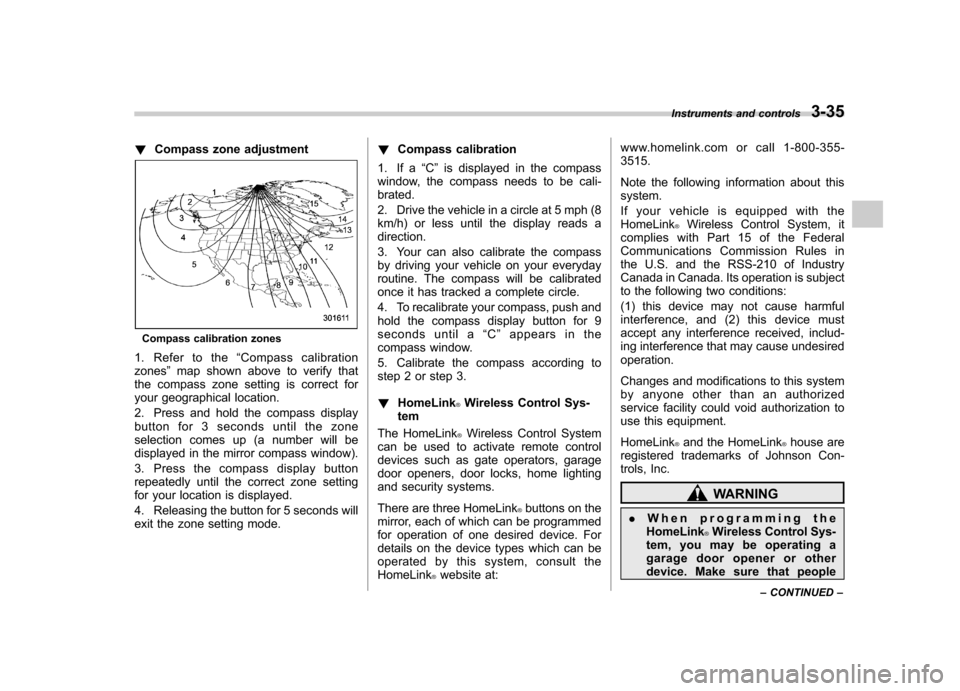
!Compass zone adjustment
Compass calibration zones
1. Refer to the “Compass calibration
zones ”map shown above to verify that
the compass zone setting is correct for
your geographical location.
2. Press and hold the compass display
button for 3 seconds until the zone
selection comes up (a number will be
displayed in the mirror compass window).
3. Press the compass display button
repeatedly until the correct zone setting
for your location is displayed.
4. Releasing the button for 5 seconds will
exit the zone setting mode. !
Compass calibration
1. If a “C ” is displayed in the compass
window, the compass needs to be cali-brated.
2. Drive the vehicle in a circle at 5 mph (8
km/h) or less until the display reads a direction.
3. Your can also calibrate the compass
by driving your vehicle on your everyday
routine. The compass will be calibrated
once it has tracked a complete circle.
4. To recalibrate your compass, push and
hold the compass display button for 9
seconds until a “C ” appears in the
compass window.
5. Calibrate the compass according to
step 2 or step 3. ! HomeLink
®Wireless Control Sys-
tem
The HomeLink
®Wireless Control System
can be used to activate remote control
devices such as gate operators, garage
door openers, door locks, home lighting
and security systems.
There are three HomeLink
®buttons on the
mirror, each of which can be programmed
for operation of one desired device. For
details on the device types which can be
operated by this system, consult the HomeLink
®website at: www.homelink.com or call 1-800-355-3515.
Note the following information about this system.
If your vehicle is equipped with the HomeLink
®Wireless Control System, it
complies with Part 15 of the Federal
Communications Commission Rules in
the U.S. and the RSS-210 of Industry
Canada in Canada. Its operation is subject
to the following two conditions:
(1) this device may not cause harmful
interference, and (2) this device must
accept any interference received, includ-
ing interference that may cause undesiredoperation.
Changes and modifications to this system
by anyone other than an authorized
service facility could void authorization to
use this equipment. HomeLink
®and the HomeLink®house are
registered trademarks of Johnson Con-
trols, Inc.
WARNING
. When programming the
HomeLink
®Wireless Control Sys-
tem, you may be operating a
garage door opener or other
device. Make sure that people Instruments and controls
3-35
– CONTINUED –
Page 153 of 402
3-42Instruments and controls
necessary.
. Do not use sharp instruments or
window cleaner containing abra-
sives to clean the inner surface
of the rear window. They may
damage the conductors printed
on the window.
NOTE . Turn on the defogger and deicer
system if the wipers are frozen to the windshield.. If the windshield is covered with
snow, remove the snow so that the
windshield wiper deicer works effec-
tively.. While the defogger and deicer sys-
tem is in the continuous operation
mode, if the vehicle speed remains at
9 mph (15 km/h) or less for 15 minutes,
the windshield wiper deicer automati-
cally stops operating, though the rear
window defogger and outside mirror
defogger maintain continuous opera-
tion in this condition.. While the defogger and deicer sys-
tem is in the continuous operation
mode, if the battery voltage drops
below the permissible level, continu-
ous operation of the defogger and
deicer system is canceled and the system stops operating.
Tilt/telescopic steering wheel
WARNING
. Do not adjust the steering wheel
tilt/telescopic position while driv-
ing. This may cause loss of
vehicle control and result in
personal injury.
. If the lever cannot be raised to
the fixed position, adjust the
steering wheel again. It is dan-
gerous to drive without locking
the steering wheel. This may
cause loss of vehicle control
and result in personal injury.
Page 160 of 402
WARNING
Continued operation with the air
inletselectionbuttonintheON
position may fog up the windows.
Switch to the OFF position as soon
as the outside dusty conditionclears.
& Heater operation
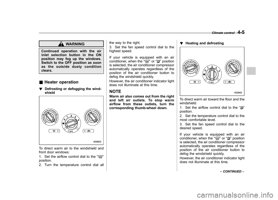
! Defrosting or defogging the wind-shield
To direct warm air to the windshield and
front door windows:
1. Set the airflow control dial to the “
”
position.
2. Turn the temperature control dial all the way to the right.
3. Set the fan speed control dial to the
highest speed.
If your vehicle is equipped with an air
conditioner, when the
“
”or “”position
is selected, the air conditioner compressor
automatically operates regardless of the
position of the air conditioner button to
defog the windshield quickly.
However, the air conditioner indicator light
does not illuminate at this time. NOTE
Warm air also comes out from the right
and left air outlets. To stop warm
airflow from these outlets, turn the
corresponding thumb-wheel down. !
Heating and defrosting
To direct warm air toward the floor and the windshield:
1. Set the airflow control dial to the “
”
position.
2. Set the temperature control dial to the
most comfortable level.
3. Set the fan speed control dial to the
desired speed.
If your vehicle is equipped with an air
conditioner, when the “
”or “”position
is selected, the air conditioner compressor
automatically operates regardless of the
position of the air conditioner button to
defog the windshield quickly.
However, the air conditioner indicator light
does not illuminate at this time. Climate control
4-5
– CONTINUED –
Page 162 of 402
When driving on a dusty road, set the air
inlet selection button to the“ON ”position.
WARNING
Continued operation with the air
inletselectionbuttonintheON
position may fog up the windows.
Switch to the OFF position as soon
as the outside dusty conditionclears.
& Air conditioner operation
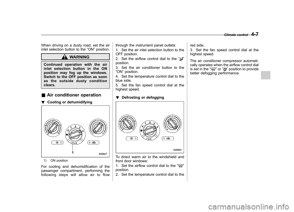
! Cooling or dehumidifying
1) ON position
For cooling and dehumidification of the
passenger compartment, performing the
following steps will allow air to flow through the instrument panel outlets:
1. Set the air inlet selection button to the
OFF position.
2. Set the airflow control dial to the
“
”
position.
3. Set the air conditioner button to the “ ON ”position.
4. Set the temperature control dial to the
blue side.
5. Set the fan speed control dial at the
highest speed. ! Defrosting or defogging
To direct warm air to the windshield and
front door windows:
1. Set the airflow control dial to the “
”
position.
2. Set the temperature control dial to the red side.
3. Set the fan speed control dial at the
highest speed.
The air conditioner compressor automati-
cally operates when the airflow control dial
is set in the
“
”or “”position to provide
better defogging performance. Climate control
4-7
Page 165 of 402
4-10Climate control
(Heat): Foot outlets and windshield
defroster outlets (relatively little air from
windshield defroster outlets)
(Heat-def): Windshield defroster outlets
and foot outlets
: Windshield defroster outlets
For details, refer to “Airflow selection ”F 4-
2. NOTE
When the dial is placed in the “
”or
“” position, the air inlet selection is
automatically set to “outside air ”
mode. & Air inlet selection button
ON position (Recirculation): Interior air
is recirculated inside the vehicle. Push the air inlet selection button to the ON position
for fast cooling with the air conditioner or
when driving on a dusty road. The
indicator light will illuminate.
OFF position (Outside Air):
Outside air
is drawn into the passenger compartment.
Push the air inlet selection button to the
OFF position when the interior has cooled
to a comfortable temperature and the road
is no longer dusty. The indicator light will
turn off. AUTO: Turn the fan speed control dial and
airflow control dial to the AUTO position.
The air inlet control is then adjusted
automatically in accordance with the air
temperature inside and outside the pas-
senger compartment, the intensity of sun-
light, and other factors. Pressing the air
inlet selection button cancels the “AUTO ”
mode. To return to “AUTO ”mode, turn the
fan speed control dial or airflow control
dial to a position other than the AUTO
position. Then turn to “AUTO ”mode.
SUBARU recommends using the AUTOposition.
WARNING
Continued operation in the ON posi-
tion may fog up the windows. Switch
to the OFF position as soon as the
outside dusty condition clears. &
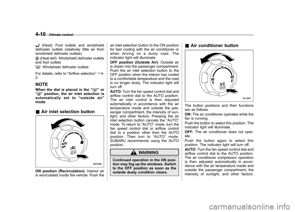
Air conditioner button
The button positions and their functions
are as follows. ON: The air conditioner operates while the
fan is running.
Push the button to select this position. The
indicator light will illuminate. OFF: The air conditioner does not oper-
ate.
Push the button again to select this
position. The indicator light will turn off. AUTO: Turn the fan speed control dial and
airflow control dial to the AUTO position.
The air conditioner compressor operation
is then adjusted automatically in accor-
dance with the air temperature inside and
outside the passenger compartment, the
intensity of sunlight, and other factors.
Page 212 of 402
&Use with a cigarette lighter
(dealer option)
To use the accessory power outlet as a
cigarette lighter socket, purchase the
cigarette lighter plug, which is an optional
accessory.
A cigarette lighter plug is available from
your SUBARU dealer.
The cigarette lighter operates only when
the ignition switch is in the “ON ”or “Acc ”
position.
To use the cigarette lighter, push in the
knob and wait a few moments. It will
automatically spring up when ready foruse.
WARNING
To avoid being burned, never grasp
the lighter by the end with the
heating element. Doing so could
result in injury and could also
damage the heating element.
CAUTION
. Do not hold the lighter pushed in,
because it will overheat.
. Do not use a non-genuine cigar-
ette lighter plug in the socket.
Doing so may cause a short- circuit and overheating, resulting
in a fire.
. If the socket is ever used for a
plug-in accessory such as a cell
phone, that may damage the
portion of the socket ’s internal
mechanism that causes a cigar-
ette lighter plug to “pop out ”
after its lighter element is heated.
Therefore, do not place a cigar-
ette lighter plug in a socket that
has been used, even once, to
power a plug-in accessory. Doing
so may cause the plug to stick
and overheat, creating a potential
fire hazard. Ashtray (if equipped)
CAUTION
Do not use ashtrays as waste re-
ceptacles or leave a lighted cigarette
in an ashtray. This could cause afire.
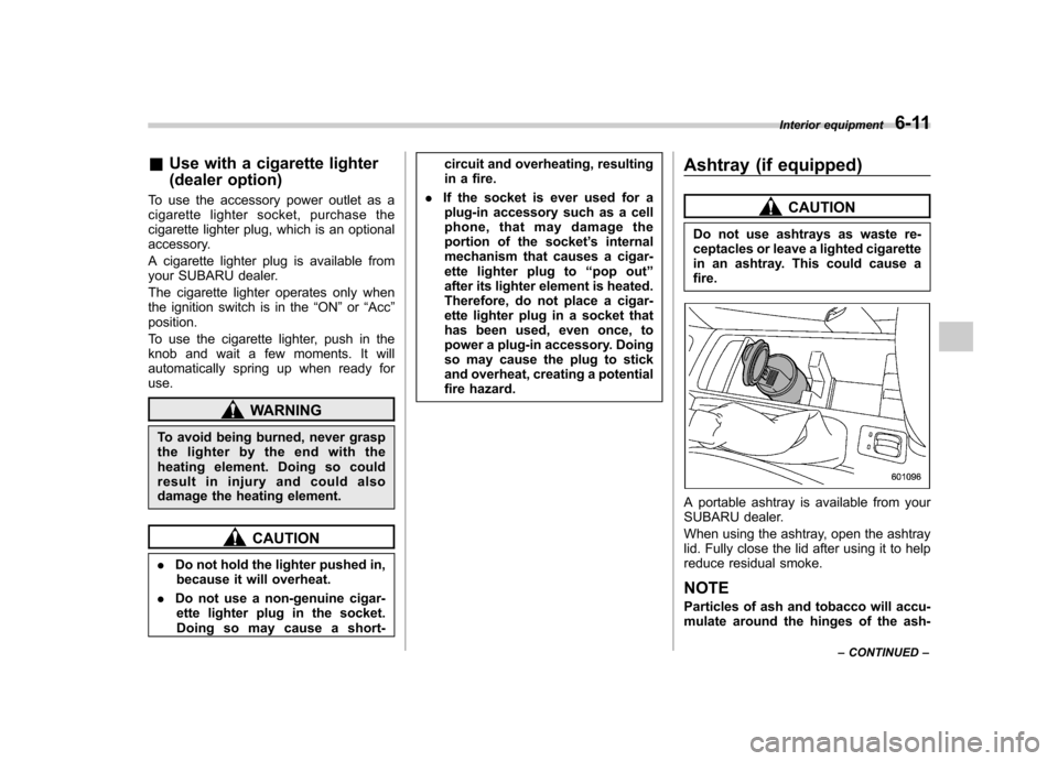
A portable ashtray is available from your
SUBARU dealer.
When using the ashtray, open the ashtray
lid. Fully close the lid after using it to help
reduce residual smoke. NOTE
Particles of ash and tobacco will accu-
mulate around the hinges of the ash- Interior equipment
6-11
– CONTINUED –
Page 214 of 402
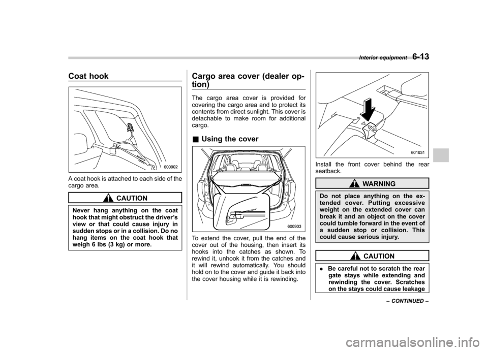
Coat hook
A coat hook is attached to each side of the
cargo area.
CAUTION
Never hang anything on the coat
hook that might obstruct the driver ’s
view or that could cause injury in
sudden stops or in a collision. Do no
hang items on the coat hook that
weigh 6 lbs (3 kg) or more. Cargo area cover (dealer op- tion)
The cargo area cover is provided for
covering the cargo area and to protect its
contents from direct sunlight. This cover is
detachable to make room for additionalcargo. &
Using the cover
To extend the cover, pull the end of the
cover out of the housing, then insert its
hooks into the catches as shown. To
rewind it, unhook it from the catches and
it will rewind automatically. You should
hold on to the cover and guide it back into
the cover housing while it is rewinding.
Install the front cover behind the rear seatback.
WARNING
Do not place anything on the ex-
tended cover. Putting excessive
weight on the extended cover can
break it and an object on the cover
could tumble forward in the event of
a sudden stop or collision. This
could cause serious injury.
CAUTION
. Be careful not to scratch the rear
gate stays while extending and
rewinding the cover. Scratches
on the stays could cause leakage Interior equipment
6-13
– CONTINUED –