tires SUBARU FORESTER 2011 SH / 3.G Service Manual
[x] Cancel search | Manufacturer: SUBARU, Model Year: 2011, Model line: FORESTER, Model: SUBARU FORESTER 2011 SH / 3.GPages: 446, PDF Size: 15.93 MB
Page 383 of 446
11-36Maintenance and service
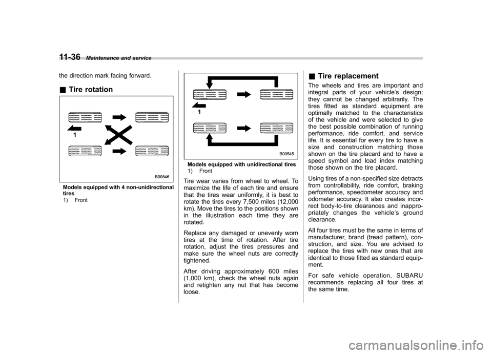
the direction mark facing forward. & Tire rotation
Models equipped with 4 non-unidirectional tires
1) Front
Models equipped with unidirectional tires
1) Front
Tire wear varies from wheel to wheel. To
maximize the life of each tire and ensure
that the tires wear uniformly, it is best to
rotate the tires every 7,500 miles (12,000
km). Move the tires to the positions shown
in the illustration each time they arerotated.
Replace any damaged or unevenly worn
tires at the time of rotation. After tire
rotation, adjust the tires pressures and
make sure the wheel nuts are correctlytightened.
After driving approximately 600 miles
(1,000 km), check the wheel nuts again
and retighten any nut that has becomeloose. &
Tire replacement
The wheels and tires are important and
integral parts of your vehicle ’s design;
they cannot be changed arbitrarily. The
tires fitted as standard equipment are
optimally matched to the characteristics
of the vehicle and were selected to give
the best possible combination of running
performance, ride comfort, and service
life. It is essential for every tire to have a
size and construction matching those
shown on the tire placard and to have a
speed symbol and load index matching
those shown on the tire placard.
Using tires of a non-specified size detracts
from controllability, ride comfort, braking
performance, speedometer accuracy and
odometer accuracy. It also creates incor-
rect body-to-tire clearances and inappro-
priately changes the vehicle ’s ground
clearance.
All four tires must be the same in terms of
manufacturer, brand (tread pattern), con-
struction, and size. You are advised to
replace the tires with new ones that are
identical to those fitted as standard equip-ment.
For safe vehicle operation, SUBARU
recommends replacing all four tires at
the same time.
Page 384 of 446
WARNING
. All four tires must be the same in
terms of manufacturer, brand
(tread pattern), construction, de-
gree of wear, speed symbol, load
index and size. Mixing tires of
different types, sizes or degrees
of wear can result in damage tovehicle ’s powertrain. Use of dif-
ferent types or sizes of tires can
also dangerously reduce con-
trollability and braking perfor-
mance and can lead to an acci-dent.
. Use only radial tires. Do not use
radial tires together with belted
bias tires and/or bias-ply tires.
Doing so can dangerously re-
duce controllability, resulting in
an accident.
& Wheel replacement
When replacing wheels due, for example,
to damage, make sure the replacement
wheels match the specifications of the
wheels that are fitted as standard equip-
ment. Replacement wheels are available
from SUBARU dealers.WARNING
Use only those wheels that are
specified for your vehicle. Wheels
not meeting specifications could
interfere with brake caliper opera-
tion and may cause the tires to rub
against the wheel well housing dur-
ing turns. The resulting loss of
vehicle control could lead to anaccident.
NOTE
When any of the wheels are removed
and replaced for tire rotation or to
change a flat tire, always check the
tightness of the wheel nuts after driv-
ing approximately 600 miles (1,000 km).
If any nut is loose, tighten it to the
specified torque. &
Wheel covers (if equipped)
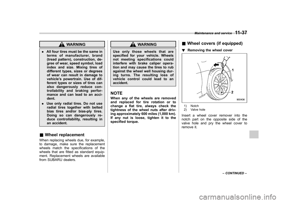
! Removing the wheel cover
1) Notch
2) Valve hole
Insert a wheel cover remover into the
notch part on the opposite side of the
valve hole and pry the wheel cover to
remove it. Maintenance and service
11-37
– CONTINUED –
Page 400 of 446
Specifications..................................................... 12-2
Dimensions ........................................................ 12-2
Engine ............................................................... 12-3
Electrical system ................................................ 12-3
Fuel ................................................................... 12-4
Engine oil .......................................................... 12-5
Manual transmission, front differential and rear differential gear oil ........................................... 12-8
Fluids ................................................................ 12-9
Engine coolant ................................................... 12-9 Tires
................................................................ 12-10
Wheel alignment .............................................. 12-10
Fuses and circuits ........................................... 12-11
Fuse panel located in the passenger compartment ................................................. 12-11
Fuse panel located in the engine compartment ................................................. 12-13
Bulb chart ......................................................... 12-15
Vehicle identification ....................................... 12-18Specifications
12
Page 409 of 446
12-10Specifications
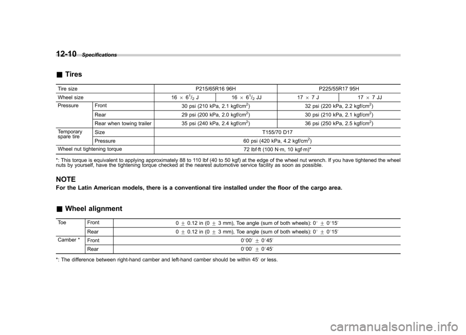
&Tires
Tire size P215/65R16 96H P225/55R17 95H
Wheel size 1666
1/2J1 66 61/2JJ 17 67J 17 67JJ
Pressure Front 30 psi (210 kPa, 2.1 kgf/cm2) 32 psi (220 kPa, 2.2 kgf/cm2)
Rear 29 psi (200 kPa, 2.0 kgf/cm2) 30 psi (210 kPa, 2.1 kgf/cm2)
Rear when towing trailer 35 psi (240 kPa, 2.4 kgf/cm2) 36 psi (250 kPa, 2.5 kgf/cm2)
Temporary
spare tire Size
T155/70 D17
Pressure 60 psi (420 kPa, 4.2 kgf/cm
2)
Wheel nut tightening torque 72 lbf·ft (100 N·m, 10 kgf·m)*
*: This torque is equivalent to applying approximately 88 to 110 lbf (40 to 50 kgf) at the edge of the wheel nut wrench. If you have tightened the wheel
nuts by yourself, have the tightening torque checked at the nearest automotive service facility as soon as possible.
NOTE
For the Latin American models, there is a conventional tire installed under the floor of the cargo area. & Wheel alignment
Toe Front 0+ 0.12 in (0 +3 mm), Toe angle (sum of both wheels): 0 8+0815 ’
Rear 0 +0.12 in (0 +3 mm), Toe angle (sum of both wheels): 0 8+0815 ’
Camber * Front 0800 ’+ 0845 ’
Rear 0
800 ’+ 0845 ’
*: The difference between right-hand camber and left-hand camber should be within 45 ’or less.
Page 418 of 446
For U.S.A............................................................ 13-2
Tire information .................................................. 13-2
Tire labeling ....................................................... 13-2
Recommended tire inflation pressure .................. 13-4
Glossary of tire terminology ............................... 13-5
Tire care –maintenance and safety practices ...... 13-9
Vehicle load limit –how to determine ................ 13-10
Determining compatibility of tire and vehicle load capacities ............................................... 13-13 Adverse safety consequences of overloading
on handling and stopping and on tires ........... 13-13
Steps for Determining Correct Load Limit ......... 13-13
Uniform tire quality grading standards .......... 13-14
Treadwear ....................................................... 13-14
Traction AA, A, B, C ......................................... 13-14
Temperature A, B, C ......................................... 13-15
Reporting safety defects (U.S.A.) ................... 13-15
Consumer information and Reporting safety defects
13
Page 419 of 446
13-2Consumer information and Reporting safety defects
For U.S.A.
The following information has been
compiled according to Code of
Federal Regulations “Title 49, Part
575 ”. Tire information &
Tire labeling
Many markings (e.g. Tire size, Tire
Identification Number or TIN) are
placed on the sidewall of a tire by
tire manufacturers. These markings
can provide you with useful infor-
mation on the tire. ! Tire size
Your vehicle comes equipped with
P-Metric tire size. It is important to
understand the sizing system in
selecting the proper tire for your
vehicles. Here is a brief review of
the tire sizing system with a break-
down of its individual elements. ! P Metric
With the P-Metric system, Section
Width is measured in millimeters.
To convert millimeters into inches,
divide by 25.4. The Aspect Ratio
(Section Height divided by Section
Width) helps provide more dimen-
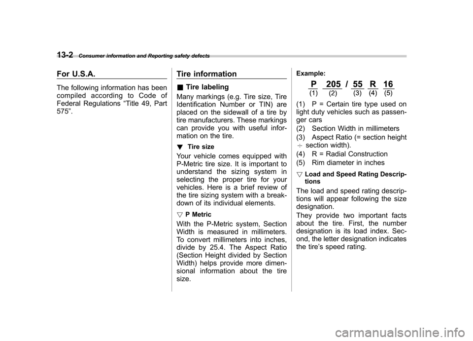
sional information about the tiresize. Example:
(1) P = Certain tire type used on
light duty vehicles such as passen-
ger cars
(2) Section Width in millimeters
(3) Aspect Ratio (= section height 7
section width).
(4) R = Radial Construction
(5) Rim diameter in inches ! Load and Speed Rating Descrip- tions
The load and speed rating descrip-
tions will appear following the size designation.
They provide two important facts
about the tire. First, the number
designation is its load index. Sec-
ond, the letter designation indicates
the tire ’s speed rating.
Page 420 of 446
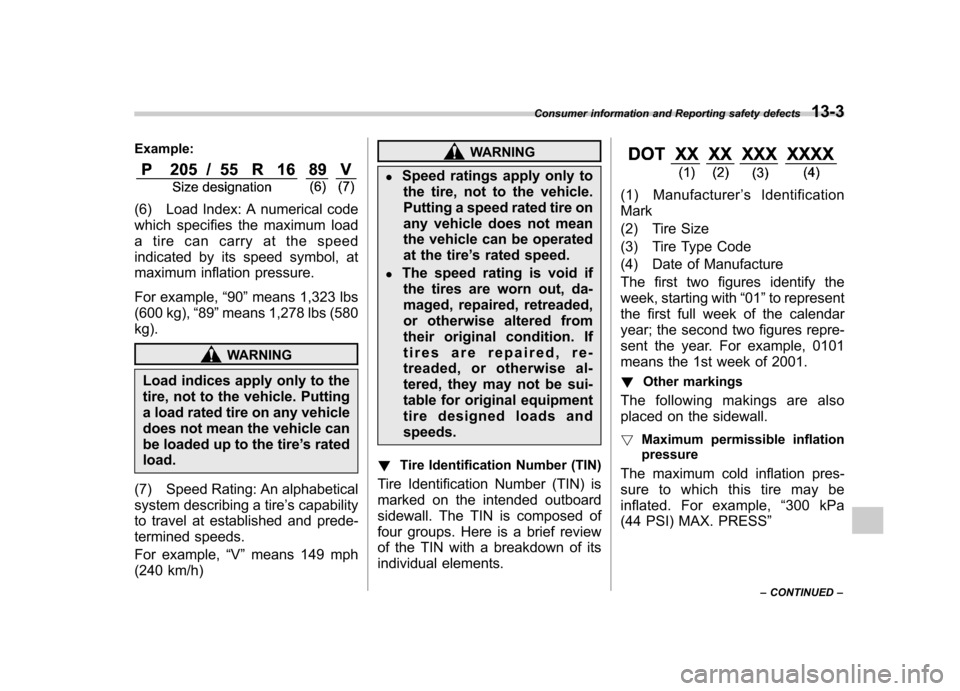
Example:
(6) Load Index: A numerical code
which specifies the maximum load
a tire can carry at the speed
indicated by its speed symbol, at
maximum inflation pressure.
For example,“90 ”means 1,323 lbs
(600 kg), “89 ”means 1,278 lbs (580
kg).
WARNING
Load indices apply only to the
tire, not to the vehicle. Putting
a load rated tire on any vehicle
does not mean the vehicle can
be loaded up to the tire ’s rated
load.
(7) Speed Rating: An alphabetical
system describing a tire ’s capability
to travel at established and prede-
termined speeds.
For example, “V ” means 149 mph
(240 km/h)
WARNING
. Speed ratings apply only to
the tire, not to the vehicle.
Putting a speed rated tire on
any vehicle does not mean
the vehicle can be operated
at the tire ’s rated speed.
. The speed rating is void if
the tires are worn out, da-
maged, repaired, retreaded,
or otherwise altered from
their original condition. If
tires are repaired, re-
treaded, or otherwise al-
tered, they may not be sui-
table for original equipment
tire designed loads andspeeds.
! Tire Identification Number (TIN)
Tire Identification Number (TIN) is
marked on the intended outboard
sidewall. The TIN is composed of
four groups. Here is a brief review
of the TIN with a breakdown of its
individual elements.
(1) Manufacturer ’s Identification
Mark
(2) Tire Size
(3) Tire Type Code
(4) Date of Manufacture
The first two figures identify the
week, starting with “01 ”to represent
the first full week of the calendar
year; the second two figures repre-
sent the year. For example, 0101
means the 1st week of 2001.
! Other markings
The following makings are also
placed on the sidewall. ! Maximum permissible inflation
pressure
The maximum cold inflation pres-
sure to which this tire may be
inflated. For example, “300 kPa
(44 PSI) MAX. PRESS ”
Consumer information and Reporting safety defects
13-3
– CONTINUED –
Page 421 of 446
13-4Consumer information and Reporting safety defects
!Maximum load rating
The load rating at the maximum
permissible weight load for this tire.
For example, “MAX. LOAD 580 kg
(1279 LBS) @ 300 kPa (44 PSI)
MAX. PRESS. ”
WARNING
Maximum load rating applies
only to the tire, not to the
vehicle. Putting a load rated
tire on any vehicle does not
mean the vehicle can be
loaded up to the tire ’s rated
load.
! Construction type
Applicable construction of this tire.
For example, “TUBELESS STEEL
BELTED RADIAL ”
! Construction
The generic name of each cord
material used in the plies (both
sidewall and tread area) of this tire.
For example, “PLIES: TREAD 2 STEEL + 2 POLYESTER SIDE-
WALL 2 POLYESTER
”
! Uniform Tire Quality Grading (UTQG)
For details, refer to “Uniform tire
quality grading standards ”F 13-14 .
& Recommended tire inflation pressure
! Recommended cold tire infla-
tion pressure
For recommended cold tire inflation
pressure for your vehicle ’s tires,
refer to “Tires ”F 12-10 .
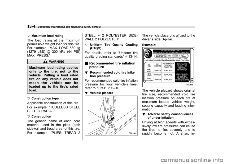
! Vehicle placard
The vehicle placard is affixed to the driver ’s side B-pillar.
Example:
The vehicle placard shows original
tire size, recommended cold tire
inflation pressure on each tire at
maximum loaded vehicle weight,
seating capacity and loading infor-mation. ! Adverse safety consequences
of under-inflation
Driving at high speeds with exces-
sively low tire pressures can cause
the tires to flex severely and to
rapidly become hot. A sharp in-
Page 422 of 446
crease in temperature could cause
tread separation, and failure of the
tire(s). Possible resulting loss of
vehicle control could lead to anaccident. !Measuring and adjusting air
pressure to achieve proper in-
flation
Check and, if necessary, adjust the
pressure of each tire (including the
spare) at least once a month and
before any long journey. Check the
tire pressures when the tires are
cold. Use a pressure gauge to
adjust the tire pressures to the
specific values. Driving even a
short distance warms up the tires
and increases the tire pressures.
Also, the tire pressures are affected
by the outside temperature. It is
best to check tire pressure out-
doors before driving the vehicle.
When a tire becomes warm, the air
inside it expands, causing the tire
pressure to increase. Be careful not
to mistakenly release air from a
warm tire to reduce its pressure. &
Glossary of tire terminology
. Accessory weight
The combined weight (in excess of
those standard items which may be
replaced) of automatic transmis-
sion, power steering, power brakes,
power windows, power seats, radio,
and heater, to the extent that these
items are available as factory-in-
stalled equipment (whether in-
stalled or not). . Bead
The part of the tire that is made of
steel wires, wrapped or reinforced
by ply cords and that is shaped to fit
the rim.. Bead separation
A breakdown of the bond between
components in the bead.. Bias ply tire
A pneumatic tire in which the ply
cords that extend to the beads are
laid at alternate angles substantially
less than 90 degrees to the center-
line of the tread. . Carcass
The tire structure, except tread and sidewall rubber which, when in-
flated, bears the load. .
Chunking
The breaking away of pieces of the
tread or sidewall.. Cold tire pressure
The pressure in a tire that has been
driven less than 1 mile or has been
standing for three hours or more.. Cord
The strands forming the plies in the tire. . Cord separation
The parting of cords from adjacent
rubber compounds.. Cracking
Any parting within the tread, side-
wall, or inner liner of the tire
extending to cord material. . Curb weight
The weight of a motor vehicle with
standard equipment including the
maximum capacity of fuel, oil and
coolant, and if so equipped, air
conditioning and additional weight
optional engine.
Consumer information and Reporting safety defects
13-5
– CONTINUED –
Page 426 of 446

Table 1—Occupant loading and distribution for vehicle normal load for
various designated seating capacities
Designated seating
capacity, number of
occupants Vehicle normal load,
number of occupants Occupant distribution in a
normally loaded vehicle
2 through 4 2 2 in front.
5 through 10 3 2 in front, 1 in second seat.
11 through 15 5 2 in front, 1 in second
seat, 1 in third seat, 1 in
fourth seat.
16 through 22 7 2 in front, 2 in second
seat, 2 in third seat, 1 in
fourth seat.&
Tire care –maintenance and
safety practices
. Check on a daily basis that the
tires are free from serious damage,
nails, and stones. At the same time,
check the tires for abnormal wear. . Inspect the tire tread regularly
and replace the tires before their
tread wear indicators become visi-
ble. When a tire ’s tread wear
indicator becomes visible, the tire
is worn beyond the acceptable limit
and must be replaced immediately.
With a tire in this condition, driving
at even low speeds in wet weather
can cause the vehicle to hydro-
plane. Possible resulting loss of
vehicle control can lead to anaccident. . To maximize the life of each tire
and ensure that the tires wear
uniformly, it is best to rotate the
tires every 7,500 miles (12,000 km).
For information about the tire rota-
tion order, refer to “Tire rotation ”
F 11-36 .
Consumer information and Reporting safety defects
13-9
– CONTINUED –