heater SUBARU FORESTER 2011 SH / 3.G Owners Manual
[x] Cancel search | Manufacturer: SUBARU, Model Year: 2011, Model line: FORESTER, Model: SUBARU FORESTER 2011 SH / 3.GPages: 446, PDF Size: 15.93 MB
Page 7 of 446

4
Mark Name
Hazard warning flasher
Engine hood
Seat heater
Child restraint top tether an- chorages
Child restraint lower an- chorages
Horn
Wiper intermittent
Windshield washer
Windshield wiper mist (for
single wipe)
Rear window wiper
Rear window washerMark Name
Lights
Tail lights, license plate light
and instrument panel illumi- nation
Headlights
Turn signal
Illumination brightness
Fan speed
Instrument panel outlets
Instrument panel outlets and
foot outlets
Foot outlets
Windshield defroster and foot outlets
Windshield defrosterMark Name
Rear window defogger/Out-
side mirror defogger
Air recirculation
Engine oil
Washer
Door lock (Transmitter)
Door unlock (Transmitter)
Rear gate (Transmitter)
Page 26 of 446

Front seats........................................................... 1-2
Manual seat ........................................................ 1-3
Power seat (driver ’s seat –if equipped) ... ............ 1-4
Head restraint adjustment .................................... 1-5
Active head restraint ........................................... 1-6
Seat heater (if equipped) .................................... 1-6
Rear seats ............................................................ 1-7
Armrest .............................................................. 1-8
Head restraint adjustment .................................... 1-8
Reclining the seatback (if equipped) ................... 1-10
Folding down the rear seatback .......................... 1-10
Seatbelts ............................................................. 1-12
Seatbelt safety tips ............................................. 1-12
Emergency Locking Retractor (ELR) ................... 1-13
Automatic/Emergency Locking Retractor (A/ELR) ............................................................ 1-13
Seatbelt warning light and chime ........................ 1-13
Fastening the seatbelt ........................................ 1-13
Seatbelt maintenance ......................................... 1-19
Front seatbelt pretensioners ............................. 1-20
System monitors ................................................ 1-21 System servicing
............................................... 1-21
Precautions against vehicle modification ............ 1-21
Child restraint systems ..................................... 1-22
Where to place a child restraint system .............. 1-23
Choosing a child restraint system ...................... 1-24
Installing child restraint systems with A/ELR seatbelt ........................................................... 1-24
Installing a booster seat ..................................... 1-27
Installation of child restraint systems by use of lower and tether anchorages (LATCH) .............. 1-29
Top tether anchorages ....................................... 1-31
*SRS airbag (Supplemental Restraint System airbag) ................................................ 1-33
Models with SRS airbags and lap/shoulder restraints for driver, front passenger, and
window-side rear passengers . .......................... 1-33
SUBARU advanced frontal airbag system ........... 1-37
SRS side airbag and SRS curtain airbag ............. 1-47
SRS airbag system monitors .............................. 1-57
SRS airbag system servicing ... .......................... 1-58
Precautions against vehicle modification ............ 1-59
Seat, seatbelt and SRS airbags1
Page 31 of 446
1-6Seat, seatbelt and SRS airbags
pants.
. All occupants, including the dri-
ver, should not operate a vehicle
or sit in a vehicle ’s seat until the
head restraints are placed in their
proper positions in order to mini-
mize the risk of neck injury in the
event of a crash.
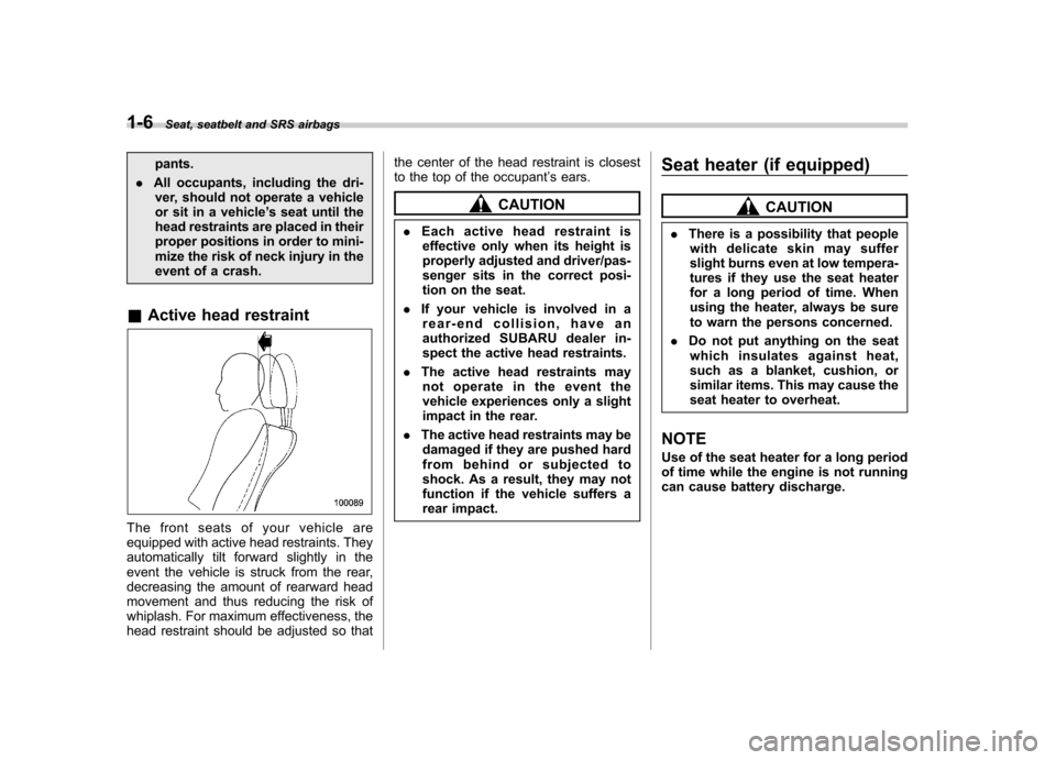
& Active head restraint
The front seats of your vehicle are
equipped with active head restraints. They
automatically tilt forward slightly in the
event the vehicle is struck from the rear,
decreasing the amount of rearward head
movement and thus reducing the risk of
whiplash. For maximum effectiveness, the
head restraint should be adjusted so that the center of the head restraint is closest
to the top of the occupant
’s ears.
CAUTION
. Each active head restraint is
effective only when its height is
properly adjusted and driver/pas-
senger sits in the correct posi-
tion on the seat.
. If your vehicle is involved in a
rear-end collision, have an
authorized SUBARU dealer in-
spect the active head restraints.
. The active head restraints may
not operate in the event the
vehicle experiences only a slight
impact in the rear.
. The active head restraints may be
damaged if they are pushed hard
from behind or subjected to
shock. As a result, they may not
function if the vehicle suffers a
rear impact. Seat heater (if equipped)CAUTION
. There is a possibility that people
with delicate skin may suffer
slight burns even at low tempera-
tures if they use the seat heater
for a long period of time. When
using the heater, always be sure
to warn the persons concerned.
. Do not put anything on the seat
which insulates against heat,
such as a blanket, cushion, or
similar items. This may cause the
seat heater to overheat.
NOTE
Use of the seat heater for a long period
of time while the engine is not running
can cause battery discharge.
Page 32 of 446
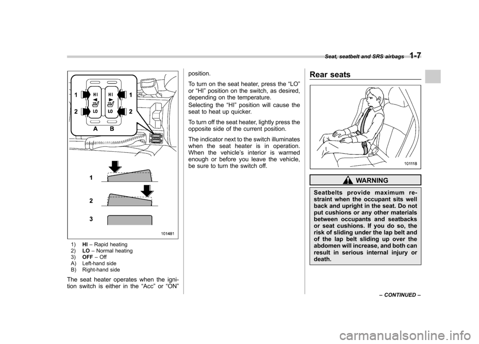
1)HI–Rapid heating
2) LO–Normal heating
3) OFF –Off
A) Left-hand side
B) Right-hand side
The seat heater operates when the igni-
tion switch is either in the “Acc ”or “ON ” position.
To turn on the seat heater, press the
“LO ”
or “HI ”position on the switch, as desired,
depending on the temperature.
Selecting the “HI ”position will cause the
seat to heat up quicker.
To turn off the seat heater, lightly press the
opposite side of the current position.
The indicator next to the switch illuminates
when the seat heater is in operation.
When the vehicle ’s interior is warmed
enough or before you leave the vehicle,
be sure to turn the switch off. Rear seats
WARNING
Seatbelts provide maximum re-
straint when the occupant sits well
back and upright in the seat. Do not
put cushions or any other materials
between occupants and seatbacks
or seat cushions. If you do so, the
risk of sliding under the lap belt and
of the lap belt sliding up over the
abdomen will increase, and both can
result in serious internal injury ordeath. Seat, seatbelt and SRS airbags
1-7
– CONTINUED –
Page 149 of 446
3-38Instruments and controls
displayed.
4. Releasing the button for 3 seconds will
exit the zone setting mode. ! Compass calibration
1. For optimum calibration, switch off all
nonessential electrical accessories (rear
window defogger, heater/air conditioning
system, spotlight, etc.) and ensure all
doors are shut.
2. Drive to an open, level area away from
large metallic objects or structures and
make certain the ignition switch is in the“ ON ”position.
3. Press and hold the right button for 6 - 7
seconds then release, and the compass
will enter the calibration mode. “CAL ”and
direction will be displayed.
4. Drive slowly in a circle until “CAL ”
disappears from the display (approxi-
mately two to three circles). The compass
is now calibrated.
5. Further calibration may be necessary
should outside influences cause the mirror
to read inaccurately. You will know that
this has occurred if your compass begins
to read in only limited directions. Should
you encounter this situation, return to step
one of the above procedure and recali-
brate the mirror. &
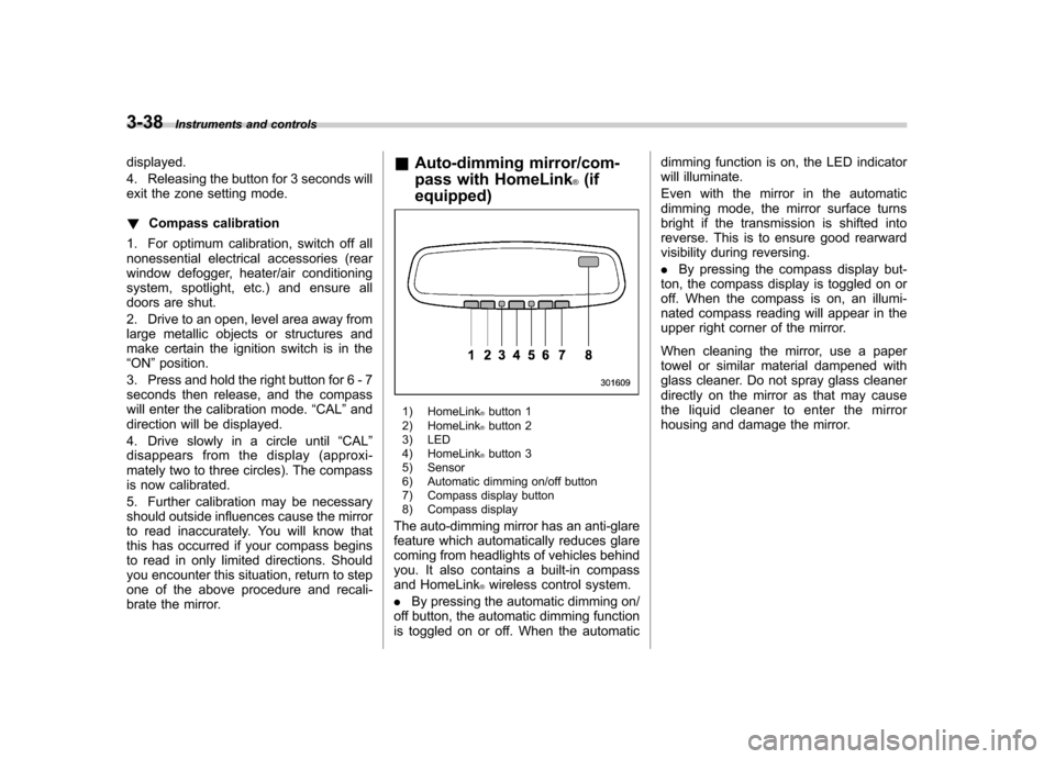
Auto-dimming mirror/com-
pass with HomeLink
®(if
equipped)
1) HomeLink®button 1
2) HomeLink®button 2
3) LED
4) HomeLink
®button 3
5) Sensor
6) Automatic dimming on/off button
7) Compass display button
8) Compass display
The auto-dimming mirror has an anti-glare
feature which automatically reduces glare
coming from headlights of vehicles behind
you. It also contains a built-in compass
and HomeLink
®wireless control system.
. By pressing the automatic dimming on/
off button, the automatic dimming function
is toggled on or off. When the automatic dimming function is on, the LED indicator
will illuminate.
Even with the mirror in the automatic
dimming mode, the mirror surface turns
bright if the transmission is shifted into
reverse. This is to ensure good rearward
visibility during reversing. .
By pressing the compass display but-
ton, the compass display is toggled on or
off. When the compass is on, an illumi-
nated compass reading will appear in the
upper right corner of the mirror.
When cleaning the mirror, use a paper
towel or similar material dampened with
glass cleaner. Do not spray glass cleaner
directly on the mirror as that may cause
the liquid cleaner to enter the mirror
housing and damage the mirror.
Page 160 of 446

Ventilator.............................................................. 4-2
Airflow selection ................................................. 4-2
Center and side ventilators .................................. 4-3
Manual climate control system (if equipped) ..................................................... 4-3
Control panel ...................................................... 4-3
Heater operation ................................................. 4-5
Air conditioner operation ..................................... 4-7
Automatic climate control system (if equipped) ..................................................... 4-8
Type A ................................................................ 4-8
Type B ............................................................... 4-13
Temperature sensors .......................................... 4-17 Operating tips for heater and air
conditioner ...................................................... 4-17
Cleaning ventilation grille ................................... 4-17
Efficient cooling after parking in direct sunlight ........................................................... 4-17
Lubrication oil circulation in the refrigerant circuit .............................................................. 4-18
Checking air conditioning system before summer season ............................................................ 4-18
Cooling and dehumidifying in high humidity and low temperature weather conditions ................. 4-18
Air conditioner compressor shut-off when engine is heavily loaded .............................................. 4-18
Refrigerant for your climate control system ... ..... 4-18
Air filtration system ........................................... 4-18
Replacing an air filter ......................................... 4-19Climate control
4
Page 164 of 446
Place the air inlet selection button to the
OFF position when the interior has cooled
to a comfortable temperature and the road
is no longer dusty.
WARNING
Continued operation with the air
inletselectionbuttonintheON
position may fog up the windows.
Switch to the OFF position as soon
as the outside dusty conditionclears.
& Heater operation
NOTE . Models with air conditioner system:
When the “
”or “”position is
selected, the air conditioner compres-
sor automatically operates regardless
of the position of the air conditioner
button to defog the windshield more
quickly. At the same time, the air inlet
selection is automatically switched to
the OFF position (outside air). How-
ever, the air conditioner indicator light
does not illuminate at this time.. When defrosting, defogging or heat-
ing, warm air is also emitted from the
right and left air outlets. To stop warm
airflow from these outlets, turn the corresponding thumb wheel down. !
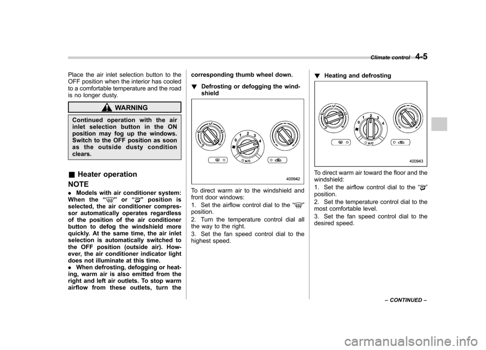
Defrosting or defogging the wind- shield
To direct warm air to the windshield and
front door windows:
1. Set the airflow control dial to the “
”
position.
2. Turn the temperature control dial all
the way to the right.
3. Set the fan speed control dial to the
highest speed. !
Heating and defrosting
To direct warm air toward the floor and the windshield:
1. Set the airflow control dial to the “
”
position.
2. Set the temperature control dial to the
most comfortable level.
3. Set the fan speed control dial to the
desired speed. Climate control
4-5
– CONTINUED –
Page 176 of 446
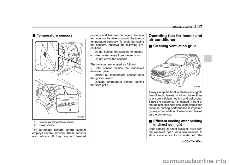
&Temperature sensors
1) Interior air temperature sensor
2) Solar sensor
The automatic climate control system
employs several sensors. These sensors
are delicate. If they are not treated properly and become damaged, the sys-
tem may not be able to control the interior
temperature correctly. To avoid damaging
the sensors, observe the following pre-cautions. –
Do not subject the sensors to impact.
– Keep water away from the sensors.
– Do not cover the sensors.
The sensors are located as follows.– Solar sensor: beside the windshield
defroster grille.– Interior air temperature sensor: near
the ignition switch.– Outside temperature sensor: behind
the front grille. Operating tips for heater and
air conditioner &
Cleaning ventilation grille
Always keep the front ventilation inlet grille
free of snow, leaves, or other obstructions
to ensure efficient heating and defrosting.
Since the condenser is located in front of
the radiator, this area should be kept clean
because cooling performance is impaired
by any accumulation of insects and leaves
on the condenser. &Efficient cooling after parking
in direct sunlight
After parking in direct sunlight, drive with
the windows open for a few minutes to
allow outside air to circulate into the Climate control
4-17
– CONTINUED –
Page 211 of 446
5-32Audio
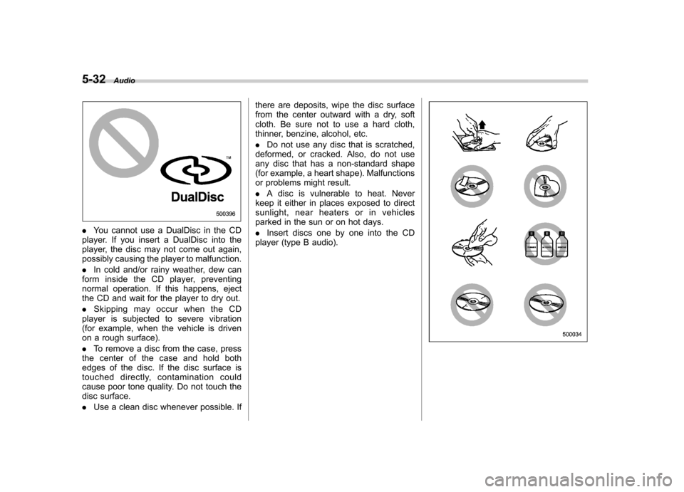
.You cannot use a DualDisc in the CD
player. If you insert a DualDisc into the
player, the disc may not come out again,
possibly causing the player to malfunction. . In cold and/or rainy weather, dew can
form inside the CD player, preventing
normal operation. If this happens, eject
the CD and wait for the player to dry out. . Skipping may occur when the CD
player is subjected to severe vibration
(for example, when the vehicle is driven
on a rough surface). . To remove a disc from the case, press
the center of the case and hold both
edges of the disc. If the disc surface is
touched directly, contamination could
cause poor tone quality. Do not touch the
disc surface. . Use a clean disc whenever possible. If there are deposits, wipe the disc surface
from the center outward with a dry, soft
cloth. Be sure not to use a hard cloth,
thinner, benzine, alcohol, etc. .
Do not use any disc that is scratched,
deformed, or cracked. Also, do not use
any disc that has a non-standard shape
(for example, a heart shape). Malfunctions
or problems might result. . A disc is vulnerable to heat. Never
keep it either in places exposed to direct
sunlight, near heaters or in vehicles
parked in the sun or on hot days. . Insert discs one by one into the CD
player (type B audio).
Page 270 of 446

transmitter within a few seconds immedi-
ately following remote engine start shut-down. &Pre-heating or pre-cooling
the interior of the vehicle
Before exiting the vehicle, set the tem-
perature controls to the desired setting
and operation. After the system starts the
vehicle, the heater or air-conditioning will
activate and heat or cool the interior to
your setting. & Service mode
In service mode, the remote start function
is temporarily disabled to prevent the
system from unexpectedly starting the
engine while being serviced. ! To engage the service mode
Turn the ignition switch to the “ON ”
position, depress and hold the brake
pedal, then press and release the “
”
button on the remote control transmitter
three times. The system will pause for 1
second and then flash the turn signal
lights and honk the horn three times
indicating that the system is in service
mode. When attempting to activate the
remote start system while in service
mode, the turn signal lights will flash and
the horn will honk two times and will not start. !
To disengage the service mode
Turn the ignition switch to the “ON ”
position, depress and hold the brake
pedal, then press and release the “
”
button on the remote control transmitter
three times. The system will pause for 1
second and flash the turn signal lights 1
time indicating that the system has exited
service mode. NOTE
When taking your vehicle in for service,
it is recommended that you inform the
service personnel that your vehicle is
equipped with a remote control startsystem. & Remote transmitter program-
ming and programmable fea-
ture option
New transmitters can be programmed to
the engine starter system in the event that
remote transmitters are lost, stolen or
damaged. The remote engine start system
also has one programmable feature that
can be adjusted for user preference.
The remote engine starter system can be
programmed to either make an audible
horn chirp upon remote start activation or
not. Remote transmitter programming and feature programming can be adjusted
using the following procedure.
1. Open the driver
’s door (the driver ’s
door must remain opened throughout the
entire process).
2. Insert the key into the vehicle ’s ignition
switch and turn to the “ON ”position.
3. Locate the small black programming
button behind the fuse box cover, on the
driver ’s side left under the dashboard
panel.
4. Press and hold the black programming
button for 10 to 15 seconds. The horn will
honk and the turn signal lights will flash
three times to indicate that the system has
entered programming mode. At this point
you can proceed to either step 5 or step 6.
5. To program a remote transmitter:
press and release the “
”button on each
transmitter. The horn will honk and the
turn signal lights will flash one time to
indicate a successful transmitter learn
each time the “
”button is pressed. You
can program up to eight transmitters.
6. To toggle the Horn Confirmation chirps
ON/OFF: press and release the brake to
toggle the feature. The horn will chirp and
the turn signal lights will flash one time to
indicate Confirmation Horn Chirps are“ OFF ”. The horn will honk and the turn
signal lights will flash 2 times to indicate
Confirmation Horn Chirps are “ON ”.
Starting and operating
7-11
– CONTINUED –