sport mode SUBARU FORESTER 2011 SH / 3.G Owners Manual
[x] Cancel search | Manufacturer: SUBARU, Model Year: 2011, Model line: FORESTER, Model: SUBARU FORESTER 2011 SH / 3.GPages: 446, PDF Size: 15.93 MB
Page 24 of 446

&Warning and indicator lights
Mark Name Page
Seatbelt warning light 3-13
Front passenger ’s seat-
belt warning light 3-13
SRS airbag system
warning light3-15
/Front passenger
’s fron-
tal airbag ON indicator 3-15
/Front passenger
’s fron-
tal airbag OFF indicator 3-15
CHECK ENGINE
warning light/Malfunction
indicator lamp3-16
Coolant temperature low
indicator light (if
equipped)/Coolant tem-
perature high warning
light (if equipped)3-16
Charge warning light 3-17
Oil pressure warning light
3-17
AT OIL TEMP warning
light (AT models)3-18Mark Name Page
/ABS warning light 3-19
/Brake system warning light
3-20
Door open warning light 3-21
AWD warning light
(AT models)
3-21
Hill start assist warning
light (MT models)
3-21
Vehicle Dynamics Con-
trol warning light/Vehicle
Dynamics Control op-
eration indicator light3-22
Vehicle Dynamics Con-
trol OFF indicator light
3-23
Turn signal indicator lights
3-25
High beam indicator light 3-25
Automatic headlight
beam leveler warning
light (models with HID headlights)3-22Mark Name Page
Front fog light indicator
light (if equipped)
3-25
Security indicator light 3-23
Headlight indicator light 3-25
Cruise control indicator light3-25
Cruise control set indi-
cator light
3-25
Low fuel warning light 3-21
Low tire pressure warn-
ing light
(U.S.-spec. models)3-18
SPORT mode indicator
light (AT models)
3-2421
Page 112 of 446
Ignition switch..................................................... 3-3
LOCK .................................................................. 3-3
Acc..................................................................... 3-4
ON...................................................................... 3-4
START ................................................................ 3-4
Key reminder chime ............................................ 3-5
Ignition switch light ............................................. 3-5
Hazard warning flasher ....................................... 3-5
Meters and gauges. ............................................. 3-6
Combination meter illumination ........................... 3-6
Canceling the function for meter/gauge needle movement upon turning on the ignition switch ............................................................... 3-6
Meter needles/gauge illumination setting (models with type A combination meter) ......................... 3-7
Speedometer ....................................................... 3-8
Odometer/Trip meter ............................................ 3-8
Tachometer ........................................................ 3-10
Fuel gauge ......................................................... 3-10
Temperature gauge (models with type A combination meter) .......................................... 3-11
ECO gauge (models with type A combination meter) .............................................................. 3-12
Warning and indicator lights ............................. 3-12
Seatbelt warning light and chime ........................ 3-13
SRS airbag system warning light ........................ 3-15
Front passenger ’s frontal airbag ON and OFF
indicators ......................................................... 3-15
CHECK ENGINE warning light/Malfunction indicator lamp .................................................. 3-16 Coolant temperature low indicator light (if
equipped)/Coolant temperature high warning
light (if equipped). ............................................ 3-16
Charge warning light .......................................... 3-17
Oil pressure warning light .................................. 3-17
AT OIL TEMP warning light (AT models) .............. 3-18
Low tire pressure warning light (U.S.-spec. models) ........................................................... 3-18
ABS warning light .............................................. 3-19
Brake system warning light ................................ 3-20
Low fuel warning light ....................................... 3-21
Hill start assist warning light (MT models) ..... ..... 3-21
Door open warning light .................................... 3-21
All-Wheel Drive warning light (AT models) ..... ..... 3-21
Automatic headlight beam leveler warning light (models with HID headlights).. .......................... 3-22
Vehicle Dynamics Control warning light/Vehicle Dynamics Control operation indicator light .. ..... 3-22
Vehicle Dynamics Control OFF indicator light ..... 3-23
Security indicator light ....................................... 3-23
SPORT mode indicator light (AT models) ............ 3-24
Select lever and gear position indicator (AT models) ........................................................... 3-24
Turn signal indicator lights ................................. 3-25
High beam indicator light ................................... 3-25
Cruise control indicator light .............................. 3-25
Cruise control set indicator light ........................ 3-25
Front fog light indicator light (if equipped) ..... ..... 3-25
Headlight indicator light ..................................... 3-25
Clock .................................................................. 3-25Instruments and controls
3
Page 124 of 446
: Coolant temperature high warning light(if equipped)
: Charge warning light
: Oil pressure warning light
: AT OIL TEMP warning light (AT models)
: Low tire pressure warning light(U.S.- spec. models)
/: ABS warning light
/: Brake system warning light
: Low fuel warning light
: Hill start assist warning light(MT models)
: Door open warning light
: AWD warning light (AT models)
: Vehicle Dynamics Control warning light/Vehicle Dynamics Control opera-
tion indicator light
: Vehicle Dynamics Control OFF indica-tor light
: SPORT mode indicator light(AT models)
: Cruise control indicator light
SET/
: Cruise control set indicator light
: Automatic headlight beam leveler warning light (models with HID head- lights)
If any lights fail to illuminate, it indicates a
burned-out bulb or a malfunction of the
corresponding system.
Consult your authorized SUBARU dealer
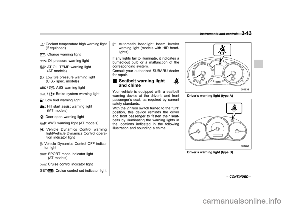
for repair. & Seatbelt warning light
and chime
Your vehicle is equipped with a seatbelt
warning device at the driver ’s and front
passenger ’s seat, as required by current
safety standards.
With the ignition switch turned to the “ON ”
position, this device reminds the driver
and front passenger to fasten their seat-
belts by illuminating the warning lights in
the locations indicated in the following
illustration and sounding a chime.Driver ’s warning light (type A)
Driver ’s warning light (type B) Instruments and controls
3-13
– CONTINUED –
Page 135 of 446
3-24Instruments and controls
equipped with an immobilizer system. It
begins flashing in the following ways. . Once approximately every 3 sec-
onds:
–Approximately 60 seconds after the
ignition switch is turned from the “ON ”
position to the “Acc ”or “LOCK ”posi-
tion – Immediately after the ignition key is
pulled out
. Twice approximately every 2 sec-
onds:
After the alarm system has been armed
for surveillance (Refer to “Arming the
system ”F 2-16.)
. Five times approximately every 2
seconds:
When the alarm system is ready to be armed. . Other flashing patterns:
The alarm system may have been trig-
gered by unauthorized intrusion or any
impact to the vehicle body. Refer to“ Tripped sensor identification ”F 2-19.
If the security indicator light does not flash,
the immobilizer system may not be func-
tioning properly. If this occurs, contact
your SUBARU dealer as soon as possible. In case an unauthorized key is used (e.g.,
an imitation key), the security indicator
light illuminates.
NOTE
Even if the security indicator light
flashes irregularly or its fuse blows
(the light does not flash if its fuse is
blown), the immobilizer system will
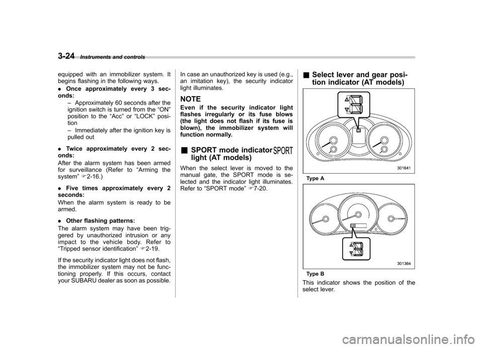
function normally. & SPORT mode indicator
light (AT models)
When the select lever is moved to the
manual gate, the SPORT mode is se-
lected and the indicator light illuminates.
Refer to “SPORT mode ”F 7-20. &
Select lever and gear posi-
tion indicator (AT models)
Type A
Type B
This indicator shows the position of the
select lever.
Page 197 of 446
5-18Audio
Satellite radio operation (if equipped)
To receive satellite radio, it is necessary to
install the SUBARU genuine satellite
receiver (optional equipment) and to enter
into a contract. For details, please contact
your SUBARU dealer. &XM
TMsatellite radio (U.S.A.
only)
XM
TMis a continental U.S. based satellite
radio service, including music, news,
sports, talk and children ’s programming.
XM
TMprovides digital quality audio and
text information, including song title and
artist name. A service fee is required to
receive the XM
TMservice. For more
information, contact XMTMatwww.xmradio.com or call 1-800-XM-
RADIO (1-800-967-2346). & Sirius satellite radio
Sirius satellite radio allows the listener to
experience digital sound quality and to
have a greater variety of channels.
Use of satellite radio (Sirius) requires a
tuner, antenna and a service contract. For
details, please contact your SUBARU
dealer or visit Sirius Satellite Radio at
www.sirius.com or call 1-888-539-SIRIUS (7474) for more information. Sirius, the
Sirius dog logo, channel names and logos
are trademarks of SIRIUS Satellite RadioInc.
& Satellite radio reception
Satellite radio signals are best received in
areas with a clear view of the open sky. In
areas where there are tall buildings, trees,
tunnels or other structures that may
obstruct the signal of the satellites, there
may be signal interruptions. Other circum-
stances that may result in signal loss
include driving near a wall, steep cliff, hill
or driving on the lower level of a multi-
tiered road or inside of a parking garage.
To help reduce this condition, satellite
radio providers have installed ground-
based repeaters in heavily populated
areas. However, you may still experience
reception problems in some areas. !
XM
TMsatellite radio reception tips
for antenna on the windshield (for
U.S.A. only —if equipped)
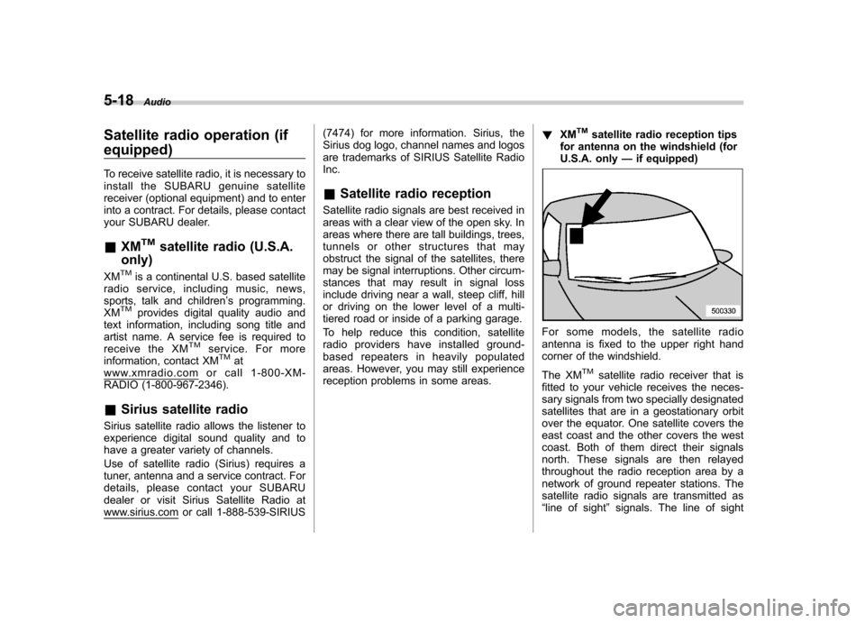
For some models, the satellite radio
antenna is fixed to the upper right hand
corner of the windshield.
The XM
TMsatellite radio receiver that is
fitted to your vehicle receives the neces-
sary signals from two specially designated
satellites that are in a geostationary orbit
over the equator. One satellite covers the
east coast and the other covers the west
coast. Both of them direct their signals
north. These signals are then relayed
throughout the radio reception area by a
network of ground repeater stations. The
satellite radio signals are transmitted as“ line of sight ”signals. The line of sight
Page 260 of 446
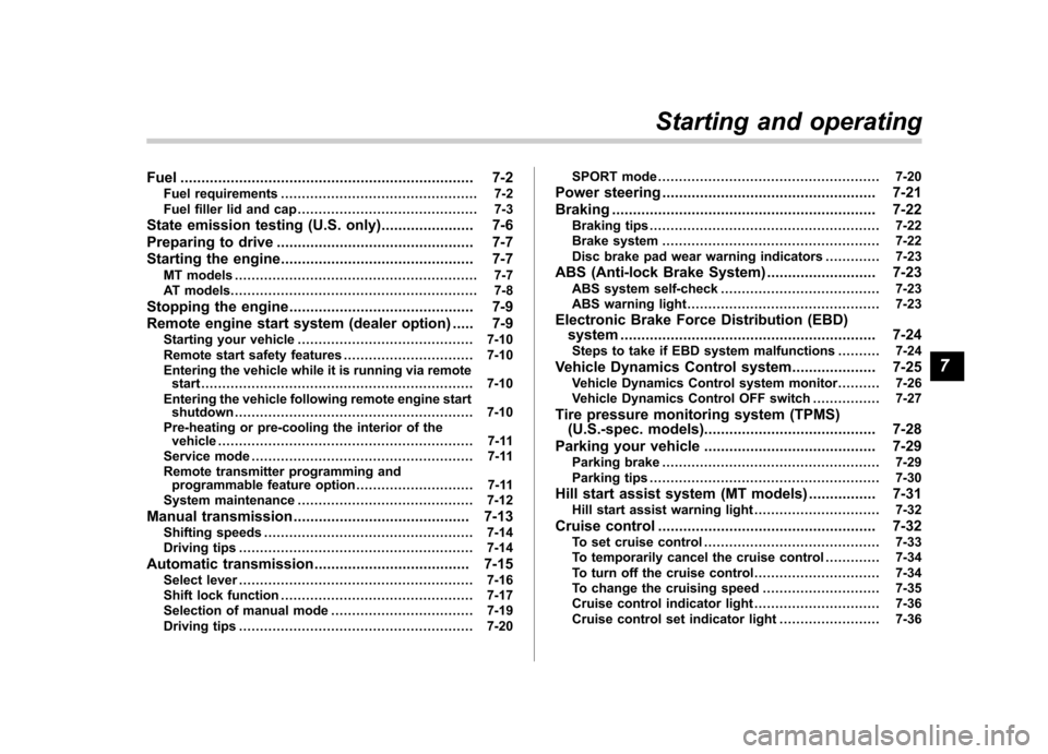
Fuel...................................................................... 7-2
Fuel requirements ............................................... 7-2
Fuel filler lid and cap ........................................... 7-3
State emission testing (U.S. only) ...................... 7-6
Preparing to drive ............................................... 7-7
Starting the engine .............................................. 7-7
MT models .......................................................... 7-7
AT models ........................................................... 7-8
Stopping the engine ............................................ 7-9
Remote engine start system (dealer option) ..... 7-9
Starting your vehicle .......................................... 7-10
Remote start safety features ............................... 7-10
Entering the vehicle while it is running via remote start ................................................................. 7-10
Entering the vehicle following remote engine start shutdown ......................................................... 7-10
Pre-heating or pre-cooling the interior of the vehicle ............................................................. 7-11
Service mode ..................................................... 7-11
Remote transmitter programming and programmable feature option ............................ 7-11
System maintenance .......................................... 7-12
Manual transmission .......................................... 7-13
Shifting speeds .................................................. 7-14
Driving tips ........................................................ 7-14
Automatic transmission ..................................... 7-15
Select lever ........................................................ 7-16
Shift lock function .............................................. 7-17
Selection of manual mode .................................. 7-19
Driving tips ........................................................ 7-20 SPORT mode
..................................................... 7-20
Power steering ................................................... 7-21
Braking ............................................................... 7-22
Braking tips ....................................................... 7-22
Brake system .................................................... 7-22
Disc brake pad wear warning indicators ............. 7-23
ABS (Anti-lock Brake System) .......................... 7-23
ABS system self-check ...................................... 7-23
ABS warning light .............................................. 7-23
Electronic Brake Force Distribution (EBD) system ............................................................. 7-24
Steps to take if EBD system malfunctions ..... ..... 7-24
Vehicle Dynamics Control system .................... 7-25
Vehicle Dynamics Control system monitor..... ..... 7-26
Vehicle Dynamics Control OFF switch ................ 7-27
Tire pressure monitoring system (TPMS) (U.S.-spec. models). ........................................ 7-28
Parking your vehicle ......................................... 7-29
Parking brake .................................................... 7-29
Parking tips ....................................................... 7-30
Hill start assist system (MT models) ................ 7-31
Hill start assist warning light .............................. 7-32
Cruise control .................................................... 7-32
To set cruise control .......................................... 7-33
To temporarily cancel the cruise control ............. 7-34
To turn off the cruise control .............................. 7-34
To change the cruising speed .. .......................... 7-35
Cruise control indicator light .............................. 7-36
Cruise control set indicator light ........................ 7-36
Starting and operating
7
Page 274 of 446
speed due to slow traffic, turning corners,
or driving up steep hills, downshift to a
lower gear before the engine starts to
labor.
On steep downgrades, downshift the
transmission to 4th, 3rd or 2nd gear as
necessary; this helps to maintain a safe
speed and to extend brake pad life.
In this way, the engine provides a braking
effect. Remember, if you“ride ”(over use)
the brakes while descending a hill, they
may overheat and not work properly.
The engine may, on rare occasions, knock
when the vehicle rapidly accelerates or
rapidly pulls away from a standstill. This
phenomenon is not an indication of a
problem in your vehicle. Automatic transmission
The automatic transmission is electroni-
cally controlled and provides 4 forward
speeds and 1 reverse speed. Also, it has a
manual mode and a SPORT mode.
WARNING
Do not shift from the “P ” or “N ”
position into the “D ” or “R ” position
while depressing the accelerator
pedal. This may cause the vehicle
to jump forward or backward.
CAUTION
. Shift into the “P ” or “R ” position
only after the vehicle is comple-
tely stopped. Shifting while the
vehicle is moving may cause
damage to the transmission.
. Do not race the engine for more
than 5 seconds in any position
except the “N ” or “P ” position
when the brake is set or when
chocks are used in the wheels.
This may cause the automatic
transmission fluid to overheat.
. Avoid shifting from one of the
forward driving positions into the “
R ” position or vice versa until
the vehicle has completely
stopped. Such shifting may
cause damage to the transmis-sion.
. When parking the vehicle, first
securely apply the parking brake
and then place the select lever inthe “P ” position. Avoid parking
for a long time with the select
lever in any other position as
doing so could result in a dead
battery.
NOTE . When the engine coolant tempera-
ture is still low, the automatic transmis-
sion will upshift to higher engine
speeds than when the coolant tempera-
ture is sufficiently high in order to
shorten the warm-up time and improve
driveability. The gearshift timing will
automatically shift to the normal timing
after the engine has warmed up.. Immediately after ATF (automatic
transmission fluid) is replaced, you
may feel that the automatic transmis-
sion operation is somewhat unusual.
This results from invalidation of data
which the on-board computer has
collected and stored in memory to Starting and operating
7-15
– CONTINUED –
Page 275 of 446
7-16Starting and operating
allow the transmission to shift at the
most appropriate times for the current
condition of your vehicle. Optimized
shifting will be restored as the vehicle
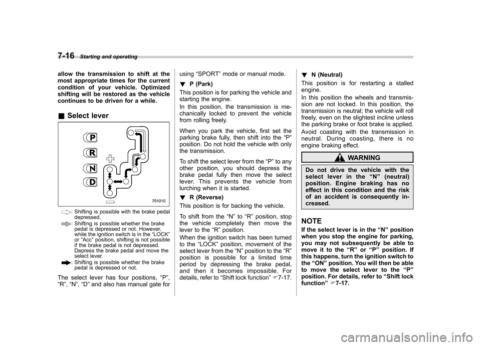
continues to be driven for a while. &Select lever
: Shifting is possible with the brake pedal
depressed.
: Shifting is possible whether the brakepedal is depressed or not. However,
while the ignition switch is in the “LOCK ”
or “Acc ”position, shifting is not possible
if the brake pedal is not depressed.
Depress the brake pedal and move the
select lever.
: Shifting is possible whether the brake pedal is depressed or not.
The select lever has four positions, “P ”,
“ R ”, “N ”, “D ”and also has manual gate for using
“SPORT ”mode or manual mode.
! P (Park)
This position is for parking the vehicle and
starting the engine.
In this position, the transmission is me-
chanically locked to prevent the vehicle
from rolling freely.
When you park the vehicle, first set the
parking brake fully, then shift into the “P ”
position. Do not hold the vehicle with only
the transmission.
To shift the select lever from the “P ”to any
other position, you should depress the
brake pedal fully then move the select
lever. This prevents the vehicle from
lurching when it is started. ! R (Reverse)
This position is for backing the vehicle.
To shift from the “N ”to “R ” position, stop
the vehicle completely then move the
lever to the “R ”position.
When the ignition switch has been turned
to the “LOCK ”position, movement of the
select lever from the “N ”position to the “R ”
position is possible for a limited time
period by depressing the brake pedal,
and then it becomes impossible. For
details, refer to “Shift lock function ”F 7-17. !
N (Neutral)
This position is for restarting a stalled engine.
In this position the wheels and transmis-
sion are not locked. In this position, the
transmission is neutral; the vehicle will roll
freely, even on the slightest incline unless
the parking brake or foot brake is applied.
Avoid coasting with the transmission in
neutral. During coasting, there is no
engine braking effect.
WARNING
Do not drive the vehicle with the
select lever in the “N ” (neutral)
position. Engine braking has no
effect in this condition and the risk
of an accident is consequently in-creased.
NOTE
If the select lever is in the “N ” position
when you stop the engine for parking,
you may not subsequently be able to
move it to the “R ” or “P ” position. If
this happens, turn the ignition switch to the “ON ”position. You will then be able
to move the select lever to the “P ”
position. For details, refer to “Shift lock
function ”F 7-17.
Page 276 of 446

!D (Drive)
This position is for normal driving.
The transmission automatically shifts into
a suitable gear from 1st to 4th according to
the vehicle speed and the acceleration
you require.
When more acceleration is required in this
position, depress the accelerator pedal
fully to the floor and hold that position. The
transmission will automatically downshift
to 3rd, 2nd or 1st gear. When you release
the pedal, the transmission will return to
the original gear position.
To use the “SPORT ”mode, move the lever
from this position into the manual gate. To
use the manual mode, move the lever
from this position into the manual gate
then move it toward the “+ ” and “� ” ends.
! While climbing a grade
When driving up a hill, undesired upshift to
4th gear is prevented from taking place
when the accelerator is released. This
minimizes the chance of subsequent
downshifting to a lower gear when accel-
erating again. This prevents repeated
upshifting and downshifting resulting in a
smoother operation of the vehicle.
NOTE
The transmission may downshift to 2nd
or 1st gear, depending on the way the accelerator pedal is pressed to accel-
erate the vehicle again. !
While going down a hill
When you are descending a hill or any
other slope while braking with the“ SPORT ”mode selected, the transmission
may downshift to 3rd or 2nd gear depend-
ing on how hard you depress the brake
pedal, causing engine braking to work.
Reacceleration for a short time will cause
the transmission to upshift normally.
NOTE . A 4th-to-3rd automatic downshift
will not occur at speeds above 50
mph (80 km/h) and a 3rd-to-2nd auto-
matic downshift will not occur at
speeds above 24 mph (38 km/h).. Automatic downshifts to 3rd or 2nd
may occur even when driving on a level
road depending on conditions, such as
how hard you depress the brake pedal. & Shift lock function
The shift lock function helps prevent the
improper operation of the select lever. . The select lever cannot be operated
unless the ignition switch is turned to the “ ON ”position and the brake pedal is
depressed. . The select lever cannot be moved from the
“P ” position to any other position
before the brake pedal is depressed.
Depress the brake pedal first, and then
operate the select lever. . Only the “P ”position allows you to turn
the key from the “Acc ”position to the
“ LOCK ”position and remove the key from
the ignition key cylinder.. If the ignition switch is turned to the
“ LOCK ”position while the select lever is in
the “N ”position, the select lever may not
be moved to the “P ”position after a period
of time. Therefore, move the select lever
to the “P ” position with the brake pedal
depressed soon after the ignition switch is
turned to the “LOCK ”position.
! Shift lock release
If the select lever cannot be operated, turn
the ignition switch back to the “ON ”
position then move the select lever to the“ P ” position with the brake pedal de-
pressed.
If the select lever does not move after
performing the above procedure, perform
the following steps. . When the select lever cannot be
shifted from “P ” to “N ”:
Refer to “Shift lock release using the shift
lock release button ”F 7-18.
Starting and operating
7-17
– CONTINUED –
Page 279 of 446

7-20Starting and operating
end of the manual gate.
Shift to the next-lower gear by briefly
pulling the select lever toward the “� ”
end of the manual gate. NOTE
Please read the following points care-
fully and bear them in mind when using
the manual mode. . If you attempt to shift down when
the engine speed is too high, i.e., when
a downshift would push the tachometer
needle beyond the red zone, beeps will
be emitted to warn you that the down-
shift is not possible.. If you attempt to shift up when the
vehicle speed is too low, the transmis-
sion will not respond.. You can perform a skip-shift (for
example, from 4th to 2nd) by operating
the select lever twice in rapid succes-sion.. The transmission automatically se-
lects 1st gear when the vehicle stopsmoving.. If the temperature of the automatic
transmission fluid becomes too high,the “AT OIL TEMP ”warning light will
illuminate and upshifts to 4th gear will
not be possible. Immediately stop the
vehicle in a safe place and let the
engine idle until the warning light turns off. &
Driving tips
. On a road surface where there is a risk
of wheelspin (for example, a snow- or
gravel-covered road), you can pull away
from a standstill (safely and easily) by first
selecting the 2nd gear of the manualmode. . Always apply the foot or parking brake
when the vehicle is stopped in the “D ”or
“ R ”position.
. Always set the parking brake when
parking your vehicle. Do not hold the
vehicle with only the transmission. . Do not keep the vehicle in a stationary
position on an uphill grade by using the “ D ”position. Use the brake instead.
. The engine may, on rare occasions,
knock when the vehicle rapidly acceler-
ates or rapidly pulls away from a standstill.
This phenomenon does not indicate aproblem. &
SPORT mode
SPORT mode is used when power is
needed for rapid acceleration or for uphill
driving. To select this mode, move the
select lever from the “D ” position to the
manual gate.