SUBARU FORESTER 2012 SH / 3.G Owners Manual
Manufacturer: SUBARU, Model Year: 2012, Model line: FORESTER, Model: SUBARU FORESTER 2012 SH / 3.GPages: 438, PDF Size: 15.31 MB
Page 371 of 438
11-32Maintenance and service
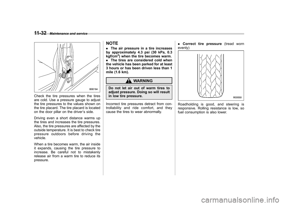
Check the tire pressures when the tires
are cold. Use a pressure gauge to adjust
the tire pressures to the values shown on
the tire placard. The tire placard is located
on the door pillar on the driver ’s side.
Driving even a short distance warms up
the tires and increases the tire pressures.
Also, the tire pressures are affected by the
outside temperature. It is best to check tire
pressure outdoors before driving thevehicle.
When a tire becomes warm, the air inside
it expands, causing the tire pressure to
increase. Be careful not to mistakenly
release air from a warm tire to reduce itspressure. NOTE .
The air pressure in a tire increases
by approximately 4.3 psi (30 kPa, 0.3 kgf/cm
2) when the tire becomes warm.
. The tires are considered cold when
the vehicle has been parked for at least
3 hours or has been driven less than 1
mile (1.6 km).
WARNING
Do not let air out of warm tires to
adjust pressure. Doing so will result
in low tire pressure.
Incorrect tire pressures detract from con-
trollability and ride comfort, and they
cause the tires to wear abnormally. .
Correct tire pressure (tread worn
evenly)
Roadholding is good, and steering is
responsive. Rolling resistance is low, so
fuel consumption is also lower.
Page 372 of 438
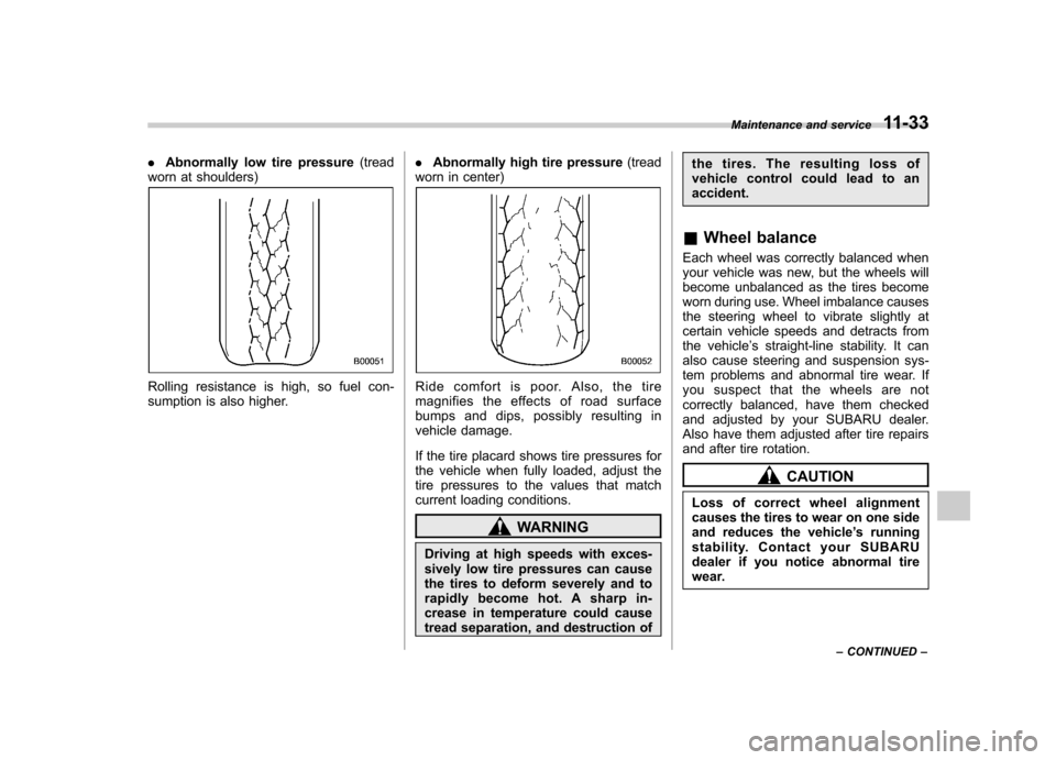
.Abnormally low tire pressure (tread
worn at shoulders)
Rolling resistance is high, so fuel con-
sumption is also higher. .
Abnormally high tire pressure (tread
worn in center)Ride comfort is poor. Also, the tire
magnifies the effects of road surface
bumps and dips, possibly resulting in
vehicle damage.
If the tire placard shows tire pressures for
the vehicle when fully loaded, adjust the
tire pressures to the values that match
current loading conditions.
WARNING
Driving at high speeds with exces-
sively low tire pressures can cause
the tires to deform severely and to
rapidly become hot. A sharp in-
crease in temperature could cause
tread separation, and destruction of the tires. The resulting loss of
vehicle control could lead to anaccident.
& Wheel balance
Each wheel was correctly balanced when
your vehicle was new, but the wheels will
become unbalanced as the tires become
worn during use. Wheel imbalance causes
the steering wheel to vibrate slightly at
certain vehicle speeds and detracts from
the vehicle ’s straight-line stability. It can
also cause steering and suspension sys-
tem problems and abnormal tire wear. If
you suspect that the wheels are not
correctly balanced, have them checked
and adjusted by your SUBARU dealer.
Also have them adjusted after tire repairs
and after tire rotation.
CAUTION
Loss of correct wheel alignment
causes the tires to wear on one side
and reduces the vehicle ’s running
stability. Contact your SUBARU
dealer if you notice abnormal tire
wear. Maintenance and service
11-33
– CONTINUED –
Page 373 of 438
11-34Maintenance and service
NOTE
The suspension system is designed to
hold each wheel at a certain alignment
(relative to the other wheels and to the
road) for optimum straight-line stability
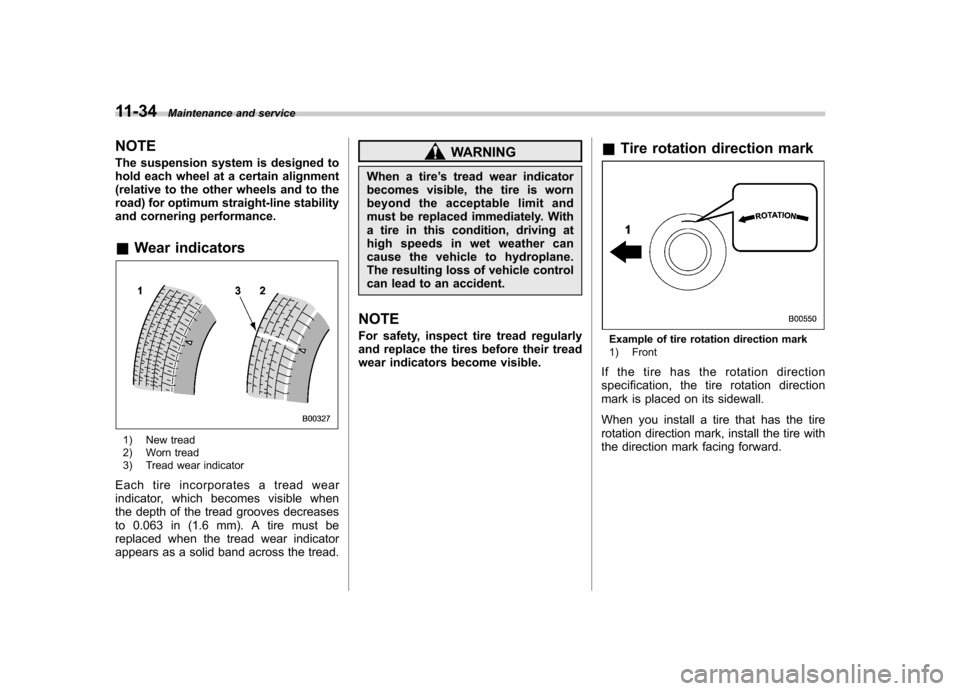
and cornering performance. &Wear indicators
1) New tread
2) Worn tread
3) Tread wear indicator
Each tire incorporates a tread wear
indicator, which becomes visible when
the depth of the tread grooves decreases
to 0.063 in (1.6 mm). A tire must be
replaced when the tread wear indicator
appears as a solid band across the tread.
WARNING
When a tire ’s tread wear indicator
becomes visible, the tire is worn
beyond the acceptable limit and
must be replaced immediately. With
a tire in this condition, driving at
high speeds in wet weather can
cause the vehicle to hydroplane.
The resulting loss of vehicle control
can lead to an accident.
NOTE
For safety, inspect tire tread regularly
and replace the tires before their tread
wear indicators become visible. &
Tire rotation direction mark
Example of tire rotation direction mark
1) Front
If the tire has the rotation direction
specification, the tire rotation direction
mark is placed on its sidewall.
When you install a tire that has the tire
rotation direction mark, install the tire with
the direction mark facing forward.
Page 374 of 438
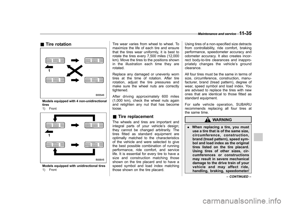
&Tire rotation
Models equipped with 4 non-unidirectional tires
1) Front
Models equipped with unidirectional tires
1) Front Tire wear varies from wheel to wheel. To
maximize the life of each tire and ensure
that the tires wear uniformly, it is best to
rotate the tires every 7,500 miles (12,000
km). Move the tires to the positions shown
in the illustration each time they arerotated.
Replace any damaged or unevenly worn
tires at the time of rotation. After tire
rotation, adjust the tire pressures and
make sure the wheel nuts are correctlytightened.
After driving approximately 600 miles
(1,000 km), check the wheel nuts again
and retighten any nut that has becomeloose. &
Tire replacement
The wheels and tires are important and
integral parts of your vehicle ’s design;
they cannot be changed arbitrarily. The
tires fitted as standard equipment are
optimally matched to the characteristics
of the vehicle and were selected to give
the best possible combination of running
performance, ride comfort, and service
life. It is essential for every tire to have a
size and construction matching those
shown on the tire placard and to have a
speed symbol and load index matching
those shown on the tire placard. Using tires of a non-specified size detracts
from controllability, ride comfort, braking
performance, speedometer accuracy and
odometer accuracy. It also creates incor-
rect body-to-tire clearances and inappro-
priately changes the vehicle
’s ground
clearance.
All four tires must be the same in terms of
size, circumference, construction, manu-
facturer, brand (tread pattern), degree of
wear, speed symbol and load index. You
are advised to replace the tires with new
ones that are identical to those fitted as
standard equipment.
For safe vehicle operation, SUBARU
recommends replacing all four tires at
the same time.
WARNING
. When replacing a tire, you must
use a tire that is of the same size,
circumference, construction,
brand (tread pattern), speed sym-
bol and load index as the original
tires listed on the tire placard.
Using tires of other sizes, cir-
cumferences or constructions
may result in severe mechanical
damage to the drive train of your
vehicle and may affect ride,
handling, braking, speedometer/ Maintenance and service
11-35
– CONTINUED –
Page 375 of 438
11-36Maintenance and service
odometer calibration, and clear-
ance between the body and tires.
It also may be dangerous and
lead to loss of vehicle control.
. You must install four tires that are
of the same size, circumference,
construction, manufacturer,
brand (tread pattern), degree of
wear, speed symbol and load
index. Mixing tires of different
types, sizes or degrees of wear
can result in damage to the
vehicle ’s power train. Use of
different types or sizes of tires
can also dangerously reduce
controllability and braking per-
formance and can lead to anaccident.
. Use only radial tires. Do not use
radial tires together with belted
bias tires and/or bias-ply tires.
Doing so can dangerously re-
duce controllability, resulting in
an accident.
& Wheel replacement
When replacing wheels due to damage,
for example, make sure the replacement
wheels match the specifications of the
wheels that are fitted as standard equip- ment. Replacement wheels are available
from SUBARU dealers.
WARNING
Use only those wheels that are
specified for your vehicle. Wheels
not meeting specifications could
interfere with brake caliper opera-
tion and may cause the tires to rub
against the wheel well housing dur-
ing turns. The resulting loss of
vehicle control could lead to anaccident.
NOTE
When any of the wheels are removed
and replaced for tire rotation or to
change a flat tire, always check the
tightness of the wheel nuts after driv-
ing approximately 600 miles (1,000 km).
If any nut is loose, tighten it to the
specified torque. &
Wheel covers (if equipped)
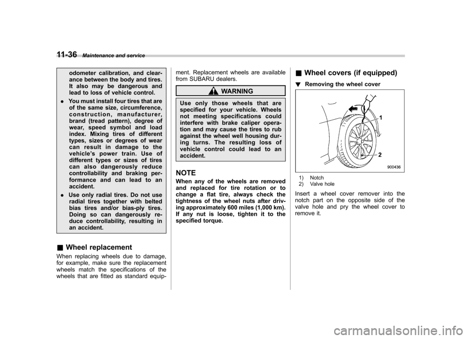
! Removing the wheel cover
1) Notch
2) Valve hole
Insert a wheel cover remover into the
notch part on the opposite side of the
valve hole and pry the wheel cover to
remove it.
Page 376 of 438
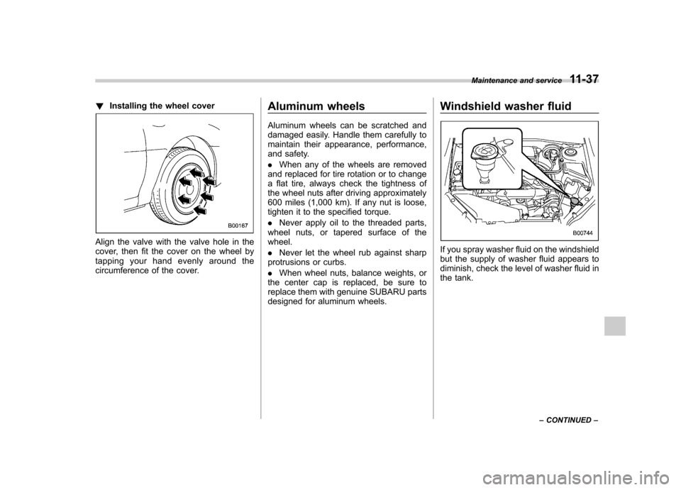
!Installing the wheel cover
Align the valve with the valve hole in the
cover, then fit the cover on the wheel by
tapping your hand evenly around the
circumference of the cover. Aluminum wheels
Aluminum wheels can be scratched and
damaged easily. Handle them carefully to
maintain their appearance, performance,
and safety. .
When any of the wheels are removed
and replaced for tire rotation or to change
a flat tire, always check the tightness of
the wheel nuts after driving approximately
600 miles (1,000 km). If any nut is loose,
tighten it to the specified torque. . Never apply oil to the threaded parts,
wheel nuts, or tapered surface of the wheel. . Never let the wheel rub against sharp
protrusions or curbs.. When wheel nuts, balance weights, or
the center cap is replaced, be sure to
replace them with genuine SUBARU parts
designed for aluminum wheels. Windshield washer fluidIf you spray washer fluid on the windshield
but the supply of washer fluid appears to
diminish, check the level of washer fluid in
the tank.Maintenance and service
11-37
– CONTINUED –
Page 377 of 438
11-38Maintenance and service
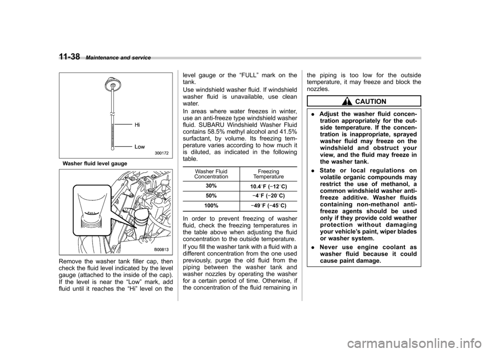
Washer fluid level gauge
Remove the washer tank filler cap, then
check the fluid level indicated by the level
gauge (attached to the inside of the cap).
If the level is near the “Low ”mark, add
fluid until it reaches the “Hi ”level on the level gauge or the
“FULL ”mark on the
tank.
Use windshield washer fluid. If windshield
washer fluid is unavailable, use clean
water.
In areas where water freezes in winter,
use an anti-freeze type windshield washer
fluid. SUBARU Windshield Washer Fluid
contains 58.5% methyl alcohol and 41.5%
surfactant, by volume. Its freezing tem-
perature varies according to how much it
is diluted, as indicated in the followingtable.
Washer Fluid
Concentration Freezing
Temperature
30% 10.48F( �12 8C)
50% �48F( �20 8C)
100% �49 8F( �45 8C)
In order to prevent freezing of washer
fluid, check the freezing temperatures in
the table above when adjusting the fluid
concentration to the outside temperature.
If you fill the washer tank with a fluid with a
different concentration from the one used
previously, purge the old fluid from the
piping between the washer tank and
washer nozzles by operating the washer
for a certain period of time. Otherwise, if
the concentration of the fluid remaining in the piping is too low for the outside
temperature, it may freeze and block thenozzles.
CAUTION
. Adjust the washer fluid concen-
tration appropriately for the out-
side temperature. If the concen-
tration is inappropriate, sprayed
washer fluid may freeze on the
windshield and obstruct your
view, and the fluid may freeze in
the washer tank.
. State or local regulations on
volatile organic compounds may
restrict the use of methanol, a
common windshield washer anti-
freeze additive. Washer fluids
containing non-methanol anti-
freeze agents should be used
only if they provide cold weather
protection without damaging
your vehicle ’s paint, wiper blades
or washer system.
. Never use engine coolant as
washer fluid because it could
cause paint damage.
Page 378 of 438
Replacement of wiper blades
Grease, wax, insects, or other material on
the windshield or the wiper blade results in
jerky wiper operation and streaking on the
glass. If you cannot remove the streaks
after operating the windshield washer or if
the wiper operation is jerky, clean the
outer surface of the windshield (or rear
window) and the wiper blades using a
sponge or soft cloth with a neutral
detergent or mild abrasive cleaner. After
cleaning, rinse the windshield and wiper
blades with clean water. The windshield is
clean if beads do not form when you rinse
the windshield with water.
CAUTION
. Do not clean the wiper blades
with gasoline or a solvent, such
as paint thinner or benzine. This
will cause deterioration of the
wiper blades.
. While removing the wiper blades
from the wiper arms, do not
return the wiper arms to the
original positions. Otherwise,
the windshield surface may bescratched.
. When returning the raised wiper
arms to the original positions, carefully return the wiper arms
on the windshield while support-
ing them with your hands. You
should not return the wiper arms
to the windshield only by the
return spring. Otherwise, the wi-
per arms may be deformed and/
or the windshield surface may bescratched.
If you cannot eliminate the streaking even
after following this method, replace the
wiper blades using the following proce-dures. &
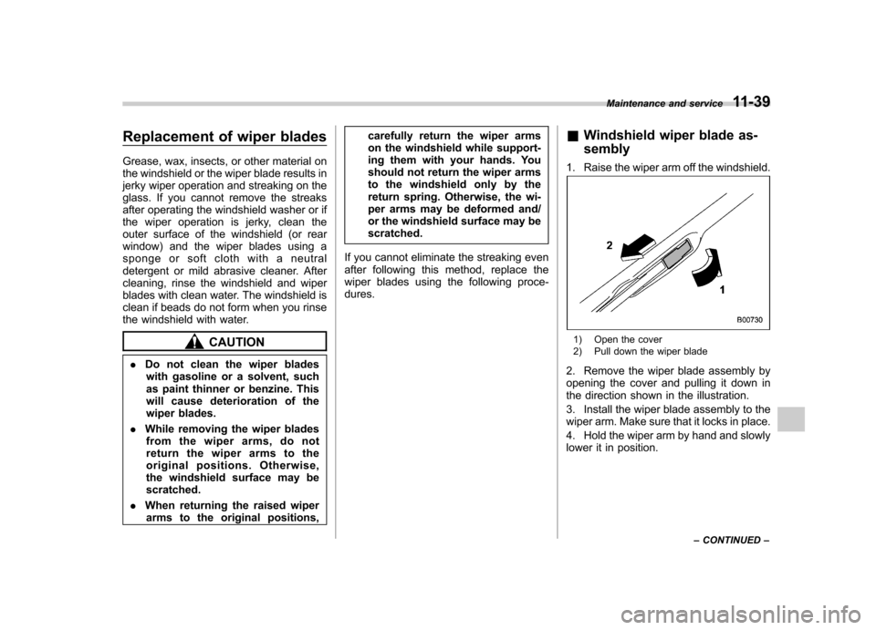
Windshield wiper blade as- sembly
1. Raise the wiper arm off the windshield.1) Open the cover
2) Pull down the wiper blade
2. Remove the wiper blade assembly by
opening the cover and pulling it down in
the direction shown in the illustration.
3. Install the wiper blade assembly to the
wiper arm. Make sure that it locks in place.
4. Hold the wiper arm by hand and slowly
lower it in position. Maintenance and service
11-39
– CONTINUED –
Page 379 of 438
11-40Maintenance and service
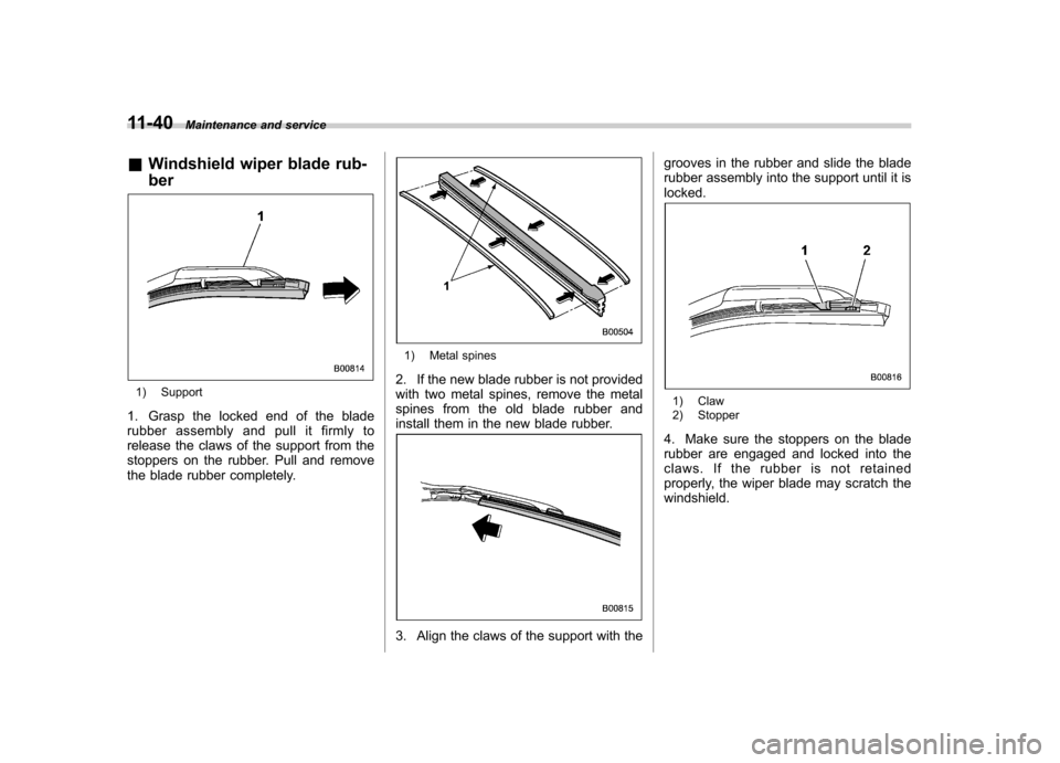
& Windshield wiper blade rub- ber
1) Support
1. Grasp the locked end of the blade
rubber assembly and pull it firmly to
release the claws of the support from the
stoppers on the rubber. Pull and remove
the blade rubber completely.
1) Metal spines
2. If the new blade rubber is not provided
with two metal spines, remove the metal
spines from the old blade rubber and
install them in the new blade rubber.
3. Align the claws of the support with the grooves in the rubber and slide the blade
rubber assembly into the support until it islocked.
1) Claw
2) Stopper
4. Make sure the stoppers on the blade
rubber are engaged and locked into the
claws. If the rubber is not retained
properly, the wiper blade may scratch thewindshield.
Page 380 of 438
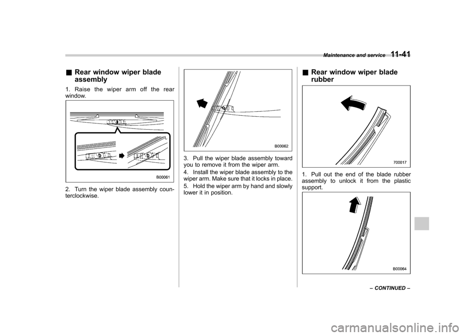
&Rear window wiper blade assembly
1. Raise the wiper arm off the rear
window.
2. Turn the wiper blade assembly coun- terclockwise.
3. Pull the wiper blade assembly toward
you to remove it from the wiper arm.
4. Install the wiper blade assembly to the
wiper arm. Make sure that it locks in place.
5. Hold the wiper arm by hand and slowly
lower it in position. &
Rear window wiper blade rubber
1. Pull out the end of the blade rubber
assembly to unlock it from the plasticsupport.
Maintenance and service 11-41
– CONTINUED –