tire size SUBARU FORESTER 2017 SJ / 4.G User Guide
[x] Cancel search | Manufacturer: SUBARU, Model Year: 2017, Model line: FORESTER, Model: SUBARU FORESTER 2017 SJ / 4.GPages: 634, PDF Size: 11.77 MB
Page 499 of 634
Driving tips/Trailer towing
the rear axle of the towing vehicle.
This may cause the rear wheels to
skid, especially during braking or
when vehicle speed is reduced dur-
ing cornering, resulting in over-
steer, spin out and/or jackknifing.
&Trailer hitches
WARNING
Never drill the frame or under-body
of your vehicle to install a commer-
cial trailer hitch. If you do, danger-
ous exhaust gas, water or mud may
enter the passenger compartment
through the drilled hole. Exhaust
gas contains carbon monoxide, a
colorless and odorless gas which is
dangerous, or even lethal, if inhaled.
Also, drilling the frame or under-
body of your vehicle could cause
deterioration of strength of your
vehicle and cause corrosion around
the drilled hole.
CAUTION
. Do not modify the vehicle ex-
haust system, brake system, or
other systems when installing a hitch or other trailer towing
equipment.
. Do not use axle-mounted hitches
as they can cause damage to the
axle housing, wheel bearings,
wheels or tires.
Do not use a trailer hitch other than a
genuine SUBARU trailer hitch. A genuine
SUBARU hitch is available from your
SUBARU dealer.
& Connecting a trailer
! Trailer brakes
WARNING
.Adequate size trailer brakes are
required when the trailer and its
cargo exceed 1,000 lbs (453 kg)
total weight.
. Do not directly connect your
trailer ’s hydraulic brake system
to the hydraulic brake system in
your vehicle. Direct connection
would cause the vehicle ’s brake
performance to deteriorate and
could lead to an accident.
If your trailer ’s total weight (trailer weight
plus its cargo weight) exceeds 1,000 lbs (453 kg), the trailer is required to be
equipped with its own brake system.
Electric brakes or surge brakes are
recommended, and must be installed
properly. Check that your trailer
’s brakes
conform with Federal, state/province and/
or other applicable regulations. Your
SUBARU ’s brake system is not designed
to be tapped into the trailer ’s hydraulic
brake system. Please ask your SUBARU
dealer and professional trailer supplier for
more information about the trailer ’s brake
system.
! Trailer safety chains
WARNING
Always use safety chains between
your vehicle and the trailer. Towing
trailer without safety chains could
create a traffic safety hazard if the
trailer separates from the hitch due
to coupling damage or hitch ball
damage.
In case the trailer hitch connector or hitch
ball should break or become discon-
nected, the trailer could get loose and
create a traffic safety hazard.
For safety, always connect the towing
vehicle and trailer with trailer safety
chains. Two chains should be used in
8-22
Page 500 of 634
total, one to the right side and the other to
the left side trailer tongue. Pass the chains
crossing each other under the trailer
tongue to prevent the trailer from dropping
onto the ground in case the trailer tongue
should disconnect from the hitch ball.
Allow sufficient slack in the chains taking
tight turn situations into account; however,
be careful not to let them drag on the
ground.
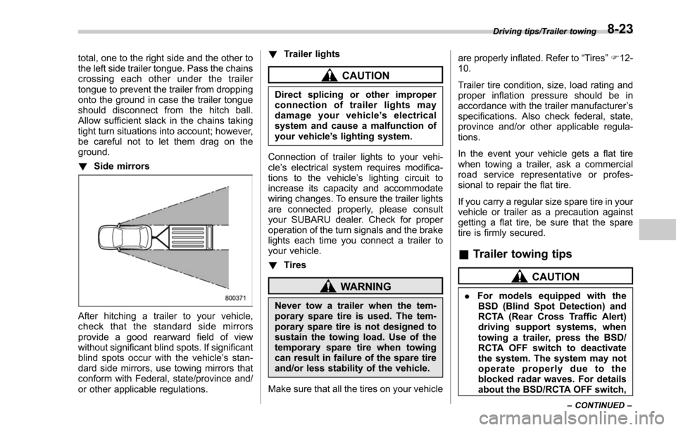
!Side mirrors
After hitching a trailer to your vehicle,
check that the standard side mirrors
provide a good rearward field of view
without significant blind spots. If significant
blind spots occur with the vehicle’ s stan-
dard side mirrors, use towing mirrors that
conform with Federal, state/province and/
or other applicable regulations. !
Trailer lights
CAUTION
Direct splicing or other improper
connection of trailer lights may
damage your vehicle’ s electrical
system and cause a malfunction of
your vehicle ’s lighting system.
Connection of trailer lights to your vehi-
cle ’s electrical system requires modifica-
tions to the vehicle ’s lighting circuit to
increase its capacity and accommodate
wiring changes. To ensure the trailer lights
are connected properly, please consult
your SUBARU dealer. Check for proper
operation of the turn signals and the brake
lights each time you connect a trailer to
your vehicle.
! Tires
WARNING
Never tow a trailer when the tem-
porary spare tire is used. The tem-
porary spare tire is not designed to
sustain the towing load. Use of the
temporary spare tire when towing
can result in failure of the spare tire
and/or less stability of the vehicle.
Make sure that all the tires on your vehicle are properly inflated. Refer to
“Tires”F 12-
10.
Trailer tire condition, size, load rating and
proper inflation pressure should be in
accordance with the trailer manufacturer ’s
specifications. Also check federal, state,
province and/or other applicable regula-
tions.
In the event your vehicle gets a flat tire
when towing a trailer, ask a commercial
road service representative or profes-
sional to repair the flat tire.
If you carry a regular size spare tire in your
vehicle or trailer as a precaution against
getting a flat tire, be sure that the spare
tire is firmly secured.
& Trailer towing tips
CAUTION
. For models equipped with the
BSD (Blind Spot Detection) and
RCTA (Rear Cross Traffic Alert)
driving support systems, when
towing a trailer, press the BSD/
RCTA OFF switch to deactivate
the system. The system may not
operate properly due to the
blocked radar waves. For details
about the BSD/RCTA OFF switch,
Driving tips/Trailer towing
–CONTINUED –8-23
Page 506 of 634
CAUTION
Never use any temporary spare tire
other than the original. Using other
sizes may result in severe mechan-
ical damage to the drive train of your
vehicle.
The temporary spare tire is smaller and
lighter than a conventional tire and is
designed for emergency use only. Re-
move the temporary spare tire and re-
install the conventional tire as soon as
possible because the spare tire is de-
signed only for temporary use.
Check the inflation pressure of the tem-
porary spare tire periodically to keep the
tire ready for use. For the correct tire
pressure, refer to “Tires”F 12-10.
When using the temporary spare tire, note
the following.
. Do not exceed 50 mph (80 km/h).
. Do not put a tire chain on the temporary
spare tire. Because of the smaller tire size,
a tire chain will not fit properly.
. Do not use two or more temporary
spare tires at the same time.
. Do not drive over obstacles. This tire
has a smaller diameter, so road clearance
is reduced.
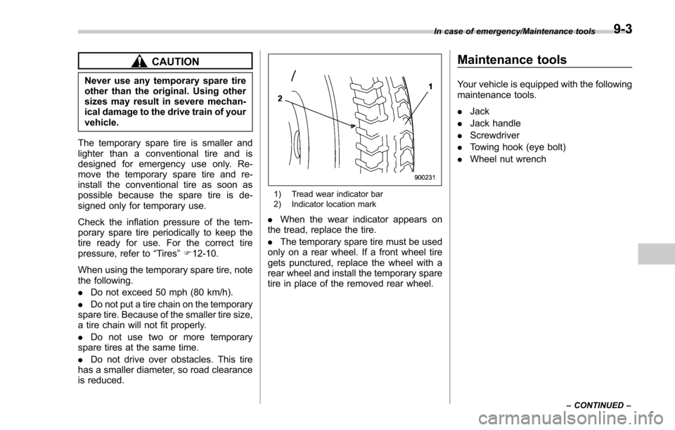
1) Tread wear indicator bar
2) Indicator location mark
. When the wear indicator appears on
the tread, replace the tire.
. The temporary spare tire must be used
only on a rear wheel. If a front wheel tire
gets punctured, replace the wheel with a
rear wheel and install the temporary spare
tire in place of the removed rear wheel.
Maintenance tools
Your vehicle is equipped with the following
maintenance tools.
. Jack
. Jack handle
. Screwdriver
. Towing hook (eye bolt)
. Wheel nut wrench
In case of emergency/Maintenance tools
–CONTINUED –9-3
Page 555 of 634
Maintenance and service/Tires and wheels
temperature outside. By way of example,
the following table shows the required tire
pressures that correspond to various out-
side temperatures when the temperature
in the garage is 608F (15.6 8C).
Example:
Tire size: P205/55R16 89V and
P205/50R17 88V
Standard tire pressures:
Front: 33 psi (230 kPa, 2.3 kgf/cm
2)
Rear: 32 psi (220 kPa, 2.2 kgf/cm2)
Garage temperature: 60 8F (15.6 8C)
Outside
temperature Adjusted pressure
[psi (kPa, kgf/cm2)]
Front Rear
30 8F( −18C) 36 (250, 2.5) 35 (240, 2.4)
10 8F( −12 8C) 38
(260, 2.6) 37
(255, 2.55)
−10 8F( −23 8C) 40
(275, 2.75) 39 (270, 2.7)
If the low tire pressure warning light
illuminates when you drive the vehicle in
cold outside air after adjusting the tire
pressures in a warm garage, re-adjust the
tire pressures using the method described
above. Then, increase the vehicle speed
to at least 25 mph (40 km/h) and check to
see that the low tire pressure warning light
turns off a few minutes later. If the low tire pressure warning light does not turn off,
the tire pressure monitoring system may
not be functioning normally. In this event,
go to a SUBARU dealer to have the
system inspected as soon as possible.
While the vehicle is driven, friction be-
tween tires and the road surface causes
the tires to warm up. After illumination of
the low tire pressure warning light, any
increase in the tire pressures caused by
an increase in the outside air temperature
or by an increase in the temperature in the
tires can cause the low tire pressure
warning light to turn off.
System resetting is necessary when the
wheels are changed (for example, a
switch to snow tires) and new TPMS
valves are installed on the newly fitted
wheels. Have this work performed by a
SUBARU dealer following wheel replace-
ment.
It may not be possible to install TPMS
valves on certain wheels that are on the
market. Therefore, if you change the
wheels (for example, a switch to snow
tires), use wheels that have the same part
number as the standard-equipment
wheels. Without four operational TPMS
valve/sensors on the wheels, the TPMS
will not fully function and the warning light
on the combination meter will illuminatesteadily after blinking for approximately
one minute.
When a tire is replaced, adjustments are
necessary to ensure continued normal
operation of the tire pressure monitoring
system. As with wheel replacement, there-
fore, you should have the work performed
by a SUBARU dealer.
WARNING
If the low tire pressure warning light
does not illuminate briefly after the
ignition switch is turned ON or the
light illuminates steadily after blink-
ing for approximately one minute,
you should have your Tire Pressure
Monitoring System checked at a
SUBARU dealer as soon as possi-
ble.
If this light illuminates while driving,
never brake suddenly. Instead, per-
form the following procedure. Other-
wise an accident involving serious
vehicle damage and serious perso-
nal injury could occur.
1) Keep driving straight ahead while
gradually reducing speed.
2) Slowly pull off the road to a safe place.
If this light still illuminates while
11-24
Page 560 of 634
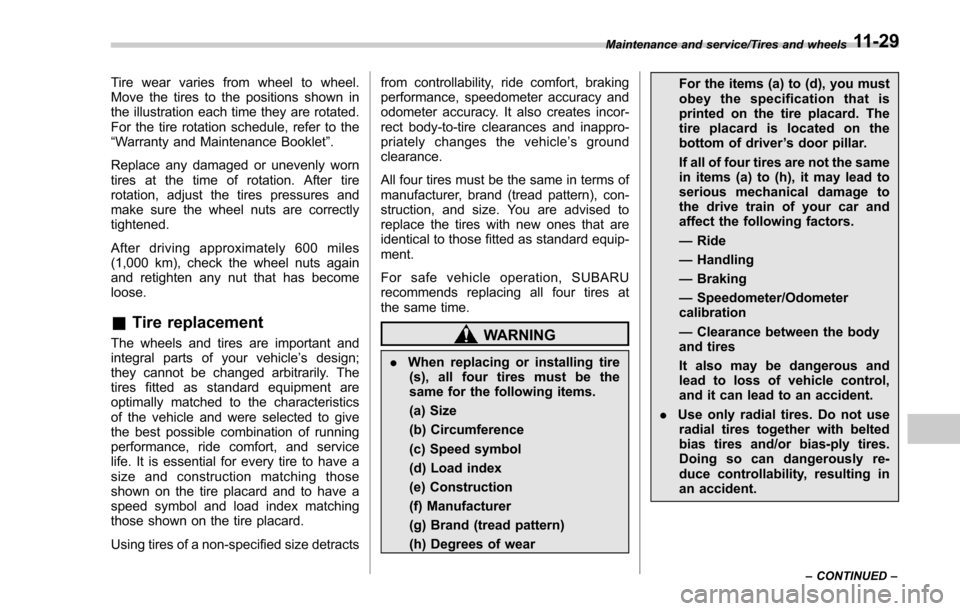
Tire wear varies from wheel to wheel.
Move the tires to the positions shown in
the illustration each time they are rotated.
For the tire rotation schedule, refer to the
“Warranty and Maintenance Booklet”.
Replace any damaged or unevenly worn
tires at the time of rotation. After tire
rotation, adjust the tires pressures and
make sure the wheel nuts are correctly
tightened.
After driving approximately 600 miles
(1,000 km), check the wheel nuts again
and retighten any nut that has become
loose.
& Tire replacement
The wheels and tires are important and
integral parts of your vehicle’ s design;
they cannot be changed arbitrarily. The
tires fitted as standard equipment are
optimally matched to the characteristics
of the vehicle and were selected to give
the best possible combination of running
performance, ride comfort, and service
life. It is essential for every tire to have a
size and construction matching those
shown on the tire placard and to have a
speed symbol and load index matching
those shown on the tire placard.
Using tires of a non-specified size detracts from controllability, ride comfort, braking
performance, speedometer accuracy and
odometer accuracy. It also creates incor-
rect body-to-tire clearances and inappro-
priately changes the vehicle
’s ground
clearance.
All four tires must be the same in terms of
manufacturer, brand (tread pattern), con-
struction, and size. You are advised to
replace the tires with new ones that are
identical to those fitted as standard equip-
ment.
For safe vehicle operation, SUBARU
recommends replacing all four tires at
the same time.WARNING
. When replacing or installing tire
(s), all four tires must be the
same for the following items.
(a) Size
(b) Circumference
(c) Speed symbol
(d) Load index
(e) Construction
(f) Manufacturer
(g) Brand (tread pattern)
(h) Degrees of wear For the items (a) to (d), you must
obey the specification that is
printed on the tire placard. The
tire placard is located on the
bottom of driver
’s door pillar.
If all of four tires are not the same
in items (a) to (h), it may lead to
serious mechanical damage to
the drive train of your car and
affect the following factors.
— Ride
— Handling
— Braking
— Speedometer/Odometer
calibration
— Clearance between the body
and tires
It also may be dangerous and
lead to loss of vehicle control,
and it can lead to an accident.
. Use only radial tires. Do not use
radial tires together with belted
bias tires and/or bias-ply tires.
Doing so can dangerously re-
duce controllability, resulting in
an accident.
Maintenance and service/Tires and wheels
–CONTINUED –11-29
Page 589 of 634
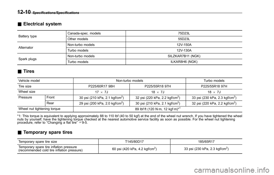
Specifications/Specifications
&Electrical system
Battery type Canada-spec. models 75D23L
Other models
55D23L
Alternator Non-turbo models
12V-150A
Turbo models 12V-130A
Spark plugs Non-turbo models
SILZKAR7B11 (NGK)
Turbo models ILKAR8H6 (NGK)
&
Tires
Vehicle model Non-turbo modelsTurbo models
Tire size P225/60R17 98HP225/55R18 97H P225/55R18 97H
Wheel size 1767J 1867J 1867J
Pressure Front 30 psi (210 kPa, 2.1 kgf/cm
2) 32 psi (220 kPa, 2.2 kgf/cm2) 33 psi (230 kPa, 2.3 kgf/cm2)
Rear 29 psi (200 kPa, 2.0 kgf/cm2) 30 psi (210 kPa, 2.1 kgf/cm2) 32 psi (220 kPa, 2.2 kgf/cm2)
Wheel nut tightening torque 89 lbf·ft (120 N·m, 12 kgf·m)*1
*1: This torque is equivalent to applying approximately 88 to 110 lbf (40 to 50 kgf) at the end of the wheel nut wrench. If you have tightened the wheel
nuts by yourself, have the tightening torque checked at the nearest automotive service facility as soon as possible. For the wheel nut tightening
procedure, refer to“Changing a flat tire ”F 9-5.
& Temporary spare tires
Temporary spare tire size T145/80D17185/65R17
Temporary spare tire inflation pressure
(recommended cold tire inflation pressure) 60 psi (420 kPa, 4.2 kgf/cm
2)
33 psi (230 kPa, 2.3 kgf/cm2)
12-10
Page 601 of 634

Consumer information and Reporting safety defects/For U.S.A.
For U.S.A.
The following information has been
compiled according to Code of
Federal Regulations“Title 49, Part
575 ”.
Tire information
& Tire labeling
Many markings (e.g. Tire size, Tire
Identification Number or TIN) are
placed on the sidewall of a tire by
tire manufacturers. These markings
can provide you with useful infor-
mation on the tire.
! Tire size
Your vehicle comes equipped with
P-Metric tire size. It is important to
understand the sizing system in
selecting the proper tire for your
vehicles. Here is a brief review of
the tire sizing system with a break-
down of its individual elements.
!P Metric
With the P-Metric system, Section
Width is measured in millimeters.
To convert millimeters into inches,
divide by 25.4. The Aspect Ratio
(Section Height divided by Section
Width) helps provide more dimen-
sional information about the tire
size.
Example:
(1) P = Certain tire type used on
light duty vehicles such as passen-
ger cars
(2) Section Width in millimeters
(3) Aspect Ratio (= section height
7 section width).
(4) R = Radial Construction
(5) Rim diameter in inches
! Load and Speed Rating De-
scriptions
The load and speed rating descrip-
tions will appear following the size
designation.
They provide two important facts
about the tire. First, the number
designation is its load index. Sec-
ond, the letter designation indicates
the tire’ s speed rating.
13-2
Page 602 of 634

Example:
(6) Load Index: A numerical code
which specifies the maximum load
a tire can carry at the speed
indicated by its speed symbol, at
maximum inflation pressure.
For example,“90 ”means 1,323 lbs
(600 kg), “89 ”means 1,278 lbs (580
kg).
WARNING
Load indices apply only to the
tire, not to the vehicle. Putting
a load rated tire on any vehicle
does not mean the vehicle can
be loaded up to the tire ’s rated
load.
(7) Speed Rating: An alphabetical
system describing a tire ’s capability
to travel at established and prede-
termined speeds.
For example, “V ” means 149 mph
(240 km/h)
WARNING
.Speed ratings apply only to the tire, not to the vehicle.
Putting a speed rated tire on
any vehicle does not mean
the vehicle can be operated
at the tire ’s rated speed.
.The speed rating is void if
the tires are worn out, da-
maged, repaired, retreaded,
or otherwise altered from
their original condition. If
tires are repaired, re-
treaded, or otherwise al-
tered, they may not be sui-
table for original equipment
tire designed loads and
speeds.
! Tire Identification Number (TIN)
Tire Identification Number (TIN) is
marked on the intended outboard
sidewall. The TIN is composed of
four groups. Here is a brief review
of the TIN with a breakdown of its
individual elements.
(1) Manufacturer ’s Identification
Mark
(2) Tire Size
(3) Tire Type Code
(4) Date of Manufacture
The first two figures identify the
week, starting with “01 ”to represent
the first full week of the calendar
year; the second two figures repre-
sent the year. For example, 0101
means the 1st week of 2001.
! Other markings
The following makings are also
placed on the sidewall.
!Maximum permissible infla-
tion pressure
The maximum cold inflation pres-
sure to which this tire may be
inflated. For example, “300 kPa
(44 PSI) MAX. PRESS ”
Consumer information and Reporting safety defects/Tire information
–CONTINUED –13-3
Page 603 of 634
Consumer information and Reporting safety defects/Tire information
!Maximum load rating
The load rating at the maximum
permissible weight load for this tire.
For example, “MAX. LOAD 580 kg
(1279 LBS) @ 300 kPa (44 PSI)
MAX. PRESS. ”
WARNING
Maximum load rating applies
only to the tire, not to the
vehicle. Putting a load rated
tire on any vehicle does not
mean the vehicle can be
loaded up to the tire ’s rated
load.
! Construction type
Applicable construction of this tire.
For example, “TUBELESS STEEL
BELTED RADIAL”
! Construction
The generic name of each cord
material used in the plies (both
sidewall and tread area) of this tire.
For example, “PLIES: TREAD 2 STEEL + 2 POLYESTER SIDE-
WALL 2 POLYESTER
”
!Uniform Tire Quality Grading
(UTQG)
For details, refer to “Uniform tire
quality grading standards ”F 13-15
.
& Recommended tire inflation
pressure
! Recommended cold tire infla-
tion pressure
For recommended cold tire inflation
pressure for your vehicle ’s tires,
refer to “Tires ”F 12-10
.
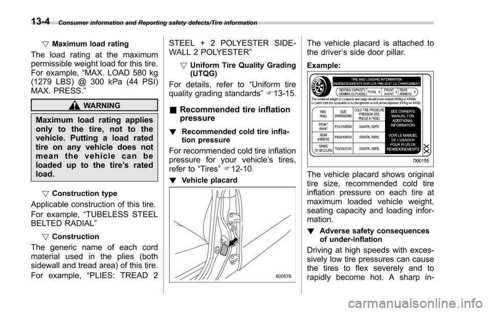
! Vehicle placard
The vehicle placard is attached to
the driver ’s side door pillar.
Example:
The vehicle placard shows original
tire size, recommended cold tire
inflation pressure on each tire at
maximum loaded vehicle weight,
seating capacity and loading infor-
mation.
! Adverse safety consequences
of under-inflation
Driving at high speeds with exces-
sively low tire pressures can cause
the tires to flex severely and to
rapidly become hot. A sharp in-
13-4
Page 606 of 634
.Passenger car tire
A tire intended for use on passen-
ger cars, multipurpose passenger
vehicles, and trucks, that have a
gross vehicle weight rating (GVWR)
of 10,000 lbs (4,535 kg) or less.
.Ply
A layer of rubber-coated parallel
cords.
.Ply separation
A parting of rubber compound
between adjacent plies.
.Pneumatic tire
A mechanical device made of rub-
ber, chemicals, fabric and steel or
other materials, that, when
mounted on an automotive wheel,
provides the traction and contains
the gas or fluid that sustains the
load.
.Production options weight
The combined weight of those
installed regular production options
weighing over 5.1 lbs (2.3 kg) in
excess of those standard items
which they replace, not previously
considered in curb weight or acces-sory weight, including heavy duty
brakes, ride levelers, roof rack,
heavy duty battery, and special
trim.
.Radial ply tire
A pneumatic tire in which the ply
cords that extend to the beads are
laid at substantially 90 degrees to
the centerline of the tread.
.Recommended inflation pres-
sure
The cold inflation pressure recom-
mended by a vehicle manufacturer.
.Reinforced tire
A tire designed to operate at higher
loads and at higher inflation pres-
sures than the corresponding stan-
dard tire.
.Rim
A metal support for a tire or a tire
and tube assembly upon which the
tire beads are seated.
.Rim diameter
Nominal diameter of the bead seat.
.Rim size designation
Rim diameter and width.
.Rim type designation
The industry of manufacturer ’s des-
ignation for a rim by style or code.
.Rim width
Nominal distance between rim
flanges.
.Section width
The linear distance between the
exteriors of the sidewalls of an
inflated tire, excluding elevations
due to labeling, decoration, or
protective bands.
.Sidewall
That portion of a tire between the
tread and bead.
.Sidewall separation
The parting of the rubber com-
pound from the cord material in
the sidewall.
.Test rim
The rim on which a tire is fitted for
testing, and it may be any rim listed
as appropriate for use with that tire.
.Tread
That portion of a tire that comes
into contact with the road.
Consumer information and Reporting safety defects/Tire information
–CONTINUED –13-7