turn signal SUBARU FORESTER 2017 SJ / 4.G Owners Manual
[x] Cancel search | Manufacturer: SUBARU, Model Year: 2017, Model line: FORESTER, Model: SUBARU FORESTER 2017 SJ / 4.GPages: 634, PDF Size: 11.77 MB
Page 23 of 634
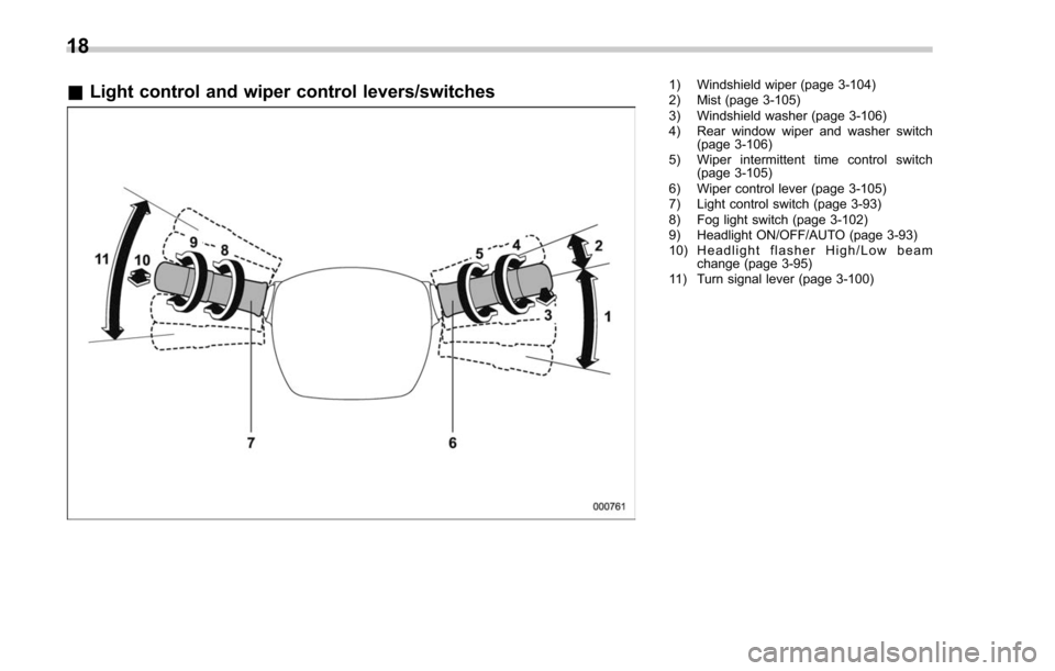
&Light control and wiper control levers/switches1) Windshield wiper (page 3-104)
2) Mist (page 3-105)
3) Windshield washer (page 3-106)
4) Rear window wiper and washer switch
(page 3-106)
5) Wiper intermittent time control switch (page 3-105)
6) Wiper control lever (page 3-105)
7) Light control switch (page 3-93)
8) Fog light switch (page 3-102)
9) Headlight ON/OFF/AUTO (page 3-93)
10) Headlight flasher High/Low beam change (page 3-95)
11) Turn signal lever (page 3-100)
18
Page 28 of 634
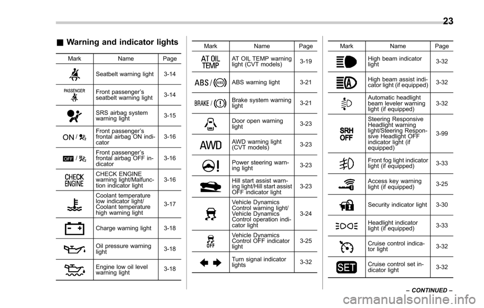
&Warning and indicator lights
Mark Name Page
Seatbelt warning light 3-14
Front passenger’s
seatbelt warning light 3-14
SRS airbag system
warning light3-15
/Front passenger
’s
frontal airbag ON indi-
cator 3-16
/Front passenger
’s
frontal airbag OFF in-
dicator 3-16
CHECK ENGINE
warning light/Malfunc-
tion indicator light3-16
Coolant temperature
low indicator light/
Coolant temperature
high warning light3-17
Charge warning light 3-18
Oil pressure warning
light
3-18
Engine low oil level
warning light3-18Mark Name Page
AT OIL TEMP warning
light (CVT models)
3-19
ABS warning light 3-21
Brake system warning
light
3-21
Door open warning
light3-23
AWD warning light
(CVT models)
3-23
Power steering warn-
ing light3-23
Hill start assist warn-
ing light/Hill start assist
OFF indicator light3-23
Vehicle Dynamics
Control warning light/
Vehicle Dynamics
Control operation indi-
cator light3-24
Vehicle Dynamics
Control OFF indicator
light
3-25
Turn signal indicator
lights
3-32Mark Name Page
High beam indicator
light
3-32
High beam assist indi-
cator light (if equipped)3-32
Automatic headlight
beam leveler warning
light (if equipped)3-32
Steering Responsive
Headlight warning
light/Steering Respon-
sive Headlight OFF
indicator light (if
equipped)3-99
Front fog light indicator
light (if equipped)
3-33
Access key warning
light (if equipped)3-25
Security indicator light 3-30
Headlight indicator
light (if equipped)
3-33
Cruise control indica-
tor light3-32
Cruise control set in-
dicator light3-32
– CONTINUED –
23
Page 117 of 634
Keys and doors/Keyless access with push–button start system
on a cell phone, the operating ranges may
be reduced, or the keyless access func-
tion may not operate.
In such a case, perform the procedure
described in “Locking and unlocking ”F 9-
17.
. When an access key is in the operating
range, if the door handle becomes wet
due to exposure to a significant amount of
water when the vehicle is washed or
during heavy rain, the doors may be
locked or unlocked.
. The keyless access function may not
operate properly depending on the status
of the access key and the radio wave
conditions around the vehicle. In such a
case, perform the procedure described in
“ Locking and unlocking ”F 9-17.
! How to use keyless access func-
tions
! Keyless access function tips
. When you lock the doors and rear gate
using the keyless access function, turn the
push-button ignition switch off. It is not
possible to lock the doors and rear gate
using the keyless access function when
the push-button ignition switch is on the
“ACC ”or “ON ”position. Refer to “Switch-
ing power status ”F 3-7.
. If the door handle is gripped with a
gloved hand, the door lock may not be released.
.
If the door lock sensor is touched three
times or more repeatedly, the system will
ignore the sensor operation.
. When performing the locking proce-
dure too quickly, locking may not have
been completed. After performing the
locking procedure, it is recommended to
pull the REAR door handle to confirm that
the doors have been locked.
. It is possible to lock the doors even
when one of the doors is open. After
performing the locking procedure, close
the opened door or rear gate to lock it.
. Within 3 seconds after locking the
doors and the rear gate by using the
keyless access function, it is not possible
to unlock doors and/or the rear gate by
using the keyless access function.
. When locking, be sure to carry the
access key to prevent locking the access
key in the vehicle.
. The setting of the hazard warning
flasher operation and the volume of the
audible signal can be changed by your
SUBARU dealer. Contact your SUBARU
dealer for details.
. For models with the multi function
display, the setting of the hazard warning
flasher operation can be changed by
operating the multi function display. For
details, refer to “Hazard warning flasher setting
”F 3-82.
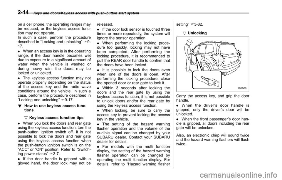
! Unlocking
Carry the access key, and grip the door
handle.
. When the driver ’s door handle is
gripped, only the driver ’s door will be
unlocked.
. When the front passenger ’s door han-
dle is gripped, all doors including the rear
gate will be unlocked.
Also, an electronic chirp will sound twice
and the hazard warning flashers will flash
twice.
2-14
Page 119 of 634
Keys and doors/Keyless access with push–button start system
system have not been used for 2 weeks or
longer while all doors are locked
To recover the keyless access func-
tion:
Operate one of the following items.
–Turn the ignition switch to the “ON”
position
– Unlock the doors by operating any
procedure other than gripping the front
passenger ’s door handle
– Lock the doors
– Open a door and then close it
. Case 2 : When the access key has
been left in the operating range for 10
minutes or longer while all doors are
locked
To recover the keyless access func-
tion:
Operate one of the following items.
–Unlock the doors by gripping the
door handle
– Unlock the doors by pressing the
rear gate opener button
– Lock the doors by touching the door
lock sensor
– Lock or unlock the doors by using
the remote keyless entry system
– Lock or unlock the doors by using
the power door locking switch
– Open either of the front doors !
Door unlock selection function
The door unlock selection function makes
it possible to unlock the driver ’s door or
the rear gate without unlocking any other
doors. You can change the setting for the
driver ’s door and for the rear gate inde-
pendently.
Operational: Only the driver ’s door or the
rear gate will be unlocked.
Non-operational: All doors and the rear
gate will be unlocked.
For the factory setting (default setting),
refer to “Function settings” F25.
NOTE
The setting can be changed by your
SUBARU dealer. Contact your SUBARU
dealer for details. Also, for models with
the multi function display, the setting
can be changed by operating the multi
function display. For details, refer to
“Keyless access setting (models with
“ keyless access with push-button start
system ”)” F 3-86.
& Selecting audible signal op-
eration
Using an electronic chirp, the system will
give you an audible signal when the doors
lock and unlock. If desired, you may turn
the audible signal off. For more details,
contact a SUBARU dealer.
NOTE
For models with the multi function
display, the setting can be changed by
operating the multi function display.
For details, refer to “Keyless buzzer
volume setting ”F 3-81.
& Warning chimes and warning
light
The keyless access with push-button start
system sounds a warning chime and
flashes the access key warning light on
the combination meter in order to minimize
improper operations and help protect your
vehicle from theft.
For details, refer to “Warning chimes and
warning light of the keyless access with
push-button start system ”F 3-25.
2-16
Page 127 of 634
Keys and doors/Remote keyless entry system
&Sounding a panic alarm
To activate the alarm, press the “PANIC”
button once.
The horn will sound and the hazard
warning flashers will flash.
To deactivate the panic alarm, press any
button on the access key/remote transmit-
ter. Unless a button on the access key/
remote transmitter is pressed, the alarm
will be deactivated after approximately 30
seconds.
& Selecting audible signal op-
eration (models without
“keyless access with push-
button start system ”)
Using an electronic chirp, the system will
give you an audible signal when the doors
lock and unlock. If desired, you may turn
the audible signal off.
Perform the following steps to deactivate
the audible signal. You can also use the
same steps to restore the function.
1. Sit in the driver ’s seat and shut all
doors and the rear gate.
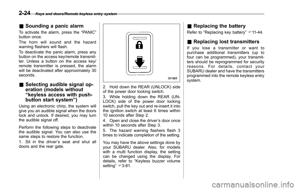
2. Hold down the REAR (UNLOCK) side
of the power door locking switch.
3. While holding down the REAR (UN-
LOCK) side of the power door locking
switch, pull the key out and re-insert it into
the ignition switch at least 6 times within
10 seconds after Step 2.
4. Open and close the driver ’s door once
within 10 seconds after Step 3.
5. The hazard warning flashers flash 3
times to indicate completion of the setting.
You may have the above settings done by
your SUBARU dealer. Also, for models
with a multi function display, the setting
can be changed using the display. For
details, refer to “Keyless buzzer volume
setting ”F 3-81.
& Replacing the battery
Refer to “Replacing key battery ”F 11-44.
& Replacing lost transmitters
If you lose a transmitter or want to
purchase additional transmitters (up to
four can be programmed), your transmit-
ters should be reprogrammed for security
reasons. For details, contact your
SUBARU dealer and have the transmitters
programmed into the remote keyless entry
system.
2-24
Page 152 of 634
Ignition switch (models without push-button start system) ......................................... 3-4
LOCK.................................................................. 3-4
ACC.................................................................... 3-5
ON...................................................................... 3-5
START ................................................................ 3-5
Key reminder chime ............................................ 3-5
Ignition switch light (if equipped) ......................... 3-6
Push-button ignition switch (models with
push-button start system) ............................... 3-6
Safety precautions.............................................. 3-6
Operating range for push-button start system ...... 3-6
Switching power status ....................................... 3-7
When access key does not operate properly ........ 3-8
Hazard warning flasher....................................... 3-8
Meters and gauges. ............................................. 3-9
Combination meter illumination ........................... 3-9
Canceling the function for meter/gauge needle movement upon turning on the ignition
switch ............................................................... 3-9
Speedometer ...................................................... 3-10
Odometer ........................................................... 3-10
Double trip meter ............................................... 3-10
Tachometer ........................................................ 3-11
Fuel gauge ......................................................... 3-12
ECO gauge (if equipped) .................................... 3-12
Warning and indicator lights ............................. 3-13Seatbelt warning light and chime ........................ 3-14
SRS airbag system warning light ........................ 3-15
Front passenger ’s frontal airbag ON and OFF
indicators ......................................................... 3-16 CHECK ENGINE warning light/Malfunction
indicator light .................................................. 3-16
Coolant temperature low indicator light/Coolant temperature high warning light ......................... 3-17
Charge warning light .......................................... 3-18
Oil pressure warning light .................................. 3-18
Engine low oil level warning light ....................... 3-18
Windshield washer fluid warning light ................ 3-19
AT OIL TEMP warning light (CVT models) ........... 3-19
Low tire pressure warning light (U.S.-spec. models) ........................................................... 3-19
ABS warning light .............................................. 3-21
Brake system warning light ................................ 3-21
Low fuel warning light ....................................... 3-22
Hill start assist warning light/Hill start assist OFF indicator light .................................................. 3-23
Door open warning light .................................... 3-23
All-Wheel Drive warning light (CVT models) ... ..... 3-23
Power steering warning light .............................. 3-23
Vehicle Dynamics Control warning light/Vehicle Dynamics Control operation indicator light .. ..... 3-24
Vehicle Dynamics Control OFF indicator light ..... 3-25
Warning chimes and warning light of the keyless access with push-button start system (if
equipped) ........................................................ 3-25
Security indicator light ....................................... 3-30
SI-DRIVE indicator light (if equipped) .................. 3-31
Select lever/gear position indicator (CVT models) ........................................................... 3-31
Turn signal indicator lights ................................. 3-32
High beam indicator light ................................... 3-32
High beam assist indicator light (if equipped) ..... 3-32
Instruments and controls
3
Page 153 of 634
Instruments and controls
Cruise control indicator light (if equipped).......... 3-32
Cruise control set indicator light (if equipped) ......................................................... 3-32
Automatic headlight beam leveler warning light (if equipped) ......................................................... 3-32
Steering Responsive Headlight warning light/ Steering Responsive Headlight OFF indicator
light (if equipped) ............................................. 3-33
Front fog light indicator light (if equipped) .......... 3-33
Headlight indicator light (if equipped) ................. 3-33
X-mode indicator light (if equipped) .................... 3-33
Hill descent control indicator light (if equipped) ......................................................... 3-33
Steering responsive fog lights warning indicator/ Steering responsive fog lights OFF indicator (if
equipped) ......................................................... 3-33
BSD/RCTA warning indicator (if equipped) .......... 3-33
BSD/RCTA OFF indicator (if equipped) ................ 3-34
RAB warning light (if equipped) .......................... 3-34
RAB OFF indicator light (if equipped) .................. 3-34
Information display (Mexico-spec. models) ...... 3-34Outside temperature indicator............................ 3-34
Driving information display ................................. 3-35
Clock ................................................................. 3-38
Multi information display (models with type
B combination meter) ..................................... 3-39
Basic operation.................................................. 3-40
Welcome screen and Good-bye screen ............... 3-40
Warning screen .................................................. 3-41
Basic screens .................................................... 3-41
Menu screens .................................................... 3-42
Multi function display (if equipped) .................. 3-44Basic operation................................................. 3-45
Welcome screen ................................................ 3-45
Ending screen ................................................... 3-46
Self-check screen .............................................. 3-46
Interruption screen ............................................ 3-48
Basic screens .................................................... 3-48
Selection screen ................................................ 3-56
Date and time settings ....................................... 3-59
Image quality and volume settings ..................... 3-66
Screen settings. ................................................. 3-68
Maintenance settings ......................................... 3-76
Driving history registration ................................. 3-79
Car settings ....................................................... 3-80
Initialize ............................................................. 3-90
Light control switch ........................................... 3-93Headlights......................................................... 3-93
High/low beam change (dimmer) ... ..................... 3-95
Headlight flasher ............................................... 3-98
Daytime running light system ............................. 3-98
Steering Responsive Headlight (SRH) (if
equipped) ........................................................ 3-99
SRH OFF switch ................................................ 3-99
Turn signal lever .............................................. 3-100One-touch lane changer ................................... 3-101
Illumination brightness control ....................... 3-101
Headlight beam leveler (if equipped) ............. 3-102
Automatic headlight beam leveler (models with
LED headlights) ............................................. 3-102
Page 159 of 634
Instruments and controls/Hazard warning flasher
!Battery drainage prevention func-
tion
When the push-button ignition switch is
left in the “ACC”or “ON ”position for
approximately 1 hour, the push-button
ignition switch will be automatically
switched to “OFF”to prevent the battery
from going dead. This function is activated
when the select lever is in the “P ”position.
& When access key does not
operate properly
Refer to “Access key –if access key does
not operate properly ”F 9-17.
Hazard warning flasher
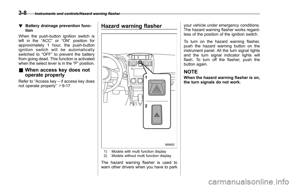
1) Models with multi function display
2) Models without multi function display
The hazard warning flasher is used to
warn other drivers when you have to park your vehicle under emergency conditions.
The hazard warning flasher works regard-
less of the position of the ignition switch.
To turn on the hazard warning flasher,
push the hazard warning button on the
instrument panel. All the turn signal lights
and the turn signal indicator lights will
flash. To turn off the flasher, push the
button again.
NOTE
When the hazard warning flasher is on,
the turn signals do not work.
3-8
Page 171 of 634
Instruments and controls/Warning and indicator lights
as the malfunction exists. When the
malfunction indicator is illuminated, the
system may not be able to detect or signal
low tire pressure as intended. TPMS
malfunctions may occur for a variety of
reasons, including the installation of re-
placement or alternate tires or wheels on
the vehicle that prevent the TPMS from
functioning properly. Always check the
TPMS malfunction telltale after replacing
one or more tires or wheels on your
vehicle to ensure that the replacement or
alternate tires and wheels allow the TPMS
to continue to function properly.
Should the warning light illuminate stea-
dily after blinking for approximately one
minute, have the system inspected by
your nearest SUBARU dealer as soon as
possible.
WARNING
If this light does not illuminate
briefly after the ignition switch is
turned ON or the light illuminates
steadily after blinking for approxi-
mately one minute, you should have
your Tire Pressure Monitoring Sys-
tem checked at a SUBARU dealer as
soon as possible.
If this light illuminates while driving,
never brake suddenly and keepdriving straight ahead while gradu-
ally reducing speed. Then slowly
pull off the road to a safe place.
Otherwise an accident involving
serious vehicle damage and serious
personal injury could occur.
If this light still illuminates while
driving after adjusting the tire pres-
sure, a tire may have significant
damage and a fast leak that causes
the tire to lose air rapidly. If you have
a flat tire, replace it with a spare tire
as soon as possible.
When a spare tire is mounted or a
wheel rim is replaced without the
original pressure sensor/transmitter
being transferred, the Low tire pres-
sure warning light will illuminate
steadily after blinking for approxi-
mately one minute. This indicates
the TPMS is unable to monitor all
four road wheels. Contact your
SUBARU dealer as soon as possible
for tire and sensor replacement and/
or system resetting.
If the light illuminates steadily after
blinking for approximately one min-
ute, promptly contact a SUBARU
dealer to have the system inspected.
CAUTION
The tire pressure monitoring system
is NOT a substitute for manually
checking tire pressure. The tire
pressure should be checked peri-
odically (at least monthly) using a
tire gauge. After any change to tire
pressure(s), the tire pressure mon-
itoring system will not re-check tire
inflation pressures until the vehicle
is first driven more than 25 mph (40
km/h). After adjusting the tire pres-
sures, increase the vehicle speed to
at least 25 mph (40 km/h) to start the
TPMS re-checking of the tire infla-
tion pressures. If the tire pressures
are now above the severe low
pressure threshold, the low tire
pressure warning light should turn
off a few minutes later. Therefore, be
sure to install the specified size for
the front and rear tires.
3-20
Page 183 of 634
Instruments and controls/Warning and indicator lights
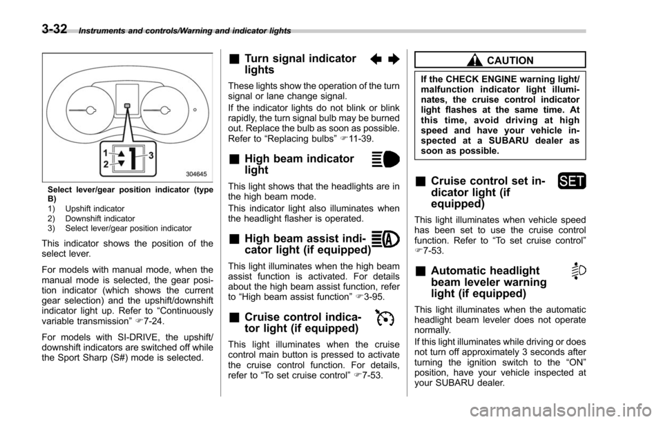
Select lever/gear position indicator (type
B)
1) Upshift indicator
2) Downshift indicator
3) Select lever/gear position indicator
This indicator shows the position of the
select lever.
For models with manual mode, when the
manual mode is selected, the gear posi-
tion indicator (which shows the current
gear selection) and the upshift/downshift
indicator light up. Refer to“Continuously
variable transmission ”F 7-24.
For models with SI-DRIVE, the upshift/
downshift indicators are switched off while
the Sport Sharp (S#) mode is selected.
&Turn signal indicator
lights
These lights show the operation of the turn
signal or lane change signal.
If the indicator lights do not blink or blink
rapidly, the turn signal bulb may be burned
out. Replace the bulb as soon as possible.
Refer to “Replacing bulbs ”F 11-39.
&High beam indicator
light
This light shows that the headlights are in
the high beam mode.
This indicator light also illuminates when
the headlight flasher is operated.
&High beam assist indi-
cator light (if equipped)
This light illuminates when the high beam
assist function is activated. For details
about the high beam assist function, refer
to “High beam assist function ”F 3-95.
&Cruise control indica-
tor light (if equipped)
This light illuminates when the cruise
control main button is pressed to activate
the cruise control function. For details,
refer to “To set cruise control ”F 7-53.
CAUTION
If the CHECK ENGINE warning light/
malfunction indicator light illumi-
nates, the cruise control indicator
light flashes at the same time. At
this time, avoid driving at high
speed and have your vehicle in-
spected at a SUBARU dealer as
soon as possible.
&Cruise control set in-
dicator light (if
equipped)
This light illuminates when vehicle speed
has been set to use the cruise control
function. Refer to “To set cruise control ”
F 7-53.
&Automatic headlight
beam leveler warning
light (if equipped)
This light illuminates when the automatic
headlight beam leveler does not operate
normally.
If this light illuminates while driving or does
not turn off approximately 3 seconds after
turning the ignition switch to the “ON”
position, have your vehicle inspected at
your SUBARU dealer.
3-32