SUBARU IMPREZA 2006 2.G Owners Manual
Manufacturer: SUBARU, Model Year: 2006, Model line: IMPREZA, Model: SUBARU IMPREZA 2006 2.GPages: 365, PDF Size: 7.09 MB
Page 111 of 365
2-24 Keys and doors
NOTE
If the rear gate cannot be unlocked due
to a discharged battery, a fault in the
door locking/unlocking system or oth-
er causes, you can unlock it by manu-
ally operating the rear gate lock release
lever.
For the procedure, refer to Rear gate
if the rear gate cannot be unlocked in
chapter 9 In case of emergency .
Moonroof (if equipped)
The moonroof has both tilting and sliding
functions.
The moonroof operates only when the ig-
nition switch is in the ON position.
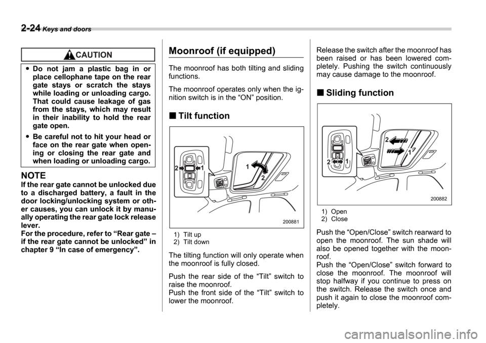
Tilt function
1) Tilt up
2) Tilt down
The tilting function will only operate when
the moonroof is fully closed.
Push the rear side of the Tilt switch to
raise the moonroof.
Push the front side of the Tilt switch to
lower the moonroof. Release the switch after the moonroof has
been raised or has been lowered com-
pletely. Pushing the switch continuously
may cause damage to the moonroof.
Sliding function
1) Open
2) Close
Push the Open/Close switch rearward to
open the moonroof. The sun shade will
also be opened together with the moon-
roof.
Push the Open/Close switch forward to
close the moonroof. The moonroof will
stop halfway if you continue to press on
the switch. Release the switch once and
push it again to close the moonroof com-
pletely.
Do not jam a plastic bag in or
place cellophane tape on the rear
gate stays or scratch the stays
while loading or unloading cargo.
That could cause leakage of gas
from the stays, which may result
in their inability to hold the rear
gate open.
Be careful not to hit your head or
face on the rear gate when open-
ing or closing the rear gate and
when loading or unloading cargo.
1
21
2
200881
2
1
12
200882
Page 112 of 365
Keys and doors 2-25
After washing the vehicle or after it rains,
wipe away water on the roof prior to open-
ing the moonroof to prevent drops of water
from falling into the passenger compart-
ment.
NOTE
If the moonroof cannot be closed
through switch operation because of
system failure, it can be closed manu-
ally using a hex-head wrench. For the
procedure, refer to Moonroof if the
moonroof cannot be closed section in
chapter 9 In case of emergency .
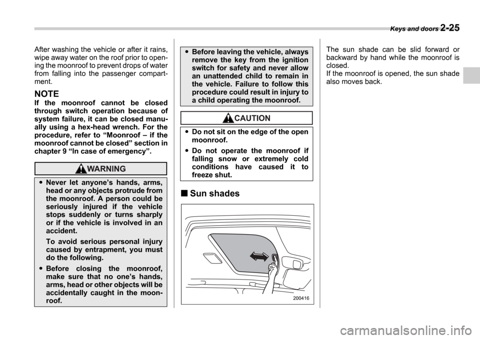
Sun shades
The sun shade can be slid forward or
backward by hand while the moonroof is
closed.
If the moonroof is opened, the sun shade
also moves back.
Never let anyone s hands, arms,
head or any objects protrude from
the moonroof. A person could be
seriously injured if the vehicle
stops suddenly or turns sharply
or if the vehicle is involved in an
accident.
To avoid serious personal injury
caused by entrapment, you must
do the following.
Before closing the moonroof,
make sure that no one s hands,
arms, head or other objects will be
accidentally caught in the moon-
roof.
Before leaving the vehicle, always
remove the key from the ignition
switch for safety and never allow
an unattended child to remain in
the vehicle. Failure to follow this
procedure could result in injury to
a child operating the moonroof.
Do not sit on the edge of the open
moonroof.
Do not operate the moonroof if
falling snow or extremely cold
conditions have caused it to
freeze shut.
200416
Page 113 of 365

Page 114 of 365

3
Instruments and controls
Ignition switch .................................................... 3-3
LOCK .............................................. ......................... 3-3
ACC ............................................... ........................... 3-4
ON ................................................ ............................ 3-4
START ............................................. ......................... 3-4
Key reminder chime ................................ ............... 3-5
Ignition switch light ............................. ................... 3-5
Key interlock release (AT vehicles only) .......... .... 3-5
Hazard warning flasher ............................ .......... 3-6
Meters and gauges (WRX-STI) ....................... ... 3-6
Combination meter illumination .................... ........ 3-6
Cancelling sequential illumination of the combination meter ................................. .............. 3-6
Speedometer ....................................... .................... 3-6
Odometer/Trip meter ............................... ............... 3-7
Tachometer ........................................ ..................... 3-7
Fuel gauge ........................................ ....................... 3-8
Temperature gauge ................................. ............... 3-8
Outside temperature indicator ..................... ......... 3-9
REV indicator light and buzzer (WRX-STI) ....... 3-9 Setting the alarm-level engine speed .............. ..... 3-10
Deactivating the REV alarm system ................. ..... 3-11
Meters and gauges (Except WRX-STI) ............. 3-1 1
Speedometer ....................................... .................... 3-11
Odometer/Trip meter ............................... ............... 3-11
Tachometer ........................................ ..................... 3-12
Fuel gauge ........................................ ....................... 3-12
Temperature gauge ................................. ............... 3-13
Outside temperature indicator ..................... ......... 3-13Warning and indicator lights ......................
....... 3-14
Seatbelt warning light and chime .................. ........ 3-14
SRS airbag system warning light ................... ....... 3-15
Front passenger s frontal airbag ON and OFF
indicators ........................................ ...................... 3-15
CHECK ENGINE warning light/Malfunction indicator lamp .................................... ................... 3-16
Charge warning light .............................. ................ 3-16
Oil pressure warning light ........................ ............. 3-16
AT OIL TEMPerature warning light (AT vehicles) ..................................... .................... 3-17
Rear differential oil temperature warning light (WRX-STI) ......................................... ..................... 3-17
ABS warning light ................................. .................. 3-17
Brake system warning light ........................ ........... 3-18
Door open warning light ........................... ............. 3-19
All-Wheel Drive warning light (AWD AT vehicles
if equipped) ..................................... ................... 3-19
Intercooler water spray warning light (WRX-STI) ......................................... ..................... 3-19
Selector lever position indicator (AT vehicles) ... . 3-20
Turn signal indicator lights ...................... .............. 3-20
High beam indicator light ......................... .............. 3-20
Cruise control indicator light .................... ............. 3-20
Cruise control set indicator light ................ .......... 3-20
Driver s control center differential auto indicator
light (WRX-STI) ................................... .................. 3-20
Driver s control center differential indicator and
warning lights (WRX-STI) .......................... .......... 3-21
Headlight indicator light (WRX-STI) ............... ....... 3-21
REV indicator light (WRX-STI) ..................... .......... 3-21
Page 115 of 365

Instruments and controls
Clock .................................................................... 3-22
Light control switch .............................. ............. 3-22
Headlights ........................................ ....................... 3-22
High/low beam change (dimmer) ..................... ..... 3-23
Headlight flasher ................................. ................... 3-23
Daytime running light system ...................... ......... 3-23
Turn signal lever ................................. ................ 3-24
Illumination brightness control ................... ...... 3-25
Headlight beam leveler (U.S.-spec. WRX-STI) .............................. ........ 3-25
Parking light switch .............................. ............. 3-25
Front fog light button (if equipped) .............. .... 3-26
Wiper and washer .................................. ............. 3-26
Windshield wiper and washer switches .............. . 3-27
Rear window wiper and washer switch Wagon ............................................ .................... 3-28
Rear window defogger button ....................... .... 3-29
Windshield wiper deicer (if equipped) ............. . 3-30
Intercooler water spray switch (WRX-STI) ....... 3-3 1
Mirrors ........................................... ...................... 3-32
Inside mirror ..................................... ...................... 3-32
Outside mirrors ................................... .................... 3-33
Tilt steering wheel ............................... ............... 3-35
Horn .............................................. ....................... 3-35
Page 116 of 365
Instruments and controls 3-3
CONTINUED
Instrum ents and controlsIgnition switch
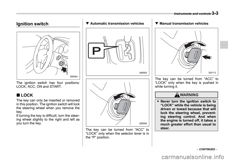
The ignition switch has four positions:
LOCK, ACC, ON and START.
LOCK
The key can only be inserted or removed
in this position. The ignition switch will lock
the steering wheel when you remove the
key.
If turning the key is difficult, turn the steer-
ing wheel slightly to the right and left as
you turn the key.
Automatic transmission vehicles
The key can be turned from ACC to
LOCK only when the selector lever is in
the P position.Manual transmission vehicles
The key can be turned from ACC to
LOCK only when the key is pushed in
while turning it.
300564
300565
300566
Never turn the ignition switch to LOCK while the vehicle is being
driven or towed because that will
lock the steering wheel, prevent-
ing steering control. And when
the engine is turned off, it takes a
much greater effort than usual to
steer.
300115
Page 117 of 365
3-4 Instruments and controls
NOTE
Keep the ignition switch in the
LOCK position when the engine is
not running.
Using electrical accessories for a
long time with the ignition switch in the ON or ACC position can cause the
battery to go dead.
If the ignition switch will not move from
the LOCK position to the ACC po-
sition, turn the steering wheel slightly
to the left and right as you turn the ig-
nition switch.
If the key is attached to a keyholder
or to a large bunch of other keys, cen-
trifugal force may act on it as the vehi-
cle moves, resulting in unwanted turn-
ing of the ignition switch. Also, if a
large keyholder is attached to the key,
your knees or hands may accidentally
touch it in a way that turns the ignition switch.
ACC
In this position the electrical accessories
(radio, cigarette lighter, etc.) can be used.
ON
This is the normal operating position after
the engine is started.
START
The engine is started in this position. The
starter cranks the engine to start it. When
the key is released (after the engine has
started), the key automatically returns to
the
ON position.
For vehicle with immobilizer
If your registered key fails to start the en-
gine, pull out the key once (the security in-
dicator light will blink), and then insert the
key in the ignition switch and turn it to the START position and again try to start the
engine.
NOTE
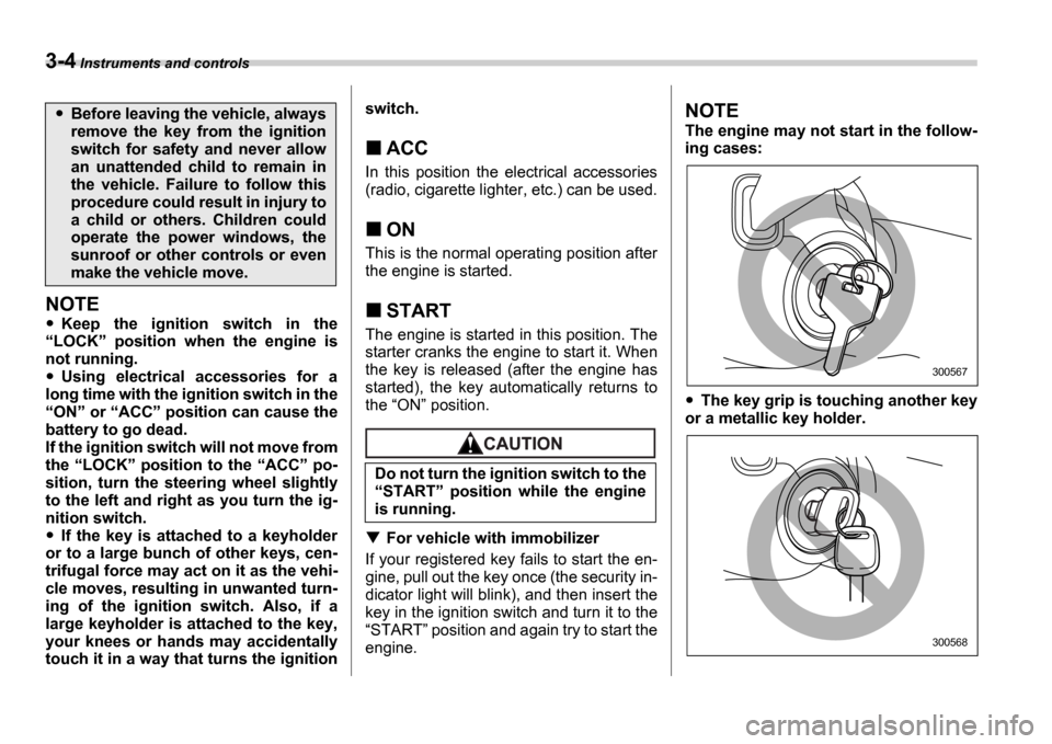
The engine may not start in the follow-
ing cases:
The key grip is touching another key
or a metallic key holder.
Before leaving the vehicle, always
remove the key from the ignition
switch for safety and never allow
an unattended child to remain in
the vehicle. Failure to follow this
procedure could result in injury to
a child or others. Children could
operate the power windows, the
sunroof or other controls or even
make the vehicle move.
Do not turn the ignition switch to the START position while the engine
is running.
300567
300568
Page 118 of 365
Instruments and controls 3-5
The key is near another key that con-
tains an immobilizer transponder.
Key reminder chime
The reminder chime sounds when the
driver s door opens and the key is in the
LOCK or ACC positions. The chime
stops when the key is removed from the
ignition switch.
Ignition switch light
For easy access to the ignition switch in
the dark, the ignition switch light comes on
when driver s door is opened. The light re-
mains on for 10 seconds and goes out af-
ter driver s door is closed or if the key is
turned to the ON position.
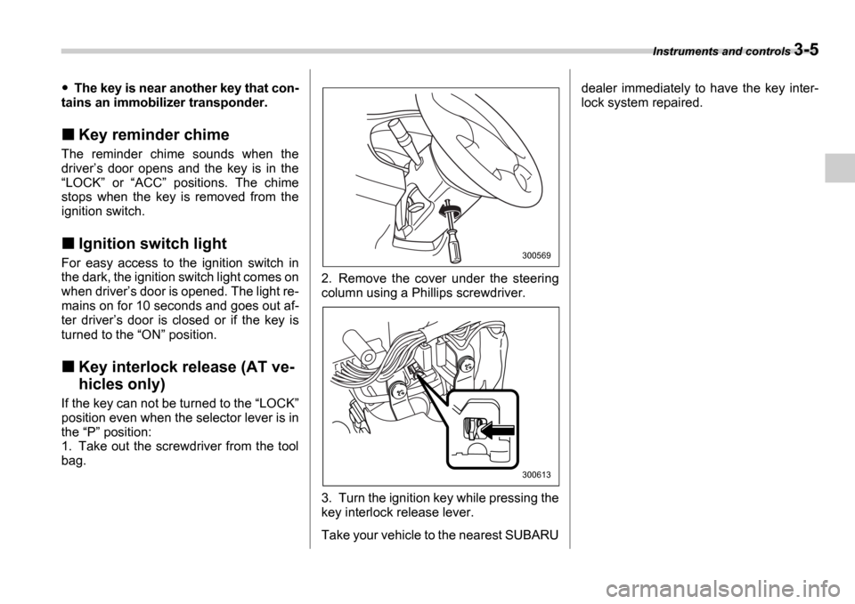
Key interlock release (AT ve-
hicles only)
If the key can not be turned to the LOCK
position even when the selector lever is in
the P position:
1. Take out the screwdriver from the tool
bag. 2. Remove the cover under the steering
column using a Phillips screwdriver.
3. Turn the ignition key while pressing the
key interlock release lever.
Take your vehicle to the nearest SUBARUdealer immediately to have the key inter-
lock system repaired.
300569
300613
Page 119 of 365
3-6 Instruments and controls
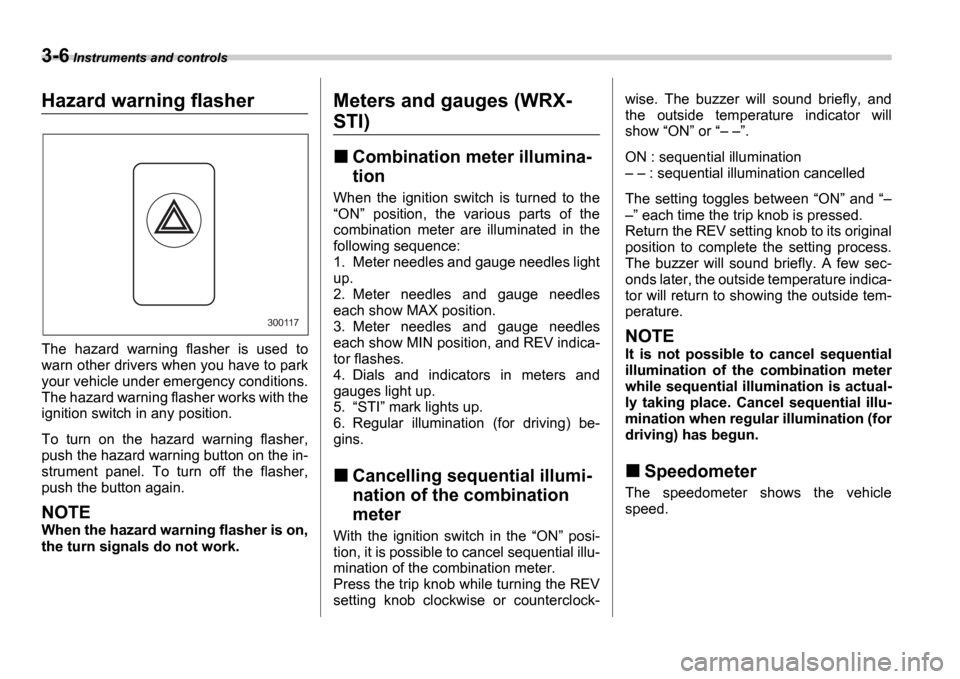
Hazard warning flasher
The hazard warning flasher is used to
warn other drivers when you have to park
your vehicle under emergency conditions.
The hazard warning flasher works with the
ignition switch in any position.
To turn on the hazard warning flasher,
push the hazard warning button on the in-
strument panel. To turn off the flasher,
push the button again.
NOTE
When the hazard warning flasher is on,
the turn signals do not work.
Meters and gauges (WRX-
STI)
Combination meter illumina-
tion
When the ignition switch is turned to the ON position, the various parts of the
combination meter are illuminated in the
following sequence:
1. Meter needles and gauge needles light
up.
2. Meter needles and gauge needles
each show MAX position.
3. Meter needles and gauge needles
each show MIN position, and REV indica-
tor flashes.
4. Dials and indicators in meters and
gauges light up.
5. STI mark lights up.
6. Regular illumination (for driving) be-
gins.
Cancelling sequential illumi-
nation of the combination
meter
With the ignition switch in the ON posi-
tion, it is possible to cancel sequential illu-
mination of the combination meter.
Press the trip knob while turning the REV
setting knob clockwise or counterclock- wise. The buzzer will sound briefly, and
the outside temperature indicator will
show
ON or .
ON : sequential illumination : sequential illumination cancelled
The setting toggles between ON and
each time the trip knob is pressed.
Return the REV setting knob to its original
position to complete the setting process.
The buzzer will sound briefly. A few sec-
onds later, the outside temperature indica-
tor will return to showing the outside tem-
perature.
NOTE
It is not possible to cancel sequential
illumination of the combination meter
while sequential illumination is actual-
ly taking place. Cancel sequential illu-
mination when regular illumination (for
driving) has begun.
Speedometer
The speedometer shows the vehicle
speed.
300117
Page 120 of 365
Instruments and controls 3-7
CONTINUED
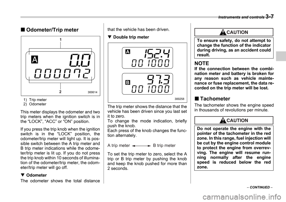
Odometer/Trip meter
1) Trip meter
2) Odometer
This meter displays the odometer and two
trip meters when the ignition switch is in
the LOCK , ACC or ON position.
If you press the trip knob when the ignition
switch is in the LOCK position, the
odometer/trip meter will light up. It is pos-
sible switch between the A trip meter and
B trip meter indications while the odome-
ter/trip meter is lit up. If you do not press
the trip knob within 10 seconds of illumina-
tion of the odometer/trip meter, the odom-
eter/trip meter will go off.
Odometer
The odometer shows the total distance that the vehicle has been driven.
Double trip meter
The trip meter shows the distance that the
vehicle has been driven since you last set
it to zero.
To change the mode indication, briefly
push the knob.
Each press of the knob changes the func-
tion alternately.
To set the trip meter to zero, select the A
trip or B trip meter by pushing the knob
and keep the knob pushed for more than
2 seconds.
NOTE
If the connection between the combi-
nation meter and battery is broken for
any reason such as vehicle mainte-
nance or fuse replacement, the data re-
corded on the trip meter will be lost.
Tachometer
The tachometer shows the engine speed
in thousands of revolutions per minute.
1
2
300614
300258
A trip meter B trip meter
To ensure safety, do not attempt to
change the function of the indicator
during driving, as an accident could
result.
Do not operate the engine with the
pointer of the tachometer in the red
zone. In this range, fuel injection will
be cut by the engine control module
to protect the engine from overrev-
ving. The engine will resume run-
ning normally after the engine
speed is reduced below the red
zone.