temp SUBARU IMPREZA 2016 5.G User Guide
[x] Cancel search | Manufacturer: SUBARU, Model Year: 2016, Model line: IMPREZA, Model: SUBARU IMPREZA 2016 5.GPages: 594, PDF Size: 5.36 MB
Page 143 of 594
Keys and doors/Moonroof
firmly until the latch engages.
The rear gate can be lowered easily if you
pull it down holding the recessed grip.
WARNING
.To prevent dangerous exhaust
gas from entering the vehicle,
always keep the rear gate closed
while driving.
. Do not attempt to shut the rear
gate while holding the recessed
grip. Also avoid closing the rear
gate by pulling on the recessed
grip from inside the cargo space.
There is a danger of your hand
being caught and injured.
CAUTION
. Do not jam a plastic bag in or
place cellophane tape on the rear
gate stays or scratch the stays
while loading or unloading cargo.
That could cause leakage of gas
from the stays, which may result
in their inability to hold the rear
gate open.
. Be careful not to hit your head or
face on the rear gate when open-
ing or closing the rear gate and when loading or unloading car-
go.
NOTE
If the rear gate cannot be unlocked due
to a discharged vehicle battery, a
malfunction in the door locking/unlock-
ing system or other causes, you can
unlock it by manually operating the
rear gate lock release lever. For the
procedure, refer to
“Rear gate–if the
rear gate cannot be opened ”F 9-19.
Moonroof (if equipped)
WARNING
Never let anyone ’shands,arms,
head or any objects protrude from
the moonroof. A person could be
seriously injured if any of the follow-
ing conditions occur.
. The vehicle stops suddenly.
. The vehicle turns sharply.
. The vehicle is involved in an
accident.
. Body parts protruding from the
vehicle are struck by outside
objects.
To avoid serious personal injury
caused by entrapment, always con-
form to the following instructions
without exception.
. Before closing the moonroof,
make sure that no one ’s hands,
arms, head or other objects will
be accidentally caught in the
moonroof.
. Always carry the key when you
leave the vehicle for safety rea-
sons and never allow an unat-
tended child to remain in the
2-42
Page 145 of 594
Keys and doors/Moonroof
“OPEN/CLOSE”switch.
To stop the moonroof at a selected mid-
way position while opening or closing it,
momentarily push the switch to the
“OPEN” side or“CLOSE ”side.
After washing the vehicle or after it rains,
wipe away water on the roof prior to
opening the moonroof to prevent drops
of water from falling into the passenger
compartment.
NOTE
Driving with the moonroof fully open
can cause an annoying sound to be
generated at high speeds. If this oc-
curs, use the moonroof at the initial
stop position of 1.6 in (4 cm) away from
the fully opened position.
! Anti-entrapment function
When the moonroof senses a substantial
enough object trapped between its glass
and the vehicle’ s roof during closure, it
automatically moves back to the fully open
position and stops there. The anti-entrap-
ment function may also be activated by a
strong shock on the moonroof even when
there is nothing trapped.
CAUTION
Never attempt to test this function
using fingers, hands or other parts
of your body.
NOTE
For the sake of safety, it is recom-
mended that you avoid driving with the
moonroof fully opened.
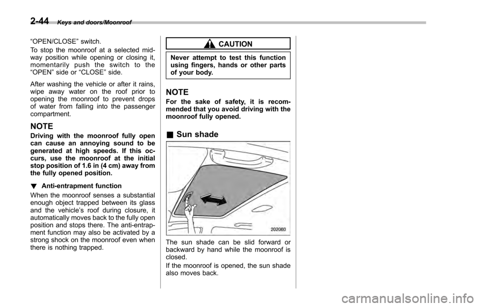
& Sun shade
The sun shade can be slid forward or
backward by hand while the moonroof is
closed.
If the moonroof is opened, the sun shade
also moves back.
2-44
Page 146 of 594

Ignition switch (models without“keyless
access with push-button start system ”)......... 3-4
LOCK .................................................................. 3-4
ACC.................................................................... 3-5
ON...................................................................... 3-5
START ................................................................ 3-5
Key reminder chime ............................................ 3-5
Ignition switch light (if equipped) ......................... 3-6
Push-button ignition switch (models with
push-button start system) ............................... 3-6
Safety precautions.............................................. 3-6
Operating range for push-button start system ...... 3-6
Switching power ................................................. 3-7
When access key does not operate properly ........ 3-8
Hazard warning flasher....................................... 3-8
Meters and gauges. ............................................. 3-9
Combination meter illumination ........................... 3-9
Canceling the function for meter/gauge needle movement upon turning on the ignition
switch ............................................................... 3-9
Speedometer ...................................................... 3-10
Odometer ........................................................... 3-10
Double trip meter ............................................... 3-11
Tachometer ........................................................ 3-11
Fuel gauge ......................................................... 3-12
ECO gauge (if equipped) .................................... 3-12
Warning and indicator lights ............................. 3-13Initial illumination for system check .................... 3-13
Seatbelt warning light and chime ........................ 3-14
SRS airbag system warning light ........................ 3-15Front passenger
’s frontal airbag ON and OFF
indicators ........................................................ 3-16
CHECK ENGINE warning light/Malfunction indicator light .................................................. 3-16
Coolant temperature low indicator light/Coolant temperature high warning light ......................... 3-17
Charge warning light .......................................... 3-18
Oil pressure warning light .................................. 3-18
Engine low oil level warning light ....................... 3-18
Windshield washer fluid warning light ................ 3-19
AT OIL TEMP warning light (CVT models) ........... 3-19
Low tire pressure warning light (U.S.-spec. models) ........................................................... 3-19
ABS warning light .............................................. 3-21
Brake system warning light (red) ........................ 3-21
Low fuel warning light ....................................... 3-22
Hill start assist warning light/Hill start assist OFF indicator light .................................................. 3-22
Door open warning light .................................... 3-23
All-Wheel Drive warning light (CVT models) ... ..... 3-23
Power steering warning light .............................. 3-23
Vehicle Dynamics Control warning light/Vehicle Dynamics Control operation indicator light .. ..... 3-24
Vehicle Dynamics Control OFF indicator light ..... 3-25
Warning chimes and warning indicator of the keyless access with push-button start system (if
equipped) ........................................................ 3-25
Security indicator light ....................................... 3-30
Select lever/gear position indicator (CVT models) ........................................................... 3-30
Turn signal indicator lights ................................. 3-31
High beam indicator light ................................... 3-31
Instruments and controls
3
Page 147 of 594

Instruments and controls
Cruise control indicator light (if equipped).......... 3-31
Cruise control set indicator light (if equipped) ......................................................... 3-31
Automatic headlight beam leveler warning light (models with HID headlights) ............................ 3-31
Front fog light indicator light (if equipped) .......... 3-31
Headlight indicator light (if equipped) ................. 3-32
Steering responsive fog lights warning indicator/ Steering responsive fog lights OFF indicator
(models with EyeSight system) ......................... 3-32
BSD/RCTA warning indicator (if equipped) .......... 3-32
BSD/RCTA OFF indicator (if equipped) ................ 3-32
Information display (if equipped)...................... 3-32Outside temperature indicator............................ 3-33
Driving information display ................................. 3-33
Clock ................................................................. 3-37
Multi information display (models with type
B combination meter) ..................................... 3-38
Basic operation.................................................. 3-39
Welcome screen and Good-bye screen ............... 3-39
Warning screen .................................................. 3-40
Basic screens .................................................... 3-40
Menu screens .................................................... 3-40
Multi function display ........................................ 3-42Models without multi function display ................. 3-42
Safety precautions ............................................. 3-43
Features ............................................................ 3-43
Locations ........................................................... 3-43
Basic operation .................................................. 3-44
Welcome screen ................................................. 3-44
Date screen ........................................................ 3-44 Ending screen
................................................... 3-45
Self-check screen .............................................. 3-45
Interruption screen ............................................ 3-46
Basic screens .................................................... 3-47
Selection screen ................................................ 3-54
Date and time settings ....................................... 3-57
Image quality and volume settings ..................... 3-64
Screen settings. ................................................. 3-66
Maintenance settings ......................................... 3-74
Driving history registration ................................. 3-77
Car settings ....................................................... 3-78
Initialize ............................................................. 3-86
Light control switch ........................................... 3-89Precautions and tips .......................................... 3-89
Headlights ......................................................... 3-89
High/low beam change (dimmer) ... ..................... 3-91
Headlight flasher ............................................... 3-91
Daytime running light system ............................. 3-92
Turn signal lever................................................ 3-92One-touch lane changer ..................................... 3-93
Illumination brightness control ......................... 3-93
Headlight beam leveler (if equipped) ............... 3-94
Automatic headlight beam leveler (models with
HID headlights) ................................................ 3-94
Fog light switch (if equipped) ........................... 3-94Steering responsive fog lights system (models
with EyeSight system) ..................................... 3-95
Wiper and washer.............................................. 3-96Windshield wiper and washer switches .............. 3-97
Rear window wiper and washer switch –
5-door ............................................................. 3-99
Page 156 of 594
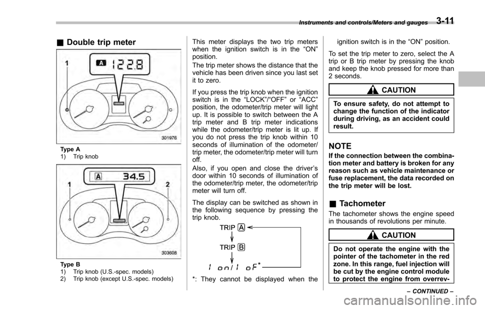
&Double trip meter
Type A
1) Trip knob
Type B
1) Trip knob (U.S.-spec. models)
2) Trip knob (except U.S.-spec. models)
This meter displays the two trip meters
when the ignition switch is in the “ON”
position.
The trip meter shows the distance that the
vehicle has been driven since you last set
it to zero.
If you press the trip knob when the ignition
switch is in the “LOCK”/ “OFF”or “ACC ”
position, the odometer/trip meter will light
up. It is possible to switch between the A
trip meter and B trip meter indications
while the odometer/trip meter is lit up. If
you do not press the trip knob within 10
seconds of illumination of the odometer/
trip meter, the odometer/trip meter will turn
off.
Also, if you open and close the driver ’s
door within 10 seconds of illumination of
the odometer/trip meter, the odometer/trip
meter will turn off.
The display can be switched as shown in
the following sequence by pressing the
trip knob.
*: They cannot be displayed when the ignition switch is in the
“ON ”position.
To set the trip meter to zero, select the A
trip or B trip meter by pressing the knob
and keep the knob pressed for more than
2 seconds.
CAUTION
To ensure safety, do not attempt to
change the function of the indicator
during driving, as an accident could
result.
NOTE
If the connection between the combina-
tion meter and battery is broken for any
reason such as vehicle maintenance or
fuse replacement, the data recorded on
the trip meter will be lost.
& Tachometer
The tachometer shows the engine speed
in thousands of revolutions per minute.
CAUTION
Do not operate the engine with the
pointer of the tachometer in the red
zone. In this range, fuel injection will
be cut by the engine control module
to protect the engine from overrev-
Instruments and controls/Meters and gauges
–CONTINUED –3-11
Page 158 of 594

efficiency.
NOTE
.The ECO gauge shows only an
approximate indication of fuel effi-
ciency.
. After resetting the trip meter, the
average rate of fuel consumption is not
shown until driving 0.6 mile (1 km).
Before that time, the ECO gauge does
not operate.
Warning and indicator lights
& Initial illumination for system
check
Several of the warning and indicator lights
illuminate when the ignition switch is
initially turned to the “ON ”position. This
permits checking the operation of the
bulbs.
Apply the parking brake and turn the
ignition switch to the “ON”position. For
the system check, the following lights
illuminate and then turn off after several
seconds or after the engine has started.
: Seatbelt warning light (The seatbelt warning light turns off
only when the driver fastens the
seatbelt.)
: Front passenger ’s seatbelt warning
light
(The seatbelt warning light turns off
only when the front seat passenger
fastens the seatbelt.)
: SRS airbag system warning light
ON /
: Front passenger ’s frontal airbag
ON indicator light
/: Front passenger ’s frontal airbag
OFF indicator light
: CHECK ENGINE warning light/Mal- function indicator light
: Coolant temperature low indicator light/Coolant temperature high warn-
ing light
: Charge warning light
: Oil pressure warning light
: Engine low oil level warning light
: Windshield washer fluid warning light
: AT OIL TEMP warning light(CVT models)
: Low tire pressure warning light(U.S.- spec. models)
/: ABS warning light
/: Brake system warning light
: Low fuel warning light
: Hill start assist warning light/Hill startassist OFF indicator light
: Door open warning light
: AWD warning light (CVT models)
: Power steering warning light
: Vehicle Dynamics Control warning light/Vehicle Dynamics Control opera-
tion indicator light
Instruments and controls/Warning and indicator lights
–CONTINUED –3-13
Page 162 of 594

NOTE
This light also illuminates when the fuel
filler cap is not tightened until it clicks.
If you have recently refueled your vehicle,
the cause of the CHECK ENGINE warning
light/malfunction indicator light illuminating
could be a loose or missing fuel filler cap.
Remove the cap and retighten it until it
clicks. Make sure nothing is interfering
with the sealing of the cap. Tightening the
cap will not make the CHECK ENGINE
warning light turn off immediately. It may
take several driving trips. If the light does
not turn off, take your vehicle to your
authorized SUBARU dealer immediately.
!If the light is blinking
If the light is blinking while driving, an
engine misfire condition has been de-
tected which may damage the emission
control system.
To prevent serious damage to the emis-
sion control system, you should do the
following.
. Reduce vehicle speed.
. Avoid hard acceleration.
. Avoid steep uphill grades.
. Reduce the amount of cargo, if possi-
ble.
. If towing a trailer, stop doing so as soon
as possible (trailer towing permitted with
Crosstrek models only). The CHECK ENGINE warning light may
stop blinking and illuminate steadily after
several driving trips. You should have your
vehicle checked by an authorized
SUBARU dealer immediately.
&Coolant temperature
low indicator light/Cool-
ant temperature high
warning light
CAUTION
.
After turning the ignition switch
to the “ON ”position, if this
indicator light/warning light be-
haves in any of the following
ways, the electrical system may
be malfunctioning. Contact your
SUBARU dealer immediately for
an inspection.
– It remains blinking in RED.
– It remains illuminated in RED
for more than 2 seconds.
– It remains blinking in RED and
BLUE alternately.
. While driving, if this indicator
light/warning light behaves in
any of the following ways, take
the specified appropriate mea-
sure listed below. –
Blinking or illuminated in
RED:
Safely stop the vehicle as
soon as possible, and refer
to the emergency steps to
take in the case of engine
overheating. After that, have
the system checked by your
nearest SUBARU dealer. Refer
to “Engine overheating ”F9-
13.
– Blinking in RED and BLUE
alternately:
The electrical system may be
malfunctioning. Contact your
SUBARU dealer for an inspec-
tion.
This coolant temperature low indicator
light/coolant temperature high warning
light has the following three functions.
. Illumination in BLUEindicates insuffi-
cient warming up of the engine
. Blinking in REDindicates that the
engine is close to overheating
. Illumination in REDindicates overheat-
ing condition of the engine
For a system check, this indicator light/
warning light illuminates in REDfor
approximately 2 seconds when the igni-
tion switch is turned to the “ON”position.
Instruments and controls/Warning and indicator lights
–CONTINUED –3-17
Page 163 of 594

Instruments and controls/Warning and indicator lights
After that, this indicator light/warning light
changes toBLUEand maintains illumina-
tion in BLUE. This BLUEilluminated light
turns off when the engine is warmed up
sufficiently.
If the engine coolant temperature in-
creases over the specified range, the
indicator light/warning light blinks in
RED . At this time, the engine is close to
overheating.
If the engine coolant temperature in-
creases further, the indicator light/warning
light illuminates in REDcontinuously. At
this time, the engine may be overheating.
When the indicator light/warning light
blinks in REDor illuminates in RED, safely
stop the vehicle as soon as possible, and
refer to the emergency steps to take in the
case of engine overheating. Refer to
“Engine overheating ”F 9-13. After that,
have the system checked by your nearest
SUBARU dealer.
Also, if the indicator light/warning light
often blinks in RED, the electrical system
may be malfunctioning. Contact your
SUBARU dealer for an inspection.
NOTE
If the engine is restarted after a certain
driving condition, this indicator light/ warning light may illuminate in RED.
However, this is not a malfunction if the
indicator light/warning light turns off
after a short time.
&Charge warning light
If this light illuminates when the engine is
running, it may indicate that the charging
system is not working properly.
If the light illuminates while driving or does
not turn off after the engine starts, stop the
engine at the first safe opportunity and
check the alternator belt. If the belt is
loose, broken or if the belt is in good
condition but the light remains illuminated,
contact your nearest SUBARU dealer
immediately.
&Oil pressure warning
light
If this light illuminates when the engine is
running, it may indicate that the engine oil
pressure is low and the lubricating system
is not working properly.
If the light illuminates while driving or does
not turn off after the engine starts, stop the
engine at the first safe opportunity and
check the engine oil level. If the oil level is
low, add oil immediately. If the engine oil is
at the proper level but the light remainsilluminated, contact your nearest
SUBARU dealer immediately.
For details about checking the engine oil
level or adding the engine oil, refer to
“Engine oil
”F 11-8.
CAUTION
Do not operate the engine with the
oil pressure warning light illumi-
nated. This may cause serious en-
gine damage.
&Engine low oil level
warning light
This light illuminates when the engine oil
level decreases to the lower limit.
If the engine low oil level warning light
illuminates while driving, park the vehicle
in a safe and level location, and then
check the engine oil level. When the
engine oil level is not within the normal
range, refill with engine oil. Refer to
“Engine oil ”F 11-8.
If the warning light does not turn off after
refilling the engine oil, or the warning light
illuminates even though the engine oil
level is within the normal range, have the
vehicle checked by a SUBARU dealer.
3-18
Page 164 of 594

NOTE
.After replacing or adding the engine
oil, if the engine oil level is within the
normal range when restarting the en-
gine on a level surface, the warning
light will turn off.
. The warning light may illuminate
temporarily in the following conditions
because a low oil level may be detected
as a result of significant oil movement
in the engine.
–when the vehicle is considerably
inclined on an uphill or steep slope
– when the vehicle has continu-
ously accelerated and decelerated
– when the vehicle is continuously
turned
– when the vehicle is driven on a
road that alternates continuously
between uphill and downhill
&Windshield washer
fluid warning light
This light illuminates when the fluid level in
the windshield washer fluid tank de-
creases to the lower limit (approximately
1.1 US qt, 1.0 liter, 0.9 Imp qt).
&AT OIL TEMP warning
light (CVT models)
If this light illuminates when the engine is
running, it may indicate that the transmis-
sion fluid temperature is too hot.
If the light illuminates while driving, im-
mediately stop the vehicle in a safe place
and let the engine idle until the warning
light turns off.
! Transmission control system warn-
ing
If the “AT OIL TEMP ”warning light flashes
after the engine has started, it may
indicate that the transmission control
system is not working properly. Contact
your nearest SUBARU dealer for service
immediately.
&Low tire pressure
warning light (U.S.-spec.
models)
When the ignition switch is turned to the
“ON ”position, the low tire pressure warn-
ing light will illuminate for approximately 2
seconds to check that the tire pressure
monitoring system (TPMS) is functioning
properly. If there is no problem and all tires
are properly inflated, the light will turn off.
Each tire, including the spare (if provided), should be checked monthly when cold
and inflated to the inflation pressure
recommended by the vehicle manufac-
turer on the vehicle placard or tire inflation
pressure label. (If your vehicle has tires of
a different size than the size indicated on
the vehicle placard or tire inflation pres-
sure label, you should determine the
proper tire inflation pressure for those
tires.)
As an added safety feature, your vehicle
has been equipped with a tire pressure
monitoring system (TPMS) that illuminates
a low tire pressure telltale when one or
more of your tires is significantly under-
inflated. Accordingly, when the low tire
pressure telltale illuminates, you should
stop and check your tires as soon as
possible, and inflate them to the proper
pressure. Driving on a significantly under-
inflated tire causes the tire to overheat and
can lead to tire failure. Under-inflation also
reduces fuel efficiency and tire tread life,
and may affect the vehicle
’s handling and
stopping ability.
Please note that the TPMS is not a
substitute for proper tire maintenance,
and it is the driver ’s responsibility to
maintain correct tire pressure, even if
under-inflation has not reached the level
to trigger illumination of the TPMS low tire
pressure telltale.
Instruments and controls/Warning and indicator lights
–CONTINUED –3-19
Page 168 of 594
dealer.
! Hill start assist OFF indicator light
While the Hill start assist system is
deactivated, the Hill start assist OFF
indicator light illuminates continuously to
inform the driver that the Hill start assist
system is not operational.
&Door open warning
light
The warning light illuminates if any door,
the rear gate (5-door models) or trunk lid
(4-door models) is not fully closed. This
function is effective even if the ignition
switch is in the “LOCK”/ “OFF”or “ACC ”
position, or the key is removed from the
ignition switch.
Always make sure this light is not illumi-
nated before you start to drive.
&All-Wheel Drive warn-
ing light (CVT models)
This light blinks if the vehicle is driven with
tires of differing diameters fitted on the
wheels or with an excessively low air
pressure in any of the tires.
WARNING
If the AWD warning light flashes,
promptly park in a safe location then
check whether all four tires are the
same diameter and whether any of
the tires has a puncture or has lost
air pressure for some other reason.
Continuing to drive with the AWD
warning light flashing can lead to
powertrain damage.
&Power steering warn-
ing light
This warning light illuminates when the
ignition switch is turned to the “ON ”
position and turns off after the engine
has started. This indicates that the warn-
ing system is working properly.
While the engine is running, this warning
light illuminates when a malfunction has
been detected in the electric power steer-
ing system.
CAUTION
When the power steering warning
light is illuminated, there may be
more resistance when the steering
wheel is operated. Drive carefully to the nearest SUBARU dealer and
have the vehicle inspected immedi-
ately.
NOTE
If the steering wheel is operated in the
following ways, the power steering
control system may temporarily limit
the power assist in order to prevent the
system components, such as the con-
trol computer and drive motor, from
overheating.
.
The steering wheel is operated fre-
quently and turned sharply while the
vehicle is maneuvered at extremely low
speeds, such as while frequently turn-
ing the steering wheel during parallel
parking.
. The steering wheel remains in the
fully turned position for a long period
of time.
At this time, there will be more resis-
tance when steering. However this is
not a malfunction. Normal steering
force will be restored after the steering
wheel is not operated for a while and
the power steering control system has
an opportunity to cool down. However,
if the power steering is operated in a
non-standard way which causes power
assist limitation to occur too fre-
Instruments and controls/Warning and indicator lights
–CONTINUED –3-23