automatic transmission SUBARU IMPREZA 2016 5.G Owners Manual
[x] Cancel search | Manufacturer: SUBARU, Model Year: 2016, Model line: IMPREZA, Model: SUBARU IMPREZA 2016 5.GPages: 594, PDF Size: 5.36 MB
Page 8 of 594

&Abbreviation list
You may find several abbreviations in this
manual. The meanings of the abbrevia-
tions are shown in the following list.
Abbreviation Meaning
A/C Air conditioner
ALR/ELR Automatic locking retractor/
Emergency locking retractor
ABS Anti-lock brake system
AKI Anti knock index
ALR Automatic locking retractor
AWD All-wheel drive
BSD/RCTA Blind Spot Detection/Rear
Cross Traffic Alert
CVT Continuously variable trans-
mission
DRL Daytime running light
EBD Electronic brake force distri-
bution
ELR Emergency locking retractor
GAW Gross axle weight
GAWR Gross axle weight rating
GPS Global positioning system
GVW Gross vehicle weight
GVWR Gross vehicle weight rating
HID High intensity discharge Abbreviation
Meaning
INT Intermittent
LATCH Lower anchors and tethers for
children
LED Light emitting diode
MIL Malfunction indicator light
MMT Methylcyclopentadienyl man-
ganese tricarbonyl
MT Manual transmission
OBD On-board diagnostics
RON Research octane number
SRF Steering responsive fog lights
system
SRS Supplemental restraint sys-
tem
TIN Tire identification number
TPMS Tire pressure monitoring sys-
tem
Vehicle symbols
There are some of the symbols you may
see on your vehicle.
For warning and indicator lights, refer to
“
Warning and indicator lights ”F 22.
Mark Name
WARNING
CAUTION
Read these instructions care-
fully
Wear eye protection
Battery fluid contains sulfuric
acid
Keep children away
Keep flames away
Prevent explosions
3
Page 176 of 594
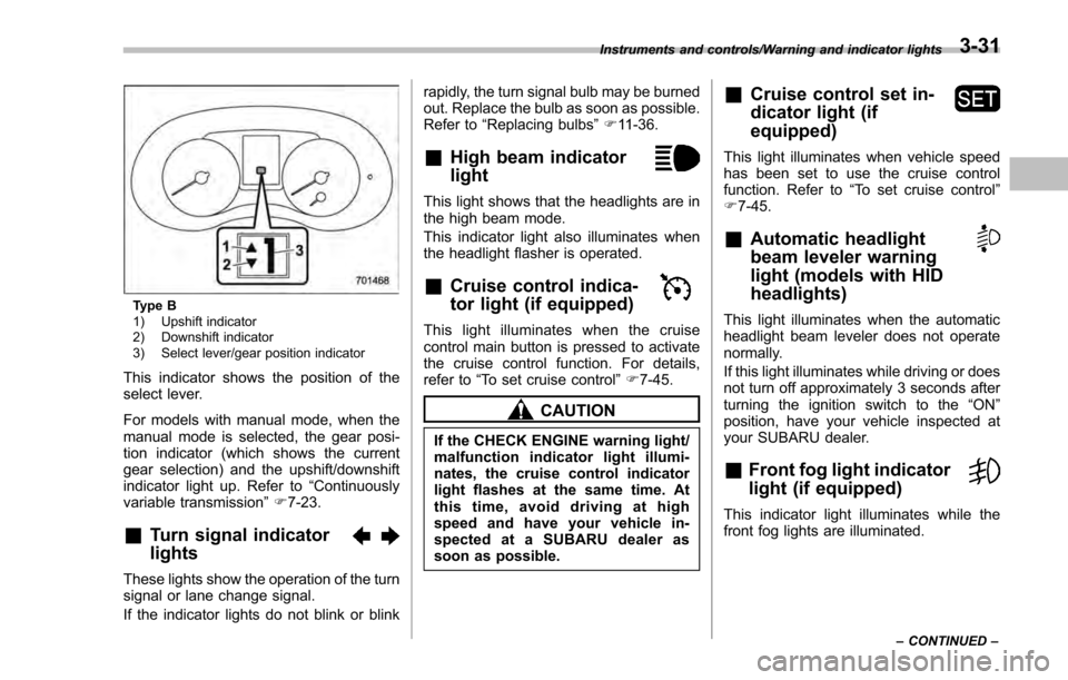
Type B
1) Upshift indicator
2) Downshift indicator
3) Select lever/gear position indicator
This indicator shows the position of the
select lever.
For models with manual mode, when the
manual mode is selected, the gear posi-
tion indicator (which shows the current
gear selection) and the upshift/downshift
indicator light up. Refer to“Continuously
variable transmission ”F 7-23.
&Turn signal indicator
lights
These lights show the operation of the turn
signal or lane change signal.
If the indicator lights do not blink or blink rapidly, the turn signal bulb may be burned
out. Replace the bulb as soon as possible.
Refer to
“Replacing bulbs ”F 11-36.
&High beam indicator
light
This light shows that the headlights are in
the high beam mode.
This indicator light also illuminates when
the headlight flasher is operated.
&Cruise control indica-
tor light (if equipped)
This light illuminates when the cruise
control main button is pressed to activate
the cruise control function. For details,
refer to “To set cruise control” F7-45.
CAUTION
If the CHECK ENGINE warning light/
malfunction indicator light illumi-
nates, the cruise control indicator
light flashes at the same time. At
this time, avoid driving at high
speed and have your vehicle in-
spected at a SUBARU dealer as
soon as possible.
&Cruise control set in-
dicator light (if
equipped)
This light illuminates when vehicle speed
has been set to use the cruise control
function. Refer to “To set cruise control ”
F 7-45.
&Automatic headlight
beam leveler warning
light (models with HID
headlights)
This light illuminates when the automatic
headlight beam leveler does not operate
normally.
If this light illuminates while driving or does
not turn off approximately 3 seconds after
turning the ignition switch to the “ON”
position, have your vehicle inspected at
your SUBARU dealer.
&Front fog light indicator
light (if equipped)
This indicator light illuminates while the
front fog lights are illuminated.
Instruments and controls/Warning and indicator lights
–CONTINUED –3-31
Page 245 of 594
Instruments and controls/Mirrors
fluid sprays until you release the knob.
To wash the rear window when the rear
wiper is not in use, turn the knob switch
downward to the“
”position. The washer
fluid sprays and the wiper operates until
you release the knob.
NOTE
When the amount of washer fluid is
getting low, the rear washer will run out
of fluid before the windshield washer.
This means that the amount of washer
fluid is low, and it should be added
immediately.
Mirrors
Always check that the inside and outside
mirrors are properly adjusted before you
start driving.
& Inside mirror
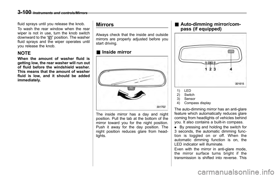
The inside mirror has a day and night
position. Pull the tab at the bottom of the
mirror toward you for the night position.
Push it away for the day position. The
night position reduces glare from head-
lights.
&Auto-dimming mirror/com-
pass (if equipped)
1) LED
2) Switch
3) Sensor
4) Compass display
The auto-dimming mirror has an anti-glare
feature which automatically reduces glare
coming from headlights of vehicles behind
you. It also contains a built-in compass.
. By pressing and holding the switch for
3 seconds, the automatic dimming func-
tion is toggled on or off. When the
automatic dimming function is on, the
LED indicator will illuminate.
Even with the mirror in anti-glare mode,
the mirror surface turns bright if the
transmission is shifted into reverse. This
3-100
Page 247 of 594
Instruments and controls/Mirrors
&Auto-dimming mirror/com-
pass with HomeLink
®(if
equipped)
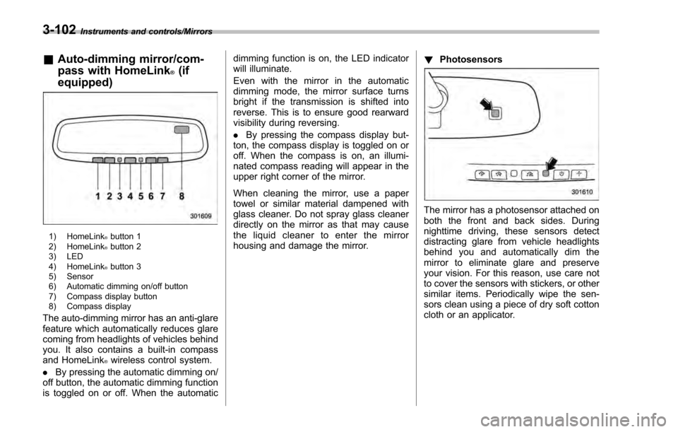
1) HomeLink®button 1
2) HomeLink®button 2
3) LED
4) HomeLink
®button 3
5) Sensor
6) Automatic dimming on/off button
7) Compass display button
8) Compass display
The auto-dimming mirror has an anti-glare
feature which automatically reduces glare
coming from headlights of vehicles behind
you. It also contains a built-in compass
and HomeLink
®wireless control system.
. By pressing the automatic dimming on/
off button, the automatic dimming function
is toggled on or off. When the automatic dimming function is on, the LED indicator
will illuminate.
Even with the mirror in the automatic
dimming mode, the mirror surface turns
bright if the transmission is shifted into
reverse. This is to ensure good rearward
visibility during reversing.
.
By pressing the compass display but-
ton, the compass display is toggled on or
off. When the compass is on, an illumi-
nated compass reading will appear in the
upper right corner of the mirror.
When cleaning the mirror, use a paper
towel or similar material dampened with
glass cleaner. Do not spray glass cleaner
directly on the mirror as that may cause
the liquid cleaner to enter the mirror
housing and damage the mirror. !
Photosensors
The mirror has a photosensor attached on
both the front and back sides. During
nighttime driving, these sensors detect
distracting glare from vehicle headlights
behind you and automatically dim the
mirror to eliminate glare and preserve
your vision. For this reason, use care not
to cover the sensors with stickers, or other
similar items. Periodically wipe the sen-
sors clean using a piece of dry soft cotton
cloth or an applicator.
3-102
Page 409 of 594
Starting and operating/Continuously variable transmission
mission.
. When parking the vehicle, first
securely apply the parking brake
and then place the select lever in
the “P”position. Do not park for
a long time with the select lever
in any other position as doing so
could result in a dead battery.
& Continuously variable trans-
mission features
The continuously variable transmission is
electronically controlled and provides an
infinite number of forward speeds and 1
reverse speed. For some models, it also
has a manual mode or an “L”position.
NOTE
. When the engine coolant tempera-
ture is still low, the transmission will
upshift or downshift at higher engine
speeds than when the coolant tempera-
ture is sufficiently high in order to
shorten the warm-up time and improve
driveability. The gearshift timing will
automatically shift to the normal timing
after the engine has warmed up.
. Immediately after transmission fluid
is replaced, you may feel that the
transmission operation is somewhat
unusual. This results from invalidation of data which the on-board computer
has collected and stored in memory to
allow the transmission to shift at the
most appropriate times for the current
condition of your vehicle. Optimized
shifting will be restored as the vehicle
continues to be driven for a while.
.
When driving a CVT model under
continuous heavy load conditions such
as when towing a camper or climbing a
long, steep hill, the engine speed or the
vehicle speed may automatically be
reduced. This is not a malfunction. This
phenomenon results from the engine
control function maintaining the cool-
ing performance of the vehicle. The
engine and vehicle speed will return to
a normal speed when the engine is able
to maintain the optimum cooling per-
formance after the heavy load de-
creases. Driving under a heavy load
must be performed with extreme care.
Do not try to pass a vehicle in front
when driving on an uphill slope while
towing. .
The continuously variable transmis-
sion is a chain type system that
provides superior transmission effi-
ciency for maximum fuel economy. At
times, depending on varying driving
conditions, a chain operating sound
may be heard that is characteristic of
this type of system.
& Select lever
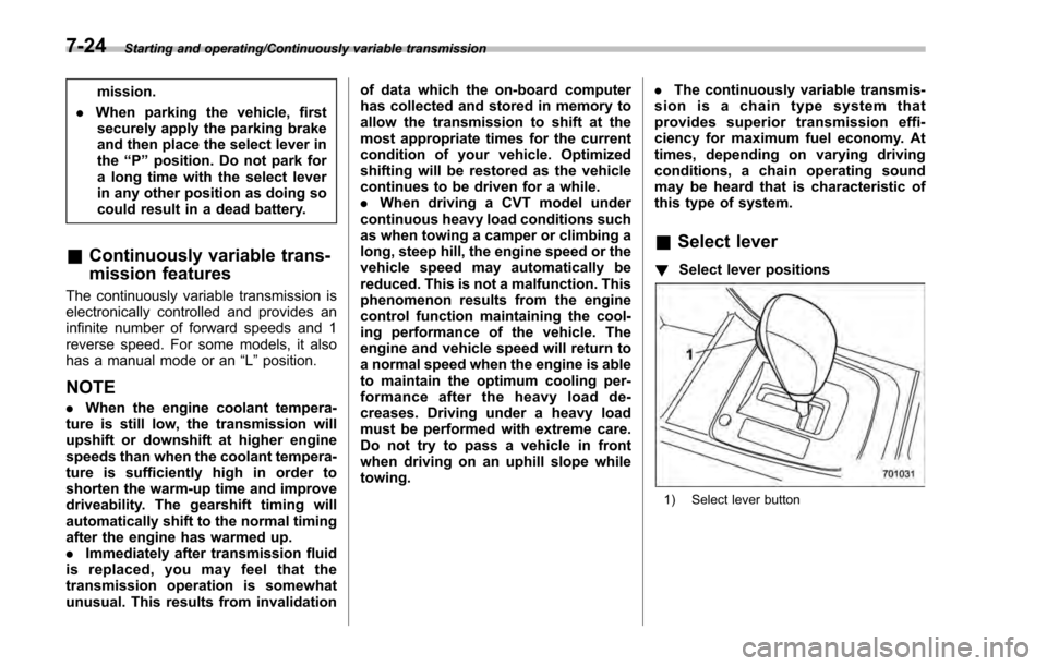
! Select lever positions
1) Select lever button
7-24
Page 411 of 594
Starting and operating/Continuously variable transmission
NOTE
If the select lever is in the“N”position
when you stop the engine for parking,
you may not subsequently be able to
move it to the “R”and “P”positions. If
this happens, turn the ignition switch to
the “ON ”position. You will then be able
to move the select lever to the “P”
position.
! D (Drive)
This position is for normal driving. The
transmission shifts automatically and con-
tinuously into a suitable gear according to
the vehicle speed and the acceleration
you require. Also, while driving up and
down a hill, the transmission assists and
controls the driving performance and
engine braking while corresponding to
the road grade.
When more acceleration is required in “D”
position, depress the accelerator pedal
fully to the floor and hold that position. The
transmission will automatically downshift.
In this case, the transmission will operate
like a conventional automatic transmis-
sion. When you release the pedal, the
transmission will return to the original gear
position.
For models with manual mode, if one of
the shift paddles behind the steering wheel is operated while driving in the
“D”
position, the transmission will temporarily
switch to the manual mode. In this mode,
you can shift into any gear position using
the shift paddles. For details about the
manual mode, refer to “Selection of
manual mode” F7-26. Once the vehicle
speed stabilizes, the transmission will
switch from the manual mode back to
the “D”position for normal driving.
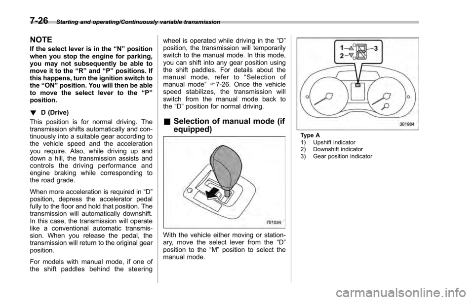
& Selection of manual mode (if
equipped)
With the vehicle either moving or station-
ary, move the select lever from the “D”
position to the “M”position to select the
manual mode.
Type A
1) Upshift indicator
2) Downshift indicator
3) Gear position indicator
7-26
Page 413 of 594
Starting and operating/Continuously variable transmission
sion.
.The transmission automatically se-
lects 1st gear when the vehicle stops
moving.
. If the temperature of the transmis-
sion fluid becomes too high, the “AT
OIL TEMP ”warning light on the combi-
nation meter will illuminate. Immedi-
ately stop the vehicle in a safe location
and let the engine idle until the warning
light turns off.
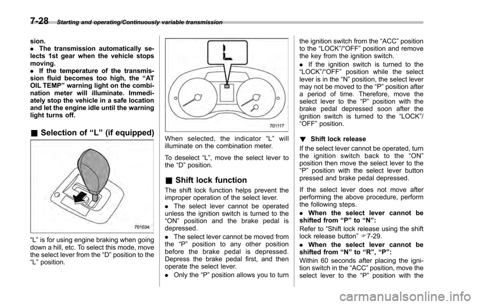
& Selection of “L ” (if equipped)
“L ”is for using engine braking when going
down a hill, etc. To select this mode, move
the select lever from the “D”position to the
“L ”position.
When selected, the indicator “L ” will
illuminate on the combination meter.
To deselect “L”, move the select lever to
the “D ”position.
& Shift lock function
The shift lock function helps prevent the
improper operation of the select lever.
. The select lever cannot be operated
unless the ignition switch is turned to the
“ ON ”position and the brake pedal is
depressed.
. The select lever cannot be moved from
the “P ” position to any other position
before the brake pedal is depressed.
Depress the brake pedal first, and then
operate the select lever.
. Only the “P”position allows you to turn the ignition switch from the
“ACC ”position
to the “LOCK”/ “OFF”position and remove
the key from the ignition switch.
. If the ignition switch is turned to the
“LOCK ”/“OFF ”position while the select
lever is in the “N”position, the select lever
may not be moved to the “P ”position after
a period of time. Therefore, move the
select lever to the “P ” position with the
brake pedal depressed soon after the
ignition switch is turned to the “LOCK”/
“OFF ”position.
! Shift lock release
If the select lever cannot be operated, turn
the ignition switch back to the “ON ”
position then move the select lever to the
“P ”position with the select lever button
pressed and brake pedal depressed.
If the select lever does not move after
performing the above procedure, perform
the following steps.
. When the select lever cannot be
shifted from “P”to “N ”:
Refer to “Shift lock release using the shift
lock release button ”F 7-29.
. When
the
select lever cannot be
shifted from “N”to “R”,“P ”:
Within 60 seconds after placing the igni-
tion switch in the “ACC”position, move the
select lever to the “P”position with the
7-28
Page 469 of 594

Driving tips/Trailer towing (Crosstrek models)
!Driving on grades
. Before going down a steep hill, slow
down and shift into lower gear (if neces-
sary, use 1st gear) in order to utilize the
engine braking effect and prevent over-
heating of your vehicle’ s brakes. Do not
make sudden downshifts.
. When driving uphill in hot weather, the
air conditioner may turn off automatically
to protect the engine from overheating.
. When driving uphill in hot weather, pay
attention to the following indicators be-
cause the engine and transmission are
relatively prone to overheating.
: Coolant temperature high warning light
: AT OIL TEMP warning light (CVT models)
If the coolant temperature high warning
light and/or the AT OIL TEMP warning light
illuminates, immediately turn off the air
conditioner and stop the vehicle in the
nearest safe location. For further instruc-
tions and additional information, refer to
the following sections. –“If you park your vehicle in case of
an emergency ”F 9-2
–“ Engine overheating ”F 9-13
–“ Coolant temperature low indicator
light/Coolant temperature high warn-
ing light ”F 3-17 –“
AT OIL TEMP warning light (CVT
models) ”F 3-19
. For CVT models, avoid using the
accelerator pedal to stay stationary on
an uphill slope instead of using the
parking brake or foot brake. That may
cause the transmission fluid to overheat.
! Parking on a grade
Always block the wheels under both
vehicle and trailer when parking. Apply
the parking brake firmly. You should not
park on a hill or slope. If parking on a hill or
slope cannot be avoided, you should take
the following steps:
1. Apply the brakes and hold the pedal
down.
2. Have someone place wheel blocks
under both the vehicle and trailer wheels.
3. When the wheel blocks are in place,
release the regular brakes slowly until the
blocks absorb the load.
4. Apply the regular brakes and then
apply the parking brake; slowly release
the regular brakes.
5. Shift into 1st or reverse gear (MT
models) or “P ” position (CVT models)
and shut off the engine.
8-26
Page 509 of 594

Maintenance and service/Spark plugs
Spark plugs
It may be difficult to replace the spark
plugs. It is recommended that you have
the spark plugs replaced by your
SUBARU dealer.
The spark plugs should be replaced
according to the maintenance schedule
in the“Warranty and Maintenance Book-
let ”.
CAUTION
Make sure the cables are replaced in
the correct order.
& Recommended spark plugs
For the recommended spark plugs, refer
to“Electrical system ”F 12-7.
Drive belts
It is unnecessary to check the deflection of
the drive belt periodically because your
engine is equipped with an automatic belt
tension adjuster. However, replacement of
the belt should be done according to the
maintenance schedule in the “Warranty
and Maintenance Booklet ”. Consult your
SUBARU dealer for replacement.
If the drive belt is loose, cracked or worn,
contact your SUBARU dealer.
Manual transmission oil
It is not necessary to check the transmis-
sion oil level. Check that there are no
cracks, damage or leakage. However, the
oil inspection should be performed ac-
cording to the maintenance schedule in
the “Warranty and Maintenance Booklet ”.
Consult your SUBARU dealer for details.
& Recommended grade and
viscosity
Each oil manufacturer has its own base
oils and additives. Never use different
brands together. For details, refer to
“Manual transmission, front differential
and rear differential gear oil ”F 12-6.
11-14
Page 581 of 594

14-4Index
CleaningAluminum wheels ................................................... 10-3
Interior .................................................................. 10-5
Ventilation grille ..................................................... 4-11
Climate control system ................................................. 4-3
Automatic ................................................................ 4-7
Manual ................................................................... 4-8
Clock ................................................................ 3-37, 3-52
Clutch
Fluid .................................................................... 11-17
Pedal .................................................................. 11-19
Coat hook ................................................................. 6-11
Compass ....................................................... 3- 100, 3-102
Continuously variable transmission (CVT) ..................... 7-23
Fluid ............................................................ 11-15, 12-7
Oil temperature warning light (AT OIL TEMP) ............ 3-19
Coolant ............................................................ 11-11, 12-7
Temperature high warning light ................................ 3-17
Temperature low indicator light. ................................ 3-17
Cooling system ......................................................... 11-10
Corrosion protection ................................................... 10-4
Cruise control ............................................................ 7-45
Indicator light ......................................................... 3-31
Set indicator light ................................................... 3-31
Cup holder .................................................................. 6-7
D
Daytime running light system ....................................... 3-92
Defogger ................................................................. 3-108
Defrosting ................................................................. 4-11
Deicer .................................................................... 3-108 Differential gear oil
Front ........................................................... 11-15, 12-6
Rear ........................................................... 11-15, 12-6
Dimensions ................................................................ 12-2
Disarming the alarm system ......................................... 2-32
Disc brake pad wear warning indicators ........................ 7-32
Dome light ......................................................... 6-2, 11-42
Door Locks ..................................................................... 2-5
Open warning light. ................................................. 3-23
Drive belts ............................................................... 11-14
Driving AWD vehicles ......................................................... 8-4
Car phone/cell phone .................................................. 7
Drinking. .................................................................... 6
Drugs ........................................................................\
6
Foreign countries ..................................................... 8-4
Off road .................................................................. 8-6
Pets ........................................................................\
.. 7
Snowy and icy roads ............................................... 8-9
Tips ................................................. 7-23, 7-29, 8-2, 8-4
Tired or sleepy ........................................................... 6
Winter .................................................................... 8-8
E
ECO gauge ....................................................... 3-12, 3-49
Electrical system........................................................
12-7
Electronic Brake Force Distribution (EBD) system ........... 7-33
Warning ................................................................ 3-22
Emergency Locking Retractor (ELR) ............................. 1-12