wheel nut SUBARU IMPREZA 2016 5.G Owners Manual
[x] Cancel search | Manufacturer: SUBARU, Model Year: 2016, Model line: IMPREZA, Model: SUBARU IMPREZA 2016 5.GPages: 594, PDF Size: 5.36 MB
Page 165 of 594
Instruments and controls/Warning and indicator lights
Your vehicle has also been equipped with
a TPMS malfunction indicator to indicate
when the system is not operating properly.
The TPMS malfunction indicator is com-
bined with the low tire pressure telltale.
When the system detects a malfunction,
the telltale will flash for approximately one
minute and then remain continuously
illuminated. This sequence will continue
upon subsequent vehicle start-ups as long
as the malfunction exists. When the
malfunction indicator is illuminated, the
system may not be able to detect or signal
low tire pressure as intended. TPMS
malfunctions may occur for a variety of
reasons, including the installation of re-
placement or alternate tires or wheels on
the vehicle that prevent the TPMS from
functioning properly. Always check the
TPMS malfunction telltale after replacing
one or more tires or wheels on your
vehicle to ensure that the replacement or
alternate tires and wheels allow the TPMS
to continue to function properly.
Should the warning light illuminate stea-
dily after blinking for approximately one
minute, have the system inspected by
your nearest SUBARU dealer as soon as
possible.
WARNING
If this light does not illuminatebriefly after the ignition switch is
turned ON or the light illuminates
steadily after blinking for approxi-
mately one minute, you should have
your Tire Pressure Monitoring Sys-
tem checked at a SUBARU dealer as
soon as possible.
If this light illuminates while driving,
never brake suddenly and keep
driving straight ahead while gradu-
ally reducing speed. Then slowly
pull off the road to a safe place.
Otherwise an accident involving
serious vehicle damage and serious
personal injury could occur.
If this light still illuminates while
driving after adjusting the tire pres-
sure, a tire may have significant
damage and a fast leak that causes
the tire to lose air rapidly. If you have
a flat tire, replace it with a spare tire
as soon as possible.
When a spare tire is mounted or a
wheel rim is replaced without the
original pressure sensor/transmitter
being transferred, the Low tire pres-
sure warning light will illuminate
steadily after blinking for approxi-
mately one minute. This indicates
the TPMS is unable to monitor all
four road wheels. Contact your
SUBARU dealer as soon as possiblefor tire and sensor replacement and/
or system resetting.
If the light illuminates steadily after
blinking for approximately one min-
ute, promptly contact a SUBARU
dealer to have the system inspected.
CAUTION
The tire pressure monitoring system
is NOT a substitute for manually
checking tire pressure. The tire
pressure should be checked peri-
odically (at least monthly) using a
tire gauge. After any change to tire
pressure(s), the tire pressure mon-
itoring system will not re-check tire
inflation pressures until the vehicle
is first driven more than 20 mph (32
km/h). After adjusting the tire pres-
sures, increase the vehicle speed to
at least 20 mph (32 km/h) to start the
TPMS re-checking of the tire infla-
tion pressures. If the tire pressures
are now above the severe low
pressure threshold, the low tire
pressure warning light should turn
off a few minutes later. Therefore, be
sure to install the specified size for
the front and rear tires.
3-20
Page 170 of 594
existence of a problem. The light
should turn off as soon as the engine
has warmed up.
.The indicator light illuminates when
the engine has developed a problem
and the CHECK ENGINE warning light/
malfunction indicator light is on.
The Vehicle Dynamics Control system is
probably malfunctioning under the follow-
ing condition. Have your vehicle checked
at a SUBARU dealer as soon as possible.
. The light does not turn off even after
the lapse of several minutes (the engine
has warmed up) after the engine has
started.
&Vehicle Dynamics
Control OFF indicator
light
The light illuminates when the Vehicle
Dynamics Control OFF switch is pressed
to deactivate the Vehicle Dynamics Con-
trol system.
The Vehicle Dynamics Control system is
probably malfunctioning under any of the
following conditions. Have your vehicle
checked at a SUBARU dealer immedi-
ately.
. The light does not illuminate when the
ignition switch is turned to the “ON ”
position. .
The light does not turn off even once
several seconds have elapsed after the
ignition switch has been turned to the
“ON ”position.
& Warning chimes and warning
indicator of the keyless ac-
cess with push-button start
system (if equipped)
Access key warning indicator (type A)
Access key warning indicator (type B)
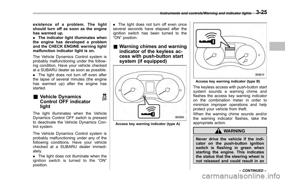
The keyless access with push-button start
system sounds a warning chime and
flashes the access key warning indicator
on the combination meter in order to
minimize improper operations and help
protect your vehicle from theft.
When the warning chime sounds and/or
the warning indicator flashes, take the
appropriate action.
WARNING
Never drive the vehicle if the indi-
cator on the push-button ignition
switch is flashing in green when
starting the engine. This indicates
the status that the steering wheel is
not released and could result in an
Instruments and controls/Warning and indicator lights
–CONTINUED –3-25
Page 255 of 594
Instruments and controls/Tilt/telescopic steering wheel
of the rear window. They may
damage the conductors printed
on the window.
NOTE
.Turn on the defogger and deicer
system if the wipers are frozen to the
windshield.
. If the windshield is covered with
snow, remove the snow so that the
windshield wiper deicer works effec-
tively.
. While the defogger and deicer sys-
tem is in the continuous operation
mode, if the vehicle speed remains at
9mph(15km/h)orlowerfor15
minutes, the windshield wiper deicer
automatically stops operating, though
the rear window defogger and outside
mirror defogger maintain continuous
operation in this condition.
. While the defogger and deicer sys-
tem is in the continuous operation
mode, if the battery voltage drops
below the permissible level, continu-
ous operation of the defogger and
deicer system is canceled and the
system stops operating.
Tilt/telescopic steering wheel
WARNING
. Do not adjust the steering wheel
tilt/telescopic position while driv-
ing. This may cause loss of
vehicle control and result in
personal injury.
. If the lever cannot be raised to
the fixed position, adjust the
steering wheel again. It is dan-
gerous to drive without locking
the steering wheel. This may
cause loss of vehicle control
and result in personal injury.
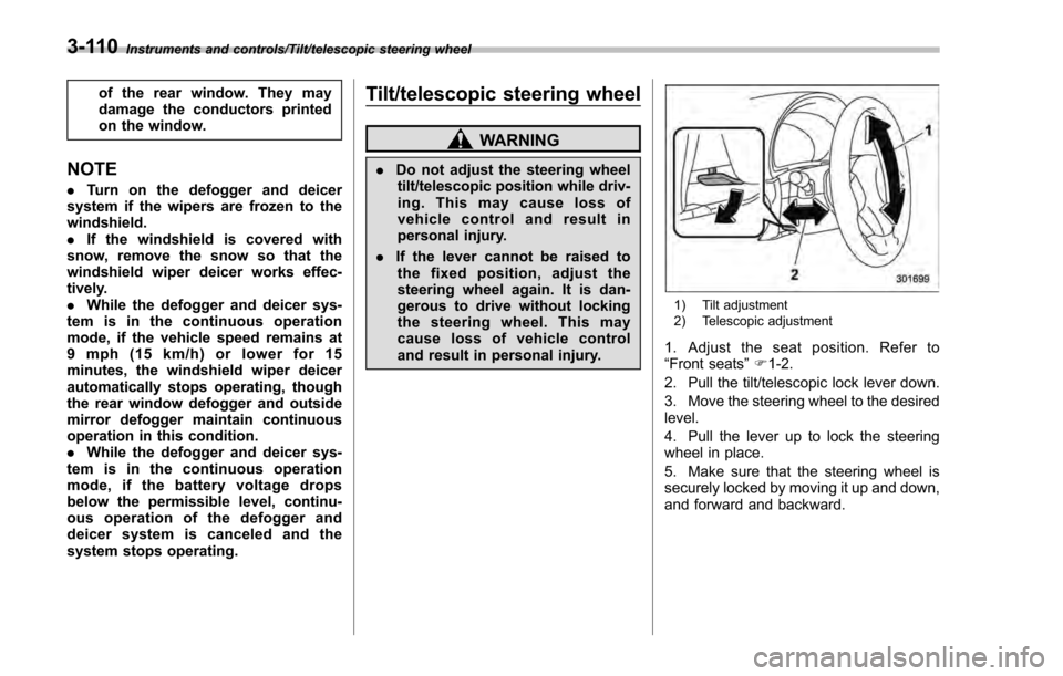
1) Tilt adjustment
2) Telescopic adjustment
1. Adjust the seat position. Refer to
“Front seats ”F 1-2.
2. Pull the tilt/telescopic lock lever down.
3. Move the steering wheel to the desired
level.
4. Pull the lever up to lock the steering
wheel in place.
5. Make sure that the steering wheel is
securely locked by moving it up and down,
and forward and backward.
3-110
Page 424 of 594
pressure threshold, the low tire
pressure warning light should
turn off a few minutes later.
If this light still illuminates while
driving after adjusting the tire
pressure, a tire may have signifi-
cant damage and a fast leak that
causes the tire to lose air rapidly.
If you have a flat tire, replace it
with a spare tire as soon as
possible.
. When a spare tire is mounted or a
wheel rim is replaced without the
original pressure sensor/trans-
mitter being transferred, the low
tire pressure warning light will
illuminate steadily after blinking
for approximately one minute.
This indicates the TPMS is un-
able to monitor all four road
wheels. Contact your SUBARU
dealer as soon as possible for
tire and sensor replacement and/
or system resetting.
. When a tire is repaired with liquid
sealant, the tire pressure warning
valve and transmitter may not
operate properly. If a liquid sea-
lant is used, contact your nearest
SUBARU dealer or other qualified
service shop as soon as possi-
ble. Make sure to replace the tire pressure warning valve and
transmitter when replacing the
tire. You may reuse the wheel if
there is no damage to it and if the
sealant residue is properly
cleaned off. Do not inject any tire
liquid or aerosol tire sealant into
the tires, as this may cause a
malfunction of the tire pressure
sensors. If the light illuminates
steadily after blinking for ap-
proximately one minute,
promptly contact a SUBARU
dealer to have the system in-
spected.
CAUTION
Do not place metal film or any metal
parts in the trunk. This may cause
poor reception of the signals from
the tire pressure sensors, and the
tire pressure monitoring system will
not function properly.
FCC ID: CWTWD1U781
NOTE
This device complies with part 15 of the
FCC Rules. Operation is subject to the
following two conditions: (1) This de-
vice may not cause harmful interfer- ence, and (2) this device must accept
any interference received, including
interference that may cause undesired
operation.
FCC CAUTION
Changes or modifications not ex-
pressly approved by the party respon-
sible for compliance could void the
user
’s authority to operate the equip-
ment.
Starting and operating/Tire pressure monitoring system (TPMS) (U.S. –spec. models)7-39
Page 462 of 594
manufacturer.
SUBARU assumes no responsibility for
injuries or vehicle damage that result from
trailer towing equipment, or from any
errors or omissions in the instructions
accompanying such equipment or for your
failure to follow the proper instructions.
Regularly check that the hitch mounting
bolts and nuts are tightened securely.
&Warranties and maintenance
SUBARU warranties do not apply to
vehicle damage or malfunction caused
by trailer towing. If you use your vehicle to
tow a trailer, more frequent maintenance
will be required due to the additional load.
(Refer to “Maintenance schedule under
severe driving conditions ”in the “Warranty
and Maintenance Booklet ”.)
Under no circumstances should a trailer
be towed with a new vehicle or a vehicle
with any new powertrain component (en-
gine, transmission, differential, wheel
bearings, etc.) for the first 1,000 miles
(1,600 km) of driving.
& Maximum load limits
WARNING
Never exceed the maximum load
limits explained in the following.
Exceeding the maximum load limits
could cause personal injury and/or
vehicle damage.
CAUTION
. Adequate size trailer brakes are
required when the trailer and its
cargo exceed 1,000 lbs (453 kg)
total weight.
. Before towing a trailer, check the
trailer total weight, GVW, GAWs
and tongue load. Make sure the
load and its distribution in your
vehicle and trailer are accepta-
ble. !
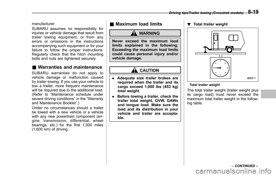
Total trailer weight
Total trailer weight
The total trailer weight (trailer weight plus
its cargo load) must never exceed the
maximum total trailer weight in the follow-
ing table.
Driving tips/Trailer towing (Crosstrek models)
–CONTINUED –8-19
Page 471 of 594
In case of emergency/If you park your vehicle in case of an emergency
If you park your vehicle in
case of an emergency
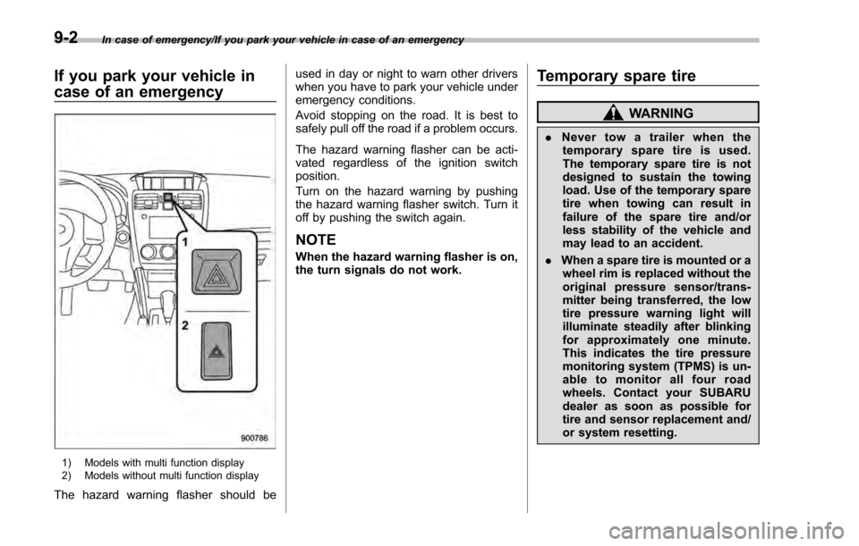
1) Models with multi function display
2) Models without multi function display
The hazard warning flasher should beused in day or night to warn other drivers
when you have to park your vehicle under
emergency conditions.
Avoid stopping on the road. It is best to
safely pull off the road if a problem occurs.
The hazard warning flasher can be acti-
vated regardless of the ignition switch
position.
Turn on the hazard warning by pushing
the hazard warning flasher switch. Turn it
off by pushing the switch again.
NOTE
When the hazard warning flasher is on,
the turn signals do not work.
Temporary spare tire
WARNING
.
Never tow a trailer when the
temporary spare tire is used.
The temporary spare tire is not
designed to sustain the towing
load. Use of the temporary spare
tire when towing can result in
failure of the spare tire and/or
less stability of the vehicle and
may lead to an accident.
. When a spare tire is mounted or a
wheel rim is replaced without the
original pressure sensor/trans-
mitter being transferred, the low
tire pressure warning light will
illuminate steadily after blinking
for approximately one minute.
This indicates the tire pressure
monitoring system (TPMS) is un-
able to monitor all four road
wheels. Contact your SUBARU
dealer as soon as possible for
tire and sensor replacement and/
or system resetting.
9-2
Page 472 of 594

CAUTION
Never use any temporary spare tire
other than the original. Using other
sizes may result in severe mechan-
ical damage to the drive train of your
vehicle.
The temporary spare tire is smaller and
lighter than a conventional tire and is
designed for emergency use only. Re-
move the temporary spare tire and re-
install the conventional tire as soon as
possible because the spare tire is de-
signed only for temporary use.
Check the inflation pressure of the tem-
porary spare tire periodically to keep the
tire ready for use. The correct pressure is
60 psi (420 kPa, 4.2 kg/cm
2).
When using the temporary spare tire, note
the following.
. Do not exceed 50 mph (80 km/h).
. Do not put a tire chain on the temporary
spare tire. Because of the smaller tire size,
a tire chain will not fit properly.
. Do not use two or more temporary
spare tires at the same time.
. Do not drive over obstacles. This tire
has a smaller diameter, so road clearance
is reduced.
1) Tread wear indicator bar
2) Indicator location mark
. When the wear indicator appears on
the tread, replace the tire.
. The temporary spare tire must be used
only on a rear wheel. If a front wheel tire
gets punctured, replace the wheel with a
rear wheel and install the temporary spare
tire in place of the removed rear wheel.
Maintenance tools
Your vehicle is equipped with the following
maintenance tools.
. Jack
. Jack handle
. Screwdriver
. Towing hook (eye bolt)
. Wheel nut wrench
In case of emergency/Maintenance tools
–CONTINUED –9-3
Page 473 of 594
In case of emergency/Maintenance tools
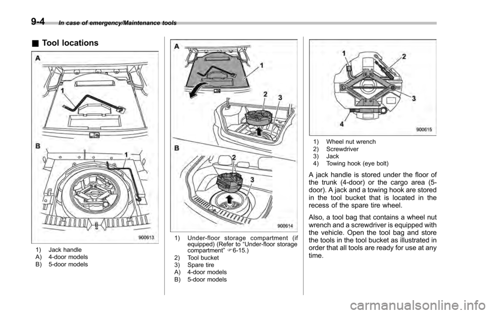
&Tool locations
1) Jack handle
A) 4-door models
B) 5-door models
1) Under-floor storage compartment (if
equipped) (Refer to “Under-floor storage
compartment ”F 6-15.)
2) Tool bucket
3) Spare tire
A) 4-door models
B) 5-door models
1) Wheel nut wrench
2) Screwdriver
3) Jack
4) Towing hook (eye bolt)
A jack handle is stored under the floor of
the trunk (4-door) or the cargo area (5-
door). A jack and a towing hook are stored
in the tool bucket that is located in the
recess of the spare tire wheel.
Also, a tool bag that contains a wheel nut
wrench and a screwdriver is equipped with
the vehicle. Open the tool bag and store
the tools in the tool bucket as illustrated in
order that all tools are ready for use at any
time.
9-4
Page 475 of 594
In case of emergency/Flat tires
Flat tires
If you have a flat tire while driving, never
brake suddenly; keep driving straight
ahead while gradually reducing speed.
Then slowly pull off the road to a safe
place.
&Changing a flat tire
WARNING
. Do not jack up the vehicle on an
incline or a loose road surface.
The jack can come out of the
jacking point or sink into the
ground and this can result in a
severe accident.
. Use only the jack provided with
your vehicle. The jack supplied
with the vehicle is designed only
for changing a tire. Never get
under the vehicle while support-
ing the vehicle with this jack.
. Always turn off the engine before
raising the flat tire off the ground
using the jack. Never swing or
push the vehicle supported with
the jack. The jack can come out
of the jacking point due to a jolt
and this can result in a severe accident.
1. Park on a hard, level surface, when-
ever possible, then stop the engine.
2. Apply the parking brake securely and
shift the shift lever in reverse (MT models)
or the select lever to the “P ” (Park)
position (CVT models).
3. Turn on the hazard warning flasher
and have everyone get out of the vehicle.
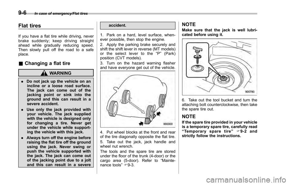
4. Put wheel blocks at the front and rear
of the tire diagonally opposite the flat tire.
5. Take out the jack, jack handle and
wheel nut wrench.
The tools and the spare tire are stored
under the floor of the trunk (4-door) or the
cargo area (5-door). Refer to “Mainte-
nance tools ”F 9-3.
NOTE
Make sure that the jack is well lubri-
cated before using it.
6. Take out the tool bucket and turn the
attaching bolt counterclockwise, then take
the spare tire out.
NOTE
If the spare tire provided in your vehicle
is a temporary spare tire, carefully read
“Temporary spare tire ”F9-2 and
strictly follow the instructions.
9-6
Page 476 of 594
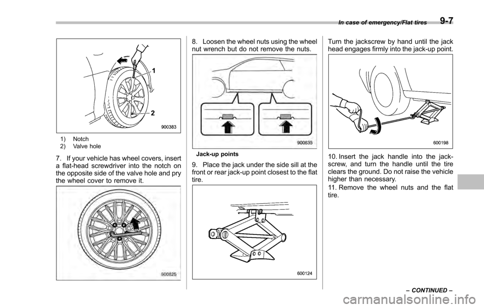
1) Notch
2) Valve hole
7. If your vehicle has wheel covers, insert
a flat-head screwdriver into the notch on
the opposite side of the valve hole and pry
the wheel cover to remove it.
8. Loosen the wheel nuts using the wheel
nut wrench but do not remove the nuts.
Jack-up points
9. Place the jack under the side sill at the
front or rear jack-up point closest to the flat
tire.
Turn the jackscrew by hand until the jack
head engages firmly into the jack-up point.
10. Insert the jack handle into the jack-
screw, and turn the handle until the tire
clears the ground. Do not raise the vehicle
higher than necessary.
11. Remove the wheel nuts and the flat
tire.
In case of emergency/Flat tires–CONTINUED –9-7