coolant SUBARU IMPREZA WRX 2006 2.G User Guide
[x] Cancel search | Manufacturer: SUBARU, Model Year: 2006, Model line: IMPREZA WRX, Model: SUBARU IMPREZA WRX 2006 2.GPages: 365, PDF Size: 7.09 MB
Page 286 of 365
Maintenance and service 11-7
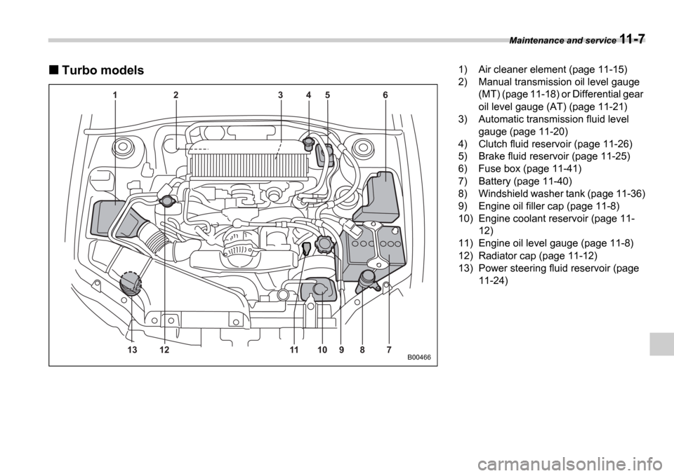
Turbo models
1 2 3 4 5 6
7
8
9
10
11
12
13
B00466
1) Air cleaner element (page 11-15)
2) Manual transmission oil level gauge
(MT) (page 11-18) or Differential gear
oil level gauge (AT) (page 11-21)
3) Automatic transmission fluid level gauge (page 11-20)
4) Clutch fluid reservoir (page 11-26)
5) Brake fluid reservoir (page 11-25)
6) Fuse box (page 11-41)
7) Battery (page 11-40)
8) Windshield washer tank (page 11-36)
9) Engine oil filler cap (page 11-8)
10) Engine coolant reservoir (page 11- 12)
11) Engine oil level gauge (page 11-8)
12) Radiator cap (page 11-12)
13) Power steering fluid reservoir (page
11-24)
Page 291 of 365
11-12 Maintenance and service
Cooling system
Cooling fan, hose and con-
nections
Your vehicle employs an electric cooling
fan which is thermostatically controlled to
operate when the engine coolant reaches
a specific temperature.
If the radiator cooling fan does not operate
even when the engine coolant tempera-
ture gauge exceeds the normal operating
range, the cooling fan circuit may be de-
fective. Check the fuse and replace it if
necessary. If the fuse is not blown, have
the cooling system checked by your
SUBARU dealer.
If frequent addition of coolant is neces-
sary, there may be a leak in the engine
cooling system. It is recommended that
the cooling system and connections be
checked for leaks, damage, or looseness.
Engine coolant
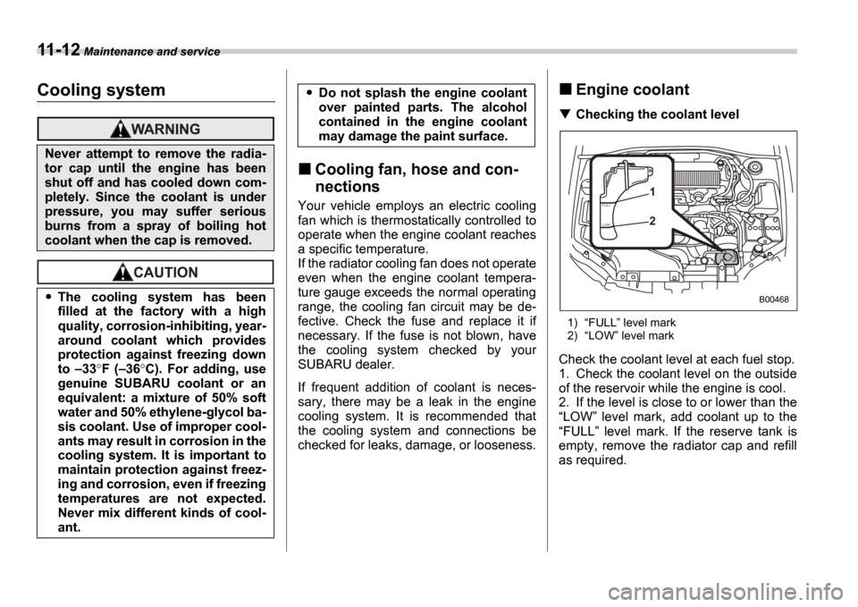
Checking the coolant level
1)FULL level mark
2) LOW level mark
Check the coolant level at each fuel stop.
1. Check the coolant level on the outside
of the reservoir while the engine is cool.
2. If the level is close to or lower than the LOW level mark, add coolant up to the
FULL level mark. If the reserve tank is
empty, remove the radiator cap and refill
as required.
Never attempt to remove the radia-
tor cap until the engine has been
shut off and has cooled down com-
pletely. Since the coolant is under
pressure, you may suffer serious
burns from a spray of boiling hot
coolant when the cap is removed.
The cooling system has been
filled at the factory with a high
quality, corrosion-inhibiting, year-
around coolant which provides
protection against freezing down
to 33 F ( 36 C). For adding, use
genuine SUBARU coolant or an
equivalent: a mixture of 50% soft
water and 50% ethylene-glycol ba-
sis coolant. Use of improper cool-
ants may result in corrosion in the
cooling system. It is important to
maintain protection against freez-
ing and corrosion, even if freezing
temperatures are not expected.
Never mix different kinds of cool-
ant.
Do not splash the engine coolant
over painted parts. The alcohol
contained in the engine coolant
may damage the paint surface.
F U L L
L OW1 2
B00468
Page 292 of 365
Maintenance and service 11-13
CONTINUED
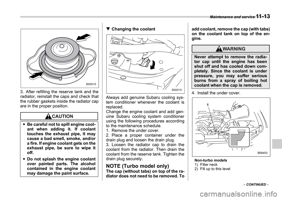
3. After refilling the reserve tank and the
radiator, reinstall the caps and check that
the rubber gaskets inside the radiator cap
are in the proper position.
Changing the coolant
Always add genuine Subaru cooling sys-
tem conditioner whenever the coolant is
replaced.
Change the engine coolant and add gen-
uine Subaru cooling system conditioner
using the following procedures according
to the maintenance schedule.
1. Remove the under cover.
2. Place a proper container under the
drain plug and loosen the drain plug.
3. Loosen the radiator cap to drain the
coolant from the radiator. Then drain the
coolant from the reserve tank. Tighten the
drain plug securely.
NOTE (Turbo model only)
The cap (without tabs) on top of the ra-
diator does not need to be removed. To add coolant, remove the cap (with tabs)
on the coolant tank on top of the en-
gine.
4. Install the under cover.
Non-turbo models
1) Filler neck
2) Fill up to this level
Be careful not to spill engine cool-
ant when adding it. If coolant
touches the exhaust pipe, it may
cause a bad smell, smoke, and/or
a fire. If engine coolant gets on the
exhaust pipe, be sure to wipe it
off.
Do not splash the engine coolant
over painted parts. The alcohol
contained in the engine coolant
may damage the paint surface.
B00018
B00019
Never attempt to remove the radia-
tor cap until the engine has been
shut off and has cooled down com-
pletely. Since the coolant is under
pressure, you may suffer serious
burns from a spray of boiling hot
coolant when the cap is removed.
1
2
B00453
Page 293 of 365
11-14 Maintenance and service
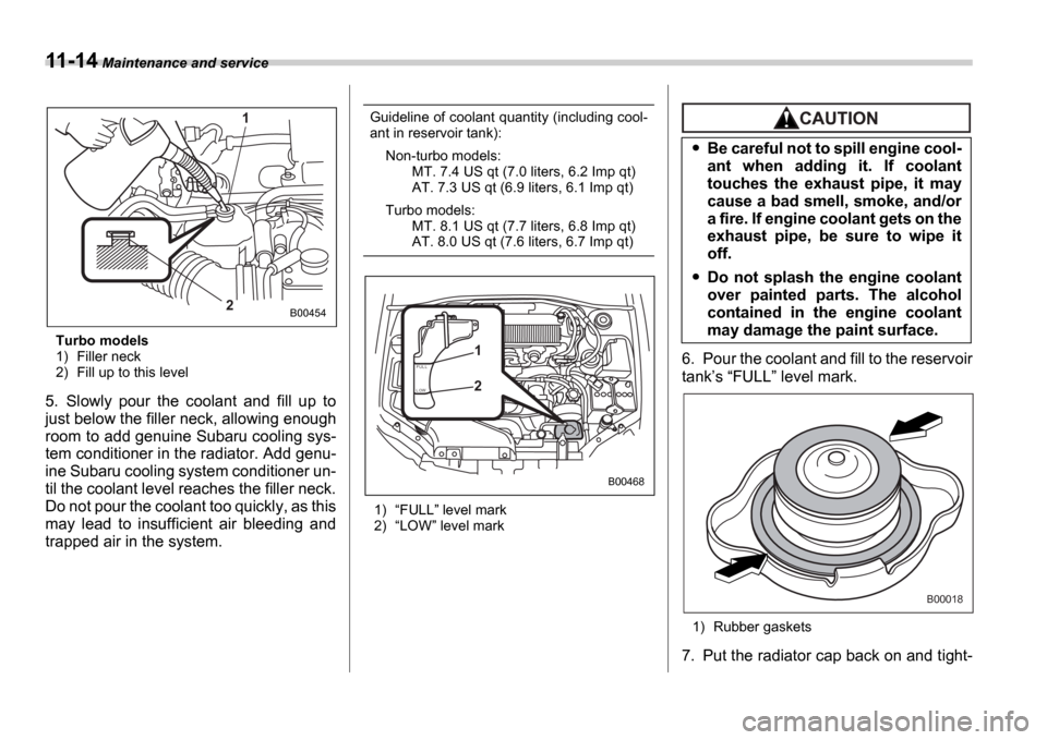
Turbo models
1) Filler neck
2) Fill up to this level
5. Slowly pour the coolant and fill up to
just below the filler neck, allowing enough
room to add genuine Subaru cooling sys-
tem conditioner in the radiator. Add genu-
ine Subaru cooling system conditioner un-
til the coolant level reaches the filler neck.
Do not pour the coolant too quickly, as this
may lead to insufficient air bleeding and
trapped air in the system.
Guideline of coolant quantity (including cool-
ant in reservoir tank):
Non-turbo models: MT. 7.4 US qt (7.0 liters, 6.2 Imp qt)
AT. 7.3 US qt (6.9 liters, 6.1 Imp qt)
Turbo models: MT. 8.1 US qt (7.7 liters, 6.8 Imp qt)
AT. 8.0 US qt (7.6 liters, 6.7 Imp qt)
1) FULL level mark
2) LOW level mark
6. Pour the coolant and fill to the reservoir
tank s FULL level mark.
1) Rubber gaskets
7. Put the radiator cap back on and tight-
1
2
B00454
F U L L
L OW1 2
B00468
Be careful not to spill engine cool-
ant when adding it. If coolant
touches the exhaust pipe, it may
cause a bad smell, smoke, and/or
a fire. If engine coolant gets on the
exhaust pipe, be sure to wipe it
off.
Do not splash the engine coolant
over painted parts. The alcohol
contained in the engine coolant
may damage the paint surface.
B00018
Page 294 of 365
Maintenance and service 11-15
CONTINUED
en firmly. At this time, make sure that the
rubber gasket in the radiator cap is cor-
rectly in place.
8. Start and run the engine for more than
five minutes at 2,000 to 3,000 rpm.
9. Stop the engine and wait until the cool-
ant cools down (122 to 140
F [50 to
60 C]). If there is any loss of coolant, add
coolant to the radiator s filler neck and to
the reserve tank s FULL level.
10.Put the radiator cap and reservoir cap
back on and tighten firmly.
Air cleaner element
The air cleaner element functions as a fil-
ter screen. When the element is perforat-
ed or removed, engine wear will be exces-
sive and engine life shortened.
The air cleaner element is a viscous type.
It is unnecessary to clean or wash the ele-
ment.
Replacing the air cleaner ele-
ment
Replace the air cleaner element according
to the maintenance schedule in the War-
ranty and Maintenance Booklet . Under
extremely dusty conditions, replace it
more frequently. It is recommended that
you always use genuine SUBARU parts.
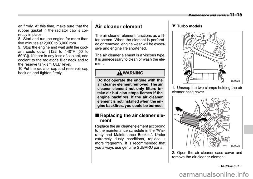
Turbo models
1. Unsnap the two clamps holding the air
cleaner case cover.
2. Open the air cleaner case cover and
remove the air cleaner element.
Do not operate the engine with the
air cleaner element removed. The air
cleaner element not only filters in-
take air but also stops flames if the
engine backfires. If the air cleaner
element is not installed when the en-
gine backfires, you could be burned.B00024
B00025
Page 315 of 365
11-36 Maintenance and service
Windshield washer fluid
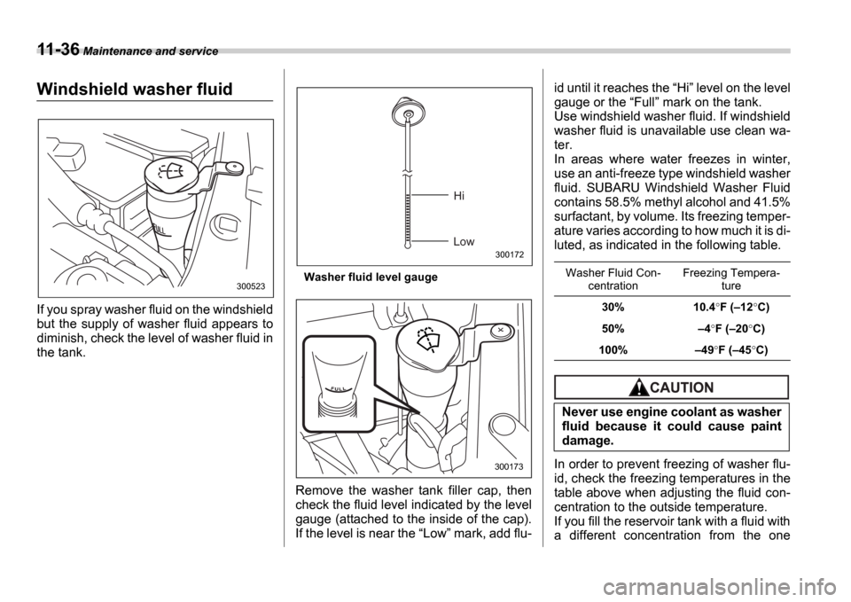
If you spray washer fluid on the windshield
but the supply of washer fluid appears to
diminish, check the level of washer fluid in
the tank.
Washer fluid level gauge
Remove the washer tank filler cap, then
check the fluid level indicated by the level
gauge (attached to the inside of the cap).
If the level is near the Low mark, add flu- id until it reaches the
Hi level on the level
gauge or the Full mark on the tank.
Use windshield washer fluid. If windshield
washer fluid is unavailable use clean wa-
ter.
In areas where water freezes in winter,
use an anti-freeze type windshield washer
fluid. SUBARU Windshield Washer Fluid
contains 58.5% methyl alcohol and 41.5%
surfactant, by volume. Its freezing temper-
ature varies according to how much it is di-
luted, as indicated in the following table.
In order to prevent freezing of washer flu-
id, check the freezing temperatures in the
table above when adjusting the fluid con-
centration to the outside temperature.
If you fill the reservoir tank with a fluid with
a different concentration from the one
300523
Hi
Low
300172
300173
Washer Fluid Con- centration Freezing Tempera-
ture
30% 10.4 F ( 12 C)
50% 4F ( 20 C)
100% 49 F ( 45 C)
Never use engine coolant as washer
fluid because it could cause paint
damage.
Page 335 of 365
12-4 Specifications
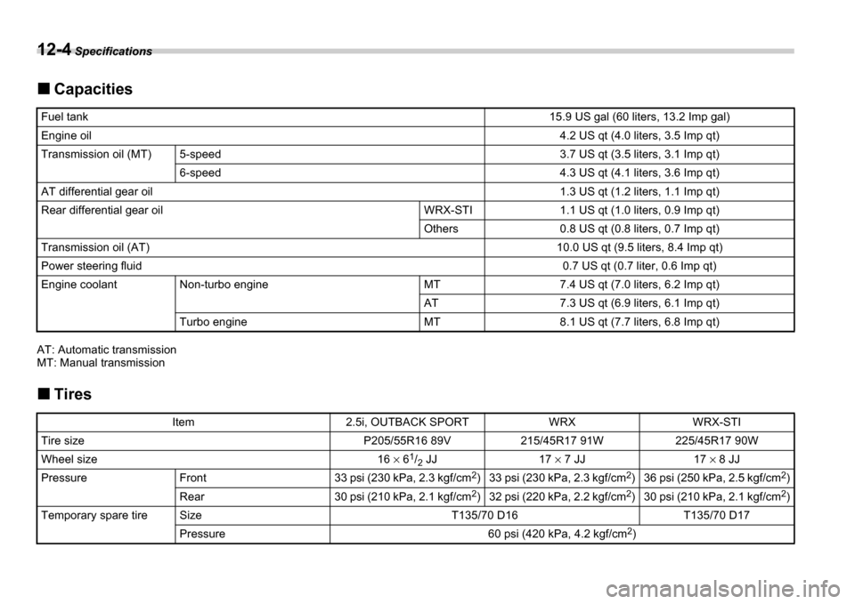
Capacities
AT: Automatic transmission
MT: Manual transmission
Tires
Fuel tank15.9 US gal (60 liters, 13.2 Imp gal)
Engine oil4.2 US qt (4.0 liters, 3.5 Imp qt)
Transmission oil (MT)5-speed3.7 US qt (3.5 liters, 3.1 Imp qt)
6-speed4.3 US qt (4.1 liters, 3.6 Imp qt)
AT differential gear oil1.3 US qt (1.2 liters, 1.1 Imp qt)
Rear differential gear oilWRX-STI1.1 US qt (1.0 liters, 0.9 Imp qt)
Others0.8 US qt (0.8 liters, 0.7 Imp qt)
Transmission oil (AT)10.0 US qt (9.5 liters, 8.4 Imp qt)
Power steering fluid0.7 US qt (0.7 liter, 0.6 Imp qt)
Engine coolantNon-turbo engineMT7.4 US qt (7.0 liters, 6.2 Imp qt)
AT7.3 US qt (6.9 liters, 6.1 Imp qt)
Turbo engineMT8.1 US qt (7.7 liters, 6.8 Imp qt)
Item2.5i, OUTBACK SPORTWRXWRX-STI
Tire sizeP205/55R16 89V215/45R17 91W225/45R17 90W
Wheel size16 6 1
/2 JJ17
7 JJ17 8 JJ
PressureFront33 psi (230 kPa, 2.3 kgf/cm 2
)33 psi (230 kPa, 2.3 kgf/cm 2
)36 psi (250 kPa, 2.5 kgf/cm 2
)
Rear30 psi (210 kPa, 2.1 kgf/cm 2
)32 psi (220 kPa, 2.2 kgf/cm 2
)30 psi (210 kPa, 2.1 kgf/cm 2
)
Temporary spare tireSizeT135/70 D16T135/70 D17
Pressure60 psi (420 kPa, 4.2 kgf/cm 2
)
Page 348 of 365
Consumer information and Reporting safety defects 13-7
CONTINUED
asymmetrical tire that has a particu-
lar side that must always face out-
ward when mounting on a vehicle.
Accessory weight
The combined weight (in excess of
those standard items which may be
replaced) of floor mats, leather seats
and cross bars to the extent that these
items are available as factory-in-
stalled equipment (whether installed
or not).
Curb weight
The weight of a motor vehicle with
standard equipment including the
maximum capacity of fuel, oil, and
coolant and air conditioning.
Maximum loaded vehicle weight
The sum of curb weight, accessory
weight, vehicle capacity weight and
production options weight.
Normal occupant weight
150 lbs (68 kg) times the number of
occupants (3 occupants).
Occupant distribution
Distribution of occupants in a vehicle,
2 in front, 1 in rear seat.
Production options weight
The combined weight of those in-
stalled regular production options weighing over 5.1 lbs (2.3 kg) in ex-
cess of those standards items which
they replace, not previously consid-
ered in curb weight or accessory
weight.
Vehicle capacity weight
The total weight of cargo, luggage
and occupants that can be added to
the vehicle.
Vehicle maximum load on a tire
Load on an individual tire that is deter-
mined by distributing to each axle its
share of the maximum loaded vehicle
weight and dividing by two.
Vehicle normal load on a tire
Load on an individual tire that is deter-
mined by distributing to each axle its
share of the curb weight, accessory
weight, and normal occupant weight
and dividing by two.
Tire care maintenance and
safety practices
Check on a daily basis that the tires
are free from serious damage, nails,
and stones. At the same time, check
the tires for abnormal wear.
Inspect the tire tread regularly and
replace the tires before their tread wear indicators become visible. When
a tire
s tread wear indicator becomes
visible, the tire is worn beyond the ac-
ceptable limit and must be replaced
immediately. With a tire in this condi-
tion, driving at even low speeds in wet
weather can cause the vehicle to hy-
droplane. Possible resulting loss of
vehicle control can lead to an acci-
dent.
To maximize the life of each tire and
ensure that the tires wear uniformly, it
is best to rotate the tires every 7,500
miles (12,500 km). Rotating the tires
involves switching the front and rear
tires on the right-hand side of the ve-
hicle and similarly switching the front
and rear tires on the left-hand side of
the vehicle. (Each tire must be kept on
its original side of the vehicle.) Re-
place any damaged or unevenly worn
tire at the time of rotation. After tire ro-
tation, adjust the tire pressures and
make sure the wheel nuts are correct-
ly tightened. A tightening torque spec-
ification and a tightening sequence
specification for the wheel nuts can be
found Flat tires section in chapter 9.
Page 359 of 365
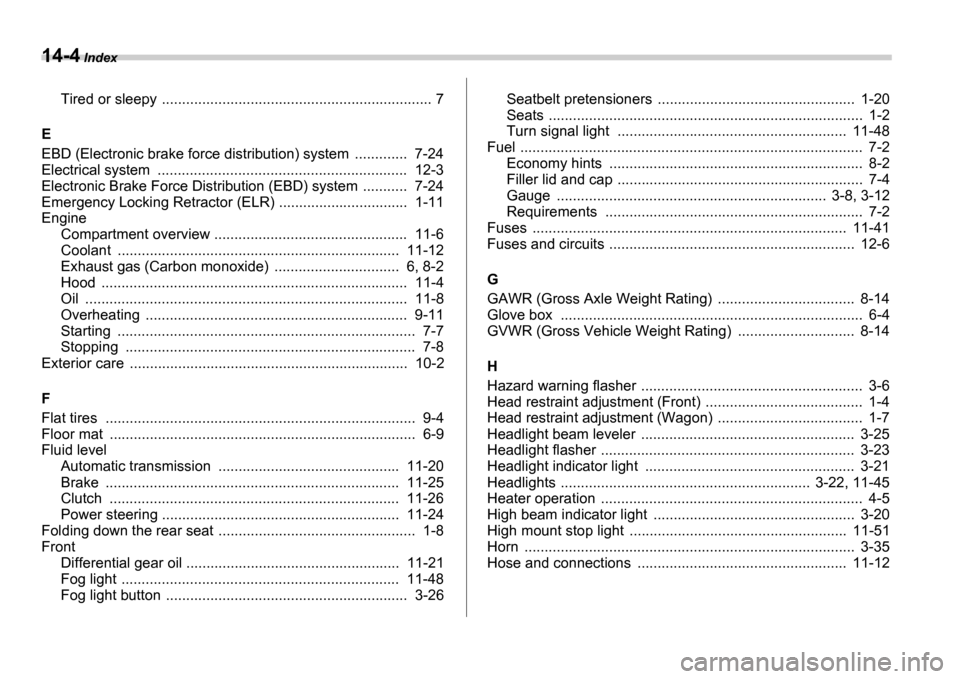
14-4 Index
Tired or sleepy .................................... ............................... 7
E
EBD (Electronic brake force distribution) system ........ ..... 7-24
Electrical system ..................................... ......................... 12-3
Electronic Brake Force Distribution (EBD) system ......... .. 7-24
Emergency Locking Retractor (ELR) .................... ............ 1-11
Engine Compartment overview ................................ ................ 11-6
Coolant ........................................... ........................... 11-12
Exhaust gas (Carbon monoxide) ....................... ........ 6, 8-2
Hood .............................................. .............................. 11-4
Oil ............................................... ................................. 11-8
Overheating ........................................ ......................... 9-11
Starting .......................................... ................................ 7-7
Stopping .......................................... .............................. 7-8
Exterior care ....................................... .............................. 10-2
F
Flat tires ......................................... .................................... 9-4
Floor mat ......................................... ................................... 6-9
Fluid level
Automatic transmission ............................... .............. 11-20
Brake .............................................. ........................... 11-25
Clutch ............................................. ........................... 11-26
Power steering ..................................... ...................... 11-24
Folding down the rear seat ......................... ........................ 1-8
Front
Differential gear oil ............................. ........................ 11-21
Fog light ......................................... ............................ 11-48
Fog light button .................................. .......................... 3-26Seatbelt pretensioners ..............................
................... 1-20
Seats .............................................. ................................ 1-2
Turn signal light .................................. ....................... 11-48
Fuel .............................................. ....................................... 7-2
Economy hints ........................................ ....................... 8-2
Filler lid and cap ................................. ............................ 7-4
Gauge ............................................. ...................... 3-8, 3-12
Requirements ...................................... .......................... 7-2
Fuses .............................................. ................................ 11-41
Fuses and circuits ..................................... ........................ 12-6
G
GAWR (Gross Axle Weight Rating) ..................... ............. 8-14
Glove box ........................................... ................................ 6-4
GVWR (Gross Vehicle Weight Rating) ................... .......... 8-14
H
Hazard warning flasher ............................. .......................... 3-6
Head restraint adjustment (Front) ................... .................... 1-4
Head restraint adjustment (Wagon) .................. .................. 1-7
Headlight beam leveler ............................ ......................... 3-25
Headlight flasher .................................. ............................. 3-23
Headlight indicator light .......................... .......................... 3-21
Headlights ......................................... ..................... 3-22, 11-45
Heater operation .................................. ............................... 4-5
High beam indicator light .......................... ........................ 3-20
High mount stop light .............................. ........................ 11-51
Horn .............................................. .................................... 3-35
Hose and connections .................................. .................. 11-12