brake light SUBARU IMPREZA WRX 2006 2.G Owner's Guide
[x] Cancel search | Manufacturer: SUBARU, Model Year: 2006, Model line: IMPREZA WRX, Model: SUBARU IMPREZA WRX 2006 2.GPages: 365, PDF Size: 7.09 MB
Page 276 of 365
Appearance care 10-3
CONTINUED
with plenty of lukewarm water. Wipe the
remaining water off with a chamois or soft
cloth.
Washing the underbody
Chemicals, salts and gravel used for deic-
ing road surfaces are extremely corrosive,
accelerating the corrosion of underbody
components, such as the exhaust system,
fuel and brake lines, brake cables, floor
pan and fenders, and suspension.
Thoroughly flush the underbody and in-
side of the fenders with lukewarm or cold
water at frequent intervals to reduce the
harmful effects of such agents.
Mud and sand adhering to the underbody
components may accelerate their corro-
sion.
After driving off-road or on muddy or
sandy roads, wash the mud and sand off
the underbody. Carefully flush the sus-
pension and axle parts, as they are partic-
ularly prone to mud and sand buildup. Do
not use a sharp-edged tool to remove
caked mud.
NOTE
Be careful not to damage brake hoses,
sensor harnesses, and other parts
when washing suspension compo-
nents.
Using a warm water washer
Keep a good distance of 12 in (30 cm)
or more between the washer nozzle and
the vehicle.
Do not wash the same area continuous-
ly.
If a stain will not come out easily, wash
by hand. Some warm water washers are
of the high temperature, high pressure
type, and they can damage or deform the
resin parts such as mouldings, or cause
water to leak into the vehicle.
Waxing and polishing
Always wash and dry the vehicle before
waxing and polishing.
Use a good quality polish and wax and ap-
ply them according to the manufacturer s
instructions. Wax or polish when the paint-
ed surface is cool.
Be sure to polish and wax the chrome trim,
as well as the painted surfaces. Loss of
wax on a painted surface leads to loss of
the original luster and also quickens the
deterioration of the surface. It is recom-
mended that a coat of wax be applied at
least once a month, or whenever the sur-
face no longer repels water.
If the appearance of the paint has dimin-
ished to the point where the luster or tone cannot be restored, lightly polish the sur-
face with a fine-grained compound. Never
polish just the affected area, but include
the surrounding area as well. Always pol-
ish in only one direction. A No. 2000 grain
compound is recommended. Never use a
coarse-grained compound. Coarser
grained compounds have a smaller grain-
size number and could damage the paint.
After polishing with a compound, coat with
wax to restore the original luster. Frequent
polishing with a compound or an incorrect
polishing technique will result in removing
the paint layer and exposing the under-
coat. When in doubt, it is always best to
contact your SUBARU dealer or an auto
paint specialist.
NOTE
Be careful not to block the windshield
washer nozzles with wax when waxing
the vehicle.
Cleaning aluminum wheels
Promptly wipe the aluminum wheels
clean of any kind of grime or agent. If dirt
is left on too long, it may be difficult to
clean off.
Do not use soap containing grit to clean
the wheels. Be sure to use a neutral clean-
ing agent, and later rinse thoroughly with
water. Do not clean the wheels with a stiff
Page 306 of 365
Maintenance and service 11-27
Brake booster
If the brake booster does not operate as
described in the following, have it checked
by your SUBARU dealer.
1. With the engine off, depress the brake
pedal several times, applying the same
pedal force each time. The distance the
pedal travels should not vary.
2. With the brake pedal depressed, start
the engine. The pedal should move slight-
ly down to the floor.
3. With the brake pedal depressed, stop
the engine and keep the pedal depressed
for 30 seconds. The pedal height should
not change.
4. Start the engine again and run for ap-
proximately one minute then turn it off.
Depress the brake pedal several times to
check the brake booster. The brake boost-
er operates properly if the pedal stroke de-
creases with each depression.
Brake pedal
Check the brake pedal free play and re-
serve distance according to the mainte-
nance schedule in the Warranty and
Maintenance Booklet .
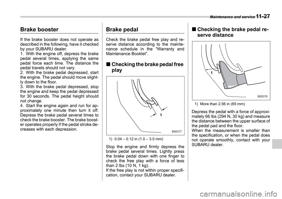
Checking the brake pedal free
play
1) 0.04 0.12 in (1.0 3.0 mm)
Stop the engine and firmly depress the
brake pedal several times. Lightly press
the brake pedal down with one finger to
check the free play with a force of less
than 2 lbs (10 N, 1 kg).
If the free play is not within proper specifi-
cation, contact your SUBARU dealer.
Checking the brake pedal re-
serve distance
1) More than 2.56 in (65 mm)
Depress the pedal with a force of approxi-
mately 66 lbs (294 N, 30 kg) and measure
the distance between the upper surface of
the pedal pad and the floor.
When the measurement is smaller than
the specification, or when the pedal does
not operate smoothly, contact with your
SUBARU dealer.1
B00377
1
B00378
Page 307 of 365
11-28 Maintenance and service
Clutch pedal (MT vehicles)
Check the clutch pedal free play and re-
serve distance according to the mainte-
nance schedule in the Warranty and
Maintenance Booklet .
Checking the clutch function
Check the clutch engagement and disen-
gagement.
1. With the engine idling, check that there
are no abnormal noises when the clutch
pedal is depressed, and that shifting into
1st or reverse feels smooth.
2. Start the vehicle by releasing the pedal
slowly to check that the engine and trans-
mission smoothly couple without any sign
of slippage.
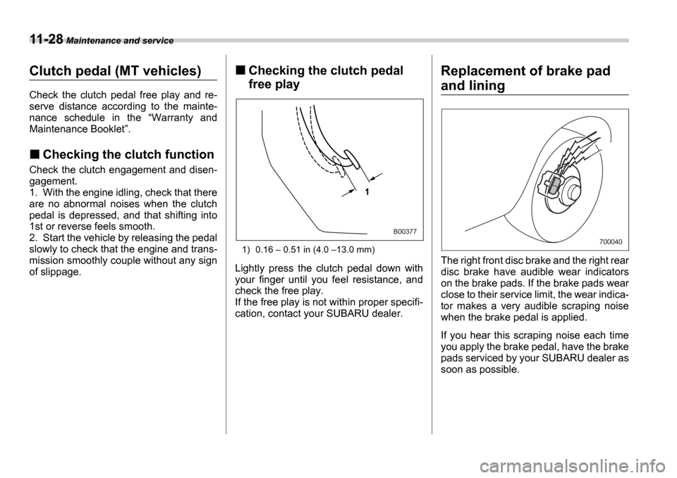
Checking the clutch pedal
free play
1) 0.16 0.51 in (4.0 13.0 mm)
Lightly press the clutch pedal down with
your finger until you feel resistance, and
check the free play.
If the free play is not within proper specifi-
cation, contact your SUBARU dealer.
Replacement of brake pad
and lining
The right front disc brake and the right rear
disc brake have audible wear indicators
on the brake pads. If the brake pads wear
close to their service limit, the wear indica-
tor makes a very audible scraping noise
when the brake pedal is applied.
If you hear this scraping noise each time
you apply the brake pedal, have the brake
pads serviced by your SUBARU dealer as
soon as possible.
1
B00377
700040
Page 308 of 365
Maintenance and service 11-29
Breaking-in of new brake
pads and linings
When replacing the brake pad or lining,
use only genuine SUBARU parts. After re-
placement, the new parts must be broken
in as follows:
Brake pad and lining
While maintaining a speed of 30 to 40 mph
(50 to 65 km/h), step on the brake pedal
lightly. Repeat this five or more times.
Parking brake lining
1. Drive the vehicle at a speed of approx-
imately 22 mph (35 km/h).
2. With the parking brake release button
pushed in, pull the parking brake lever
SLOWLY and GENTLY. (Pulling with a
force of approximately 33 lbs [147 N, 15
kg].)
3. Drive the vehicle for approximately 220
yards (200 meters) in this condition.
4. Wait 5 to 10 minutes for the parking brake to cool down. Repeat this proce-
dure.
5. Check the parking brake stroke. If the
parking brake stroke is out of the specified
range, adjust it by turning the adjusting nut
located on the parking brake lever.
Parking brake stroke:
7
8 notches / 44 lbs (196 N, 20 kg)
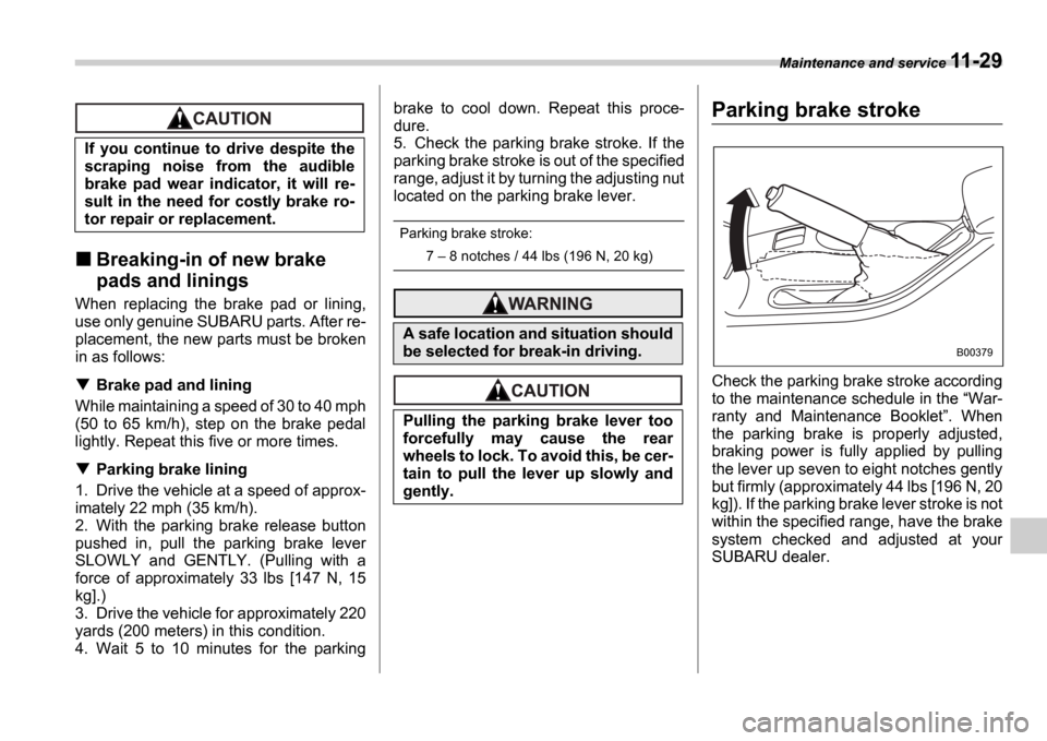
Parking brake stroke
Check the parking brake stroke according
to the maintenance schedule in the War-
ranty and Maintenance Booklet . When
the parking brake is properly adjusted,
braking power is fully applied by pulling
the lever up seven to eight notches gently
but firmly (approximately 44 lbs [196 N, 20
kg]). If the parking brake lever stroke is not
within the specified range, have the brake
system checked and adjusted at your
SUBARU dealer.
If you continue to drive despite the
scraping noise from the audible
brake pad wear indicator, it will re-
sult in the need for costly brake ro-
tor repair or replacement.
A safe location and situation should
be selected for break-in driving.
Pulling the parking brake lever too
forcefully may cause the rear
wheels to lock. To avoid this, be cer-
tain to pull the lever up slowly and
gently.
B00379
Page 324 of 365
Maintenance and service 11-45
CONTINUED
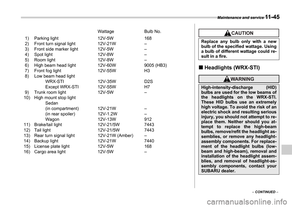
Wattage Bulb No.
1) Parking light 12V-5W 168
2) Front turn signal light 12V-21W
3) Front side marker light 12V-5W
4) Spot light 12V-8W
5) Room light 12V-8W
6) High beam head light 12V-60W 9005 (HB3)
7) Front fog light 12V-55W H3
8) Low beam head light WRX-STI 12V-35W D2S
Except WRX-STI 12V-55W H7
9) Trunk room light 12V-5W
10) High mount stop light
Sedan
(in compartment) 12V-21W
(in rear spoiler) 12V-1.2W
Wagon 12V-13W 912
11) Brake/tail light 12V-21/5W 7443
12) Tail light 12V-21/5W 7443
13) Rear turn signal light 12V-21W (Amber)
14) Backup light 12V-21W 7440
15) License plate light 12V-5W 168
16) Cargo area light 12V-5W
Headlights (WRX-STI)
Replace any bulb only with a new
bulb of the specified wattage. Using
a bulb of different wattage could re-
sult in a fire.
High-intensity-discharge (HID)
bulbs are used for the low beams of
the headlights on the WRX-STI.
These HID bulbs use an extremely
high voltage. To avoid the risk of an
electric shock and resulting serious
injury, you should not attempt to re-
place them. Neither should you at-
tempt to replace the high-beam
bulbs, remove/refit the headlight as-
semblies, or remove any headlight-
assembly components. For replace-
ment of the headlight bulbs (low-
beam and high-beam), removal and
installation of the headlight assem-
blies, and removal of headlight-as-
sembly components, contact your
SUBARU dealer.
Page 327 of 365
11-48 Maintenance and service
3. Replace the bulb with new one.
4. Reconnect the electrical connector. At
this time, use care not to touch the bulb
surface.
5. To install the bulb to the headlight as-
sembly, turn it clockwise until it clicks.
Front turn signal light bulbs
It may be difficult to replace the bulbs.
Have your SUBARU dealer replace the
bulbs if necessary.
Parking light
It may be difficult to replace the bulbs.
Have your SUBARU dealer replace the
bulbs if necessary.
Front fog light
It may be difficult to replace the bulbs.
Have your SUBARU dealer replace the
bulbs if necessary.
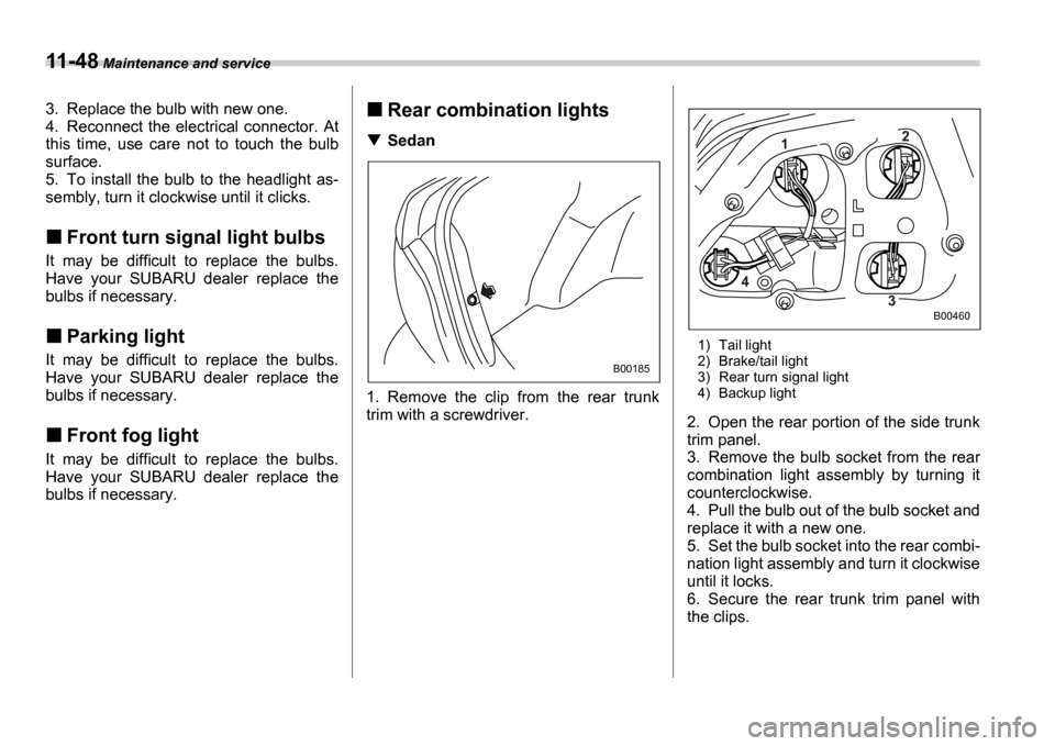
Rear combination lights
Sedan
1. Remove the clip from the rear trunk
trim with a screwdriver.
1) Tail light
2) Brake/tail light
3) Rear turn signal light
4) Backup light
2. Open the rear portion of the side trunk
trim panel.
3. Remove the bulb socket from the rear
combination light assembly by turning it
counterclockwise.
4. Pull the bulb out of the bulb socket and
replace it with a new one.
5. Set the bulb socket into the rear combi-
nation light assembly and turn it clockwise
until it locks.
6. Secure the rear trunk trim panel with
the clips.
B00185
1 2
3
4
B00460
Page 328 of 365
Maintenance and service 11-49
CONTINUED
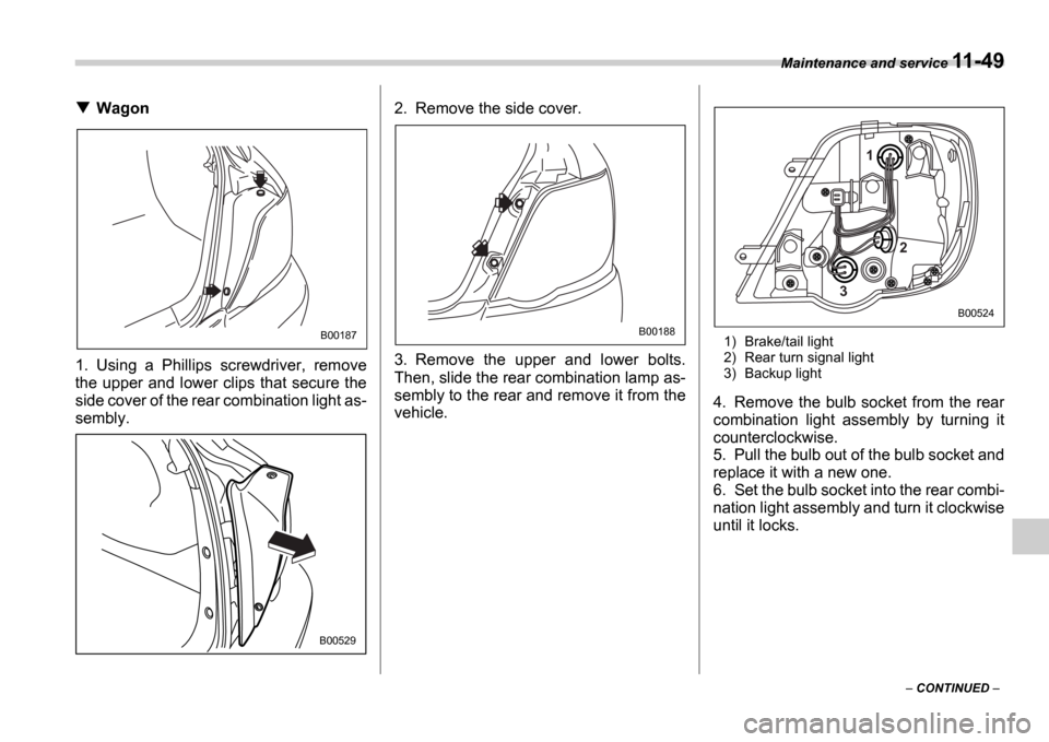
Wagon
1. Using a Phillips screwdriver, remove
the upper and lower clips that secure the
side cover of the rear combination light as-
sembly. 2. Remove the side cover.
3. Remove the upper and lower bolts.
Then, slide the rear combination lamp as-
sembly to the rear and remove it from the
vehicle.
1) Brake/tail light
2) Rear turn signal light
3) Backup light
4. Remove the bulb socket from the rear
combination light assembly by turning it
counterclockwise.
5. Pull the bulb out of the bulb socket and
replace it with a new one.
6. Set the bulb socket into the rear combi-
nation light assembly and turn it clockwise
until it locks.
B00187
B00529
B00188
1
3 2
B00524
Page 338 of 365
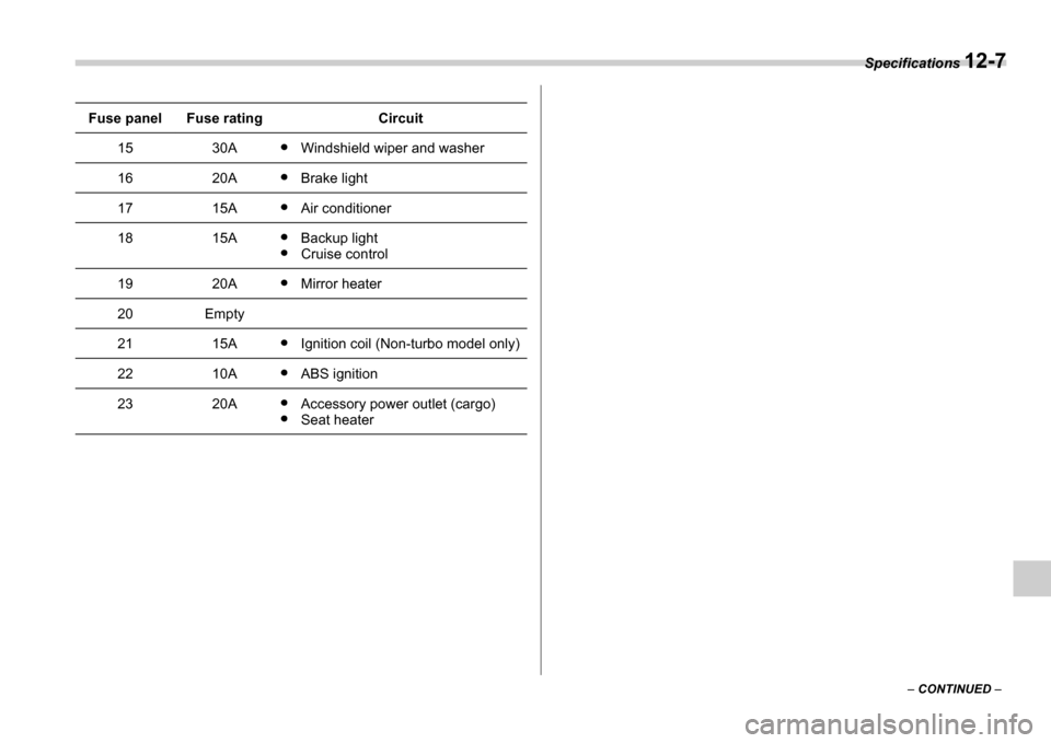
Specifications 12-7
CONTINUED
1530AWindshield wiper and washer
1620ABrake light
1715AAir conditioner
1815ABackup light
Cruise control
1920AMirror heater
20Empty
2115AIgnition coil (Non-turbo model only)
2210AABS ignition
2320AAccessory power outlet (cargo)
Seat heater
Fuse panelFuse ratingCircuit
Page 340 of 365

Specifications 12-9
Bulb chart
Description Wattage Bulb type
Headlight
WRX-STI versionLow beam 12V-35W D2S
High beam 12V-60W 9005 (HB3)
Except WRX-STI ver-
sion Low beam 12V-55W H7
High beam 12V-60W 9005 (HB3)
Front fog light 12V-55W H3
Front turn signal light 12V-21W
Parking light 12V-5W 168
Front side marker light 12V-5W
Rear combination light
Brake/tail light 12V-21/5W 7443
Turn signal light 12V-21W (Amber)
Backup light 12V-21W 7440
High mount stop light Sedan (in compartment) 12V-21W
Sedan (in rear spoiler) 12V-1.2W
Wagon 12V-13W 912
License plate light 12V-5W 168
Trunk room light 12V-5W
Cargo area light 12V-5W
Front ashtray light 12V-1.4W
Dome light 12V-8W
Map light 12V-8W
Page 357 of 365
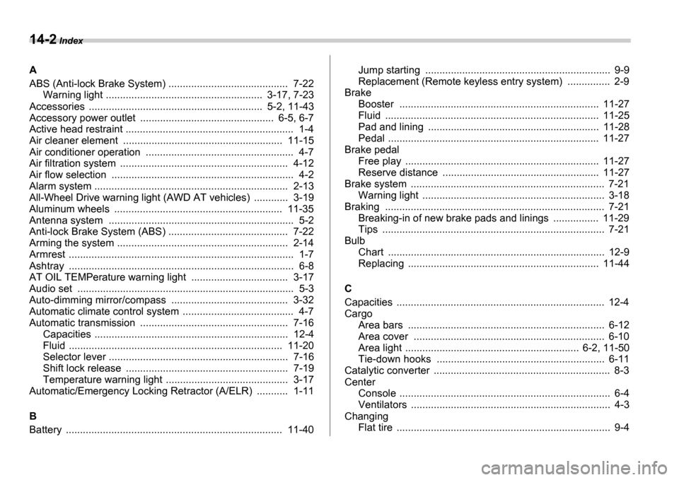
14-2 Index
A
ABS (Anti-lock Brake System) .......................... ................ 7-22
Warning light ..................................... .................. 3-17, 7-23
Accessories ........................................... .................. 5-2, 11-43
Accessory power outlet ................................. .............. 6-5, 6-7
Active head restraint ............................... ............................ 1-4
Air cleaner element ................................ ........................ 11-15
Air conditioner operation ......................... ........................... 4-7
Air filtration system ............................... ............................ 4-12
Air flow selection .................................. .............................. 4-2
Alarm system ........................................ ............................ 2-13
All-Wheel Drive warning light (AWD AT vehicles) ..... ....... 3-19
Aluminum wheels .................................... ....................... 11-35
Antenna system ...................................... ........................... 5-2
Anti-lock Brake System (ABS) .......................... ................ 7-22
Arming the system ................................... ......................... 2-14
Armrest ............................................ ................................... 1-7
Ashtray ............................................. .................................. 6-8
AT OIL TEMPerature warning light .................. ................ 3-17
Audio set .......................................... .................................. 5-3
Auto-dimming mirror/compass .......................... ............... 3-32
Automatic climate control system ........................ ............... 4-7
Automatic transmission ............................... ..................... 7-16
Capacities .......................................... .......................... 12-4
Fluid ............................................. .............................. 11-20
Selector lever ...................................... ......................... 7-16
Shift lock release ................................... ...................... 7-19
Temperature warning light ......................... .................. 3-17
Automatic/Emergency Locking Retractor (A/ELR) ........... 1-11
B
Battery ............................................ ................................ 11-40 Jump starting .......................................
.......................... 9-9
Replacement (Remote keyless entry system) ............... 2-9
Brake Booster ............................................ .......................... 11-27
Fluid ............................................. .............................. 11-25
Pad and lining .................................... ........................ 11-28
Pedal ............................................. ............................. 11-27
Brake pedal Free play .......................................... .......................... 11-27
Reserve distance ...................................... ................. 11-27
Brake system ......................................... ........................... 7-21
Warning light ..................................... ........................... 3-18
Braking ............................................ ................................. 7-21
Breaking-in of new brake pads and linings ............ .... 11-29
Tips ............................................... ............................... 7-21
Bulb Chart ............................................. ............................... 12-9
Replacing ......................................... .......................... 11-44
C
Capacities .......................................... ............................... 12-4
Cargo Area bars .......................................... ........................... 6-12
Area cover .......................................... ......................... 6-10
Area light ........................................ ..................... 6-2, 11-50
Tie-down hooks ...................................... ..................... 6-11
Catalytic converter ................................... ........................... 8-3
Center Console ............................................ .............................. 6-4
Ventilators ........................................ .............................. 4-3
Changing Flat tire ......................................... .................................. 9-4