battery SUBARU IMPREZA WRX 2006 2.G Owners Manual
[x] Cancel search | Manufacturer: SUBARU, Model Year: 2006, Model line: IMPREZA WRX, Model: SUBARU IMPREZA WRX 2006 2.GPages: 365, PDF Size: 7.09 MB
Page 33 of 365
1-6 Seat, seatbelt and SRS airbags
NOTE
Use of the seat heater for a long period
of time while the engine is not running
can cause battery discharge.
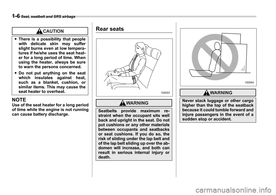
Rear seats
There is a possibility that people
with delicate skin may suffer
slight burns even at low tempera-
tures if he/she uses the seat heat-
er for a long period of time. When
using the heater, always be sure
to warn the persons concerned.
Do not put anything on the seat
which insulates against heat,
such as a blanket, cushion, or
similar items. This may cause the
seat heater to overheat.
Seatbelts provide maximum re-
straint when the occupant sits well
back and upright in the seat. Do not
put cushions or any other materials
between occupants and seatbacks
or seat cushions. If you do so, the
risk of sliding under the lap belt and
of the lap belt sliding up over the ab-
domen will increase, and both can
result in serious internal injury or
death.
100093
Never stack luggage or other cargo
higher than the top of the seatback
because it could tumble forward and
injure passengers in the event of a
sudden stop or accident.
100094
Page 45 of 365
1-18 Seat, seatbelt and SRS airbags
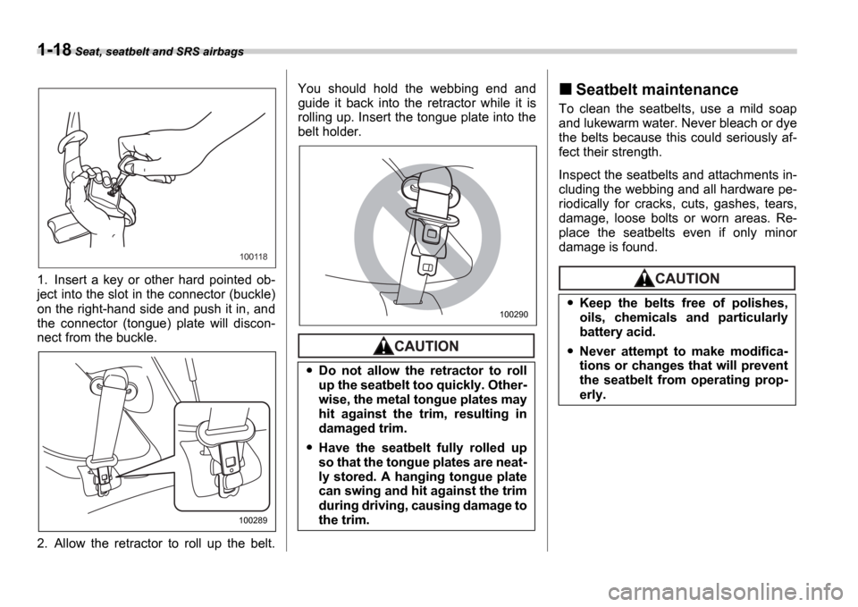
1. Insert a key or other hard pointed ob-
ject into the slot in the connector (buckle)
on the right-hand side and push it in, and
the connector (tongue) plate will discon-
nect from the buckle.
2. Allow the retractor to roll up the belt. You should hold the webbing end and
guide it back into the retractor while it is
rolling up. Insert the tongue plate into the
belt holder.
Seatbelt maintenance
To clean the seatbelts, use a mild soap
and lukewarm water. Never bleach or dye
the belts because this could seriously af-
fect their strength.
Inspect the seatbelts and attachments in-
cluding the webbing and all hardware pe-
riodically for cracks, cuts, gashes, tears,
damage, loose bolts or worn areas. Re-
place the seatbelts even if only minor
damage is found.
100118
100289
Do not allow the retractor to roll
up the seatbelt too quickly. Other-
wise, the metal tongue plates may
hit against the trim, resulting in
damaged trim.
Have the seatbelt fully rolled up
so that the tongue plates are neat-
ly stored. A hanging tongue plate
can swing and hit against the trim
during driving, causing damage to
the trim.
100290Keep the belts free of polishes,
oils, chemicals and particularly
battery acid.
Never attempt to make modifica-
tions or changes that will prevent
the seatbelt from operating prop-
erly.
Page 88 of 365

2
Keys and doors
Keys ..................................................................... 2-2
Key number ........................................ ..................... 2-2
Immobilizer (Turbo models) ......................... ..... 2-3
Security ID plate ................................. .................... 2-3
Security indicator light .......................... ................. 2-3
Key replacement ................................... .................. 2-4
Door locks ........................................ ................... 2-4
Locking and unlocking from the outside ............ . 2-4
Locking and unlocking from the inside ............. ... 2-5
Key lock-in prevention function ................... ......... 2-5
Power door locking switches ....................... ..... 2-6
Remote keyless entry system ....................... .... 2-7
Locking the doors ................................. ................. 2-7
Unlocking the doors ............................... ................ 2-8
Illuminated entry ................................. .................... 2-8
Vehicle finder function ........................... ................ 2-8
Sounding a panic alarm ............................ ............. 2-8
Selecting audible signal operation ................ ....... 2-8
Replacing the battery ............................. ................ 2-9
Replacing lost transmitters ....................... ............ 2-10
Alarm system ...................................... ................ 2-13
System alarm operation ............................ ............. 2-13
Activating and deactivating the alarm system ..... 2 -13
If you have accidentally triggered the alarm
system ............................................ ....................... 2-14
Arming the system ................................. ................ 2-14
Disarming the system .............................. .............. 2-15
Valet mode ........................................ ...................... 2-16
Passive arming .................................... ................... 2-16Tripped sensor identification .....................
........... 2-17
Shock sensors (dealer option) ..................... ......... 2-17
Child safety locks ................................ ............... 2-18
Windows ........................................... ................... 2-18
Power windows ..................................... .................. 2-18
Trunk lid (Sedan) ................................. ............... 2-20
To open and close the trunk lid from outside ...... 2-20
To open the trunk lid from inside ................. ......... 2-21
To cancel the trunk lid release ................... ........... 2-21
Internal trunk lid release handle ................. ........... 2-21
Rear gate (Wagon) ................................. ............. 2-23
Moonroof (if equipped) ............................ .......... 2-24
Tilt function ..................................... ........................ 2-24
Sliding function .................................. ..................... 2-24
Sun shades ........................................ ...................... 2-25
Page 96 of 365
Keys and doors 2-9
CONTINUED
seconds after Step 3.
5. While still holding down the
UNLOCK
side of the power door locking switch,
close the driver s door once within 10 sec-
onds after Step 4.
6. The turn signal lights flashes 3 times to
indicate completion of the setting.
NOTE
If you do not close the driver s door
within 10 seconds after Step 4, a flash
of the turn signal lights will signal time-
out. If this happens, repeat the whole
procedure from Step 1.
You may have the above settings done by
your SUBARU dealer.
Replacing the battery
When the transmitter battery begins to get
weak, transmitter range will begin to de-
crease. Replace the battery as soon as
possible. To replace the battery:
0
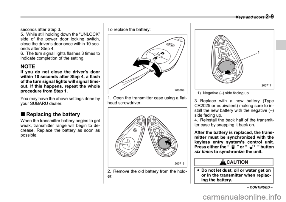
1. Open the transmitter case using a flat-
head screwdriver.
2. Remove the old battery from the hold-
er.
1) Negative (
) side facing up
3. Replace with a new battery (Type
CR2025 or equivalent) making sure to in-
stall the new battery with the negative ( )
side facing up.
4. Reinstall the back half of the transmit-
ter case by snapping it back on.
After the battery is replaced, the trans-
mitter must be synchronized with the
keyless entry system s control unit.
Press either the or button
six times to synchronize the unit.
200809
200716
Do not let dust, oil or water get on
or in the transmitter when replac-
ing the battery.
1
200717
Page 97 of 365
2-10 Keys and doors
Replacing lost transmitters
If you lose a transmitter or want to pur-
chase additional transmitters (up to four
can be programmed), you should re-pro-
gram all of your transmitters for security
reasons. It is recommended that you have
your dealer program all of your transmit-
ters into your system.
Programming the transmitters
The keyless entry system is equipped with
a special code learning feature that allows
you to program new transmitter codes into
the system or to delete old ones. The sys-
tem can learn up to four unique transmitter
codes. The four transmitter codes may be
the same or different. Programming transmitter codes into
system:
Bag containing transmitter
Transmitter circuit board
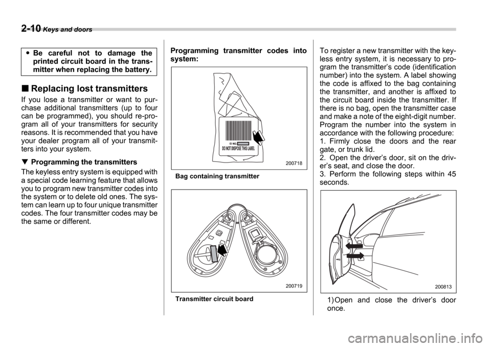
To register a new transmitter with the key-
less entry system, it is necessary to pro-
gram the transmitter
s code (identification
number) into the system. A label showing
the code is affixed to the bag containing
the transmitter, and another is affixed to
the circuit board inside the transmitter. If
there is no bag, open the transmitter case
and make a note of the eight-digit number.
Program the number into the system in
accordance with the following procedure:
1. Firmly close the doors and the rear
gate, or trunk lid.
2. Open the driver s door, sit on the driv-
er s seat, and close the door.
3. Perform the following steps within 45
seconds.
1) Open and close the driver s door
once.Be careful not to damage the
printed circuit board in the trans-
mitter when replacing the battery.
200718
200719200813
Page 103 of 365
2-16 Keys and doors
transmitter (i.e. the transmitter is lost, bro-
ken or the transmitter battery is too weak),
you can disarm the system without using
the transmitter.
1. Unlock the door with the key and then
open the door.
2. Insert the key into the ignition switch
and cycle it from the LOCK to the ON
position three times within 5 seconds.
Valet mode
When you choose the valet mode, the
alarm system does not operate. In valet
mode, the remote transmitter is used only
for locking and unlocking the doors and
rear gate (Wagon) and panic activation.
To enter the valet mode, change the set-
ting of your vehicle s alarm system for de-
activation mode. (Refer to Activating and
deactivating the alarm system in this sec-
tion.) The security indicator light will con-
tinue to flash once every three seconds in-
dicating that the system is in the valet
mode (only vehicle with an immobilizer).
To exit valet mode, change the setting of
your vehicle s alarm system for activation
mode. (Refer to Activating and deactivat-
ing the alarm system in this section.)
NOTE
If your vehicle is not equipped with an immobilizer, the security indicator light
does not flash during the valet mode.
Passive arming
When passive arming mode has been
programmed by the dealer, arming of the
system is automatically accomplished
without using the remote transmitter. Note
that in this mode, DOORS MUST BE
MANUALLY LOCKED.
To enter the passive mode
If you wish to program the passive arming
mode, have it done by your SUBARU
dealer.
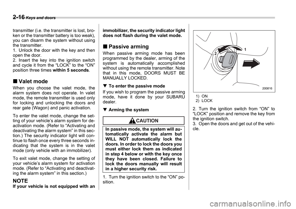
Arming the system
1. Turn the ignition switch to the ON po-
sition.
1) ON
2) LOCK
2. Turn the ignition switch from ON to
LOCK position and remove the key from
the ignition switch.
3. Open the doors and get out of the vehi-
cle.
In passive mode, the system will au-
tomatically activate the alarm but
WILL NOT automatically lock the
doors. In order to lock the doors you
must either lock them as indicated
in step 4 below or with the key once
they have been closed. Failure to
lock the doors manually will result
in a higher security risk.
1
2
200816
Page 111 of 365
2-24 Keys and doors
NOTE
If the rear gate cannot be unlocked due
to a discharged battery, a fault in the
door locking/unlocking system or oth-
er causes, you can unlock it by manu-
ally operating the rear gate lock release
lever.
For the procedure, refer to Rear gate
if the rear gate cannot be unlocked in
chapter 9 In case of emergency .
Moonroof (if equipped)
The moonroof has both tilting and sliding
functions.
The moonroof operates only when the ig-
nition switch is in the ON position.
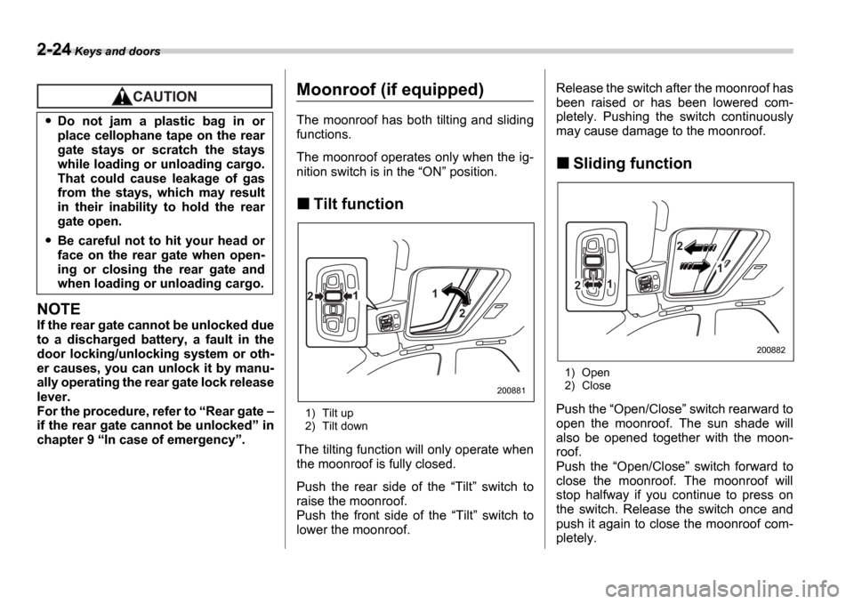
Tilt function
1) Tilt up
2) Tilt down
The tilting function will only operate when
the moonroof is fully closed.
Push the rear side of the Tilt switch to
raise the moonroof.
Push the front side of the Tilt switch to
lower the moonroof. Release the switch after the moonroof has
been raised or has been lowered com-
pletely. Pushing the switch continuously
may cause damage to the moonroof.
Sliding function
1) Open
2) Close
Push the Open/Close switch rearward to
open the moonroof. The sun shade will
also be opened together with the moon-
roof.
Push the Open/Close switch forward to
close the moonroof. The moonroof will
stop halfway if you continue to press on
the switch. Release the switch once and
push it again to close the moonroof com-
pletely.
Do not jam a plastic bag in or
place cellophane tape on the rear
gate stays or scratch the stays
while loading or unloading cargo.
That could cause leakage of gas
from the stays, which may result
in their inability to hold the rear
gate open.
Be careful not to hit your head or
face on the rear gate when open-
ing or closing the rear gate and
when loading or unloading cargo.
1
21
2
200881
2
1
12
200882
Page 117 of 365
3-4 Instruments and controls
NOTE
Keep the ignition switch in the
LOCK position when the engine is
not running.
Using electrical accessories for a
long time with the ignition switch in the ON or ACC position can cause the
battery to go dead.
If the ignition switch will not move from
the LOCK position to the ACC po-
sition, turn the steering wheel slightly
to the left and right as you turn the ig-
nition switch.
If the key is attached to a keyholder
or to a large bunch of other keys, cen-
trifugal force may act on it as the vehi-
cle moves, resulting in unwanted turn-
ing of the ignition switch. Also, if a
large keyholder is attached to the key,
your knees or hands may accidentally
touch it in a way that turns the ignition switch.
ACC
In this position the electrical accessories
(radio, cigarette lighter, etc.) can be used.
ON
This is the normal operating position after
the engine is started.
START
The engine is started in this position. The
starter cranks the engine to start it. When
the key is released (after the engine has
started), the key automatically returns to
the
ON position.
For vehicle with immobilizer
If your registered key fails to start the en-
gine, pull out the key once (the security in-
dicator light will blink), and then insert the
key in the ignition switch and turn it to the START position and again try to start the
engine.
NOTE
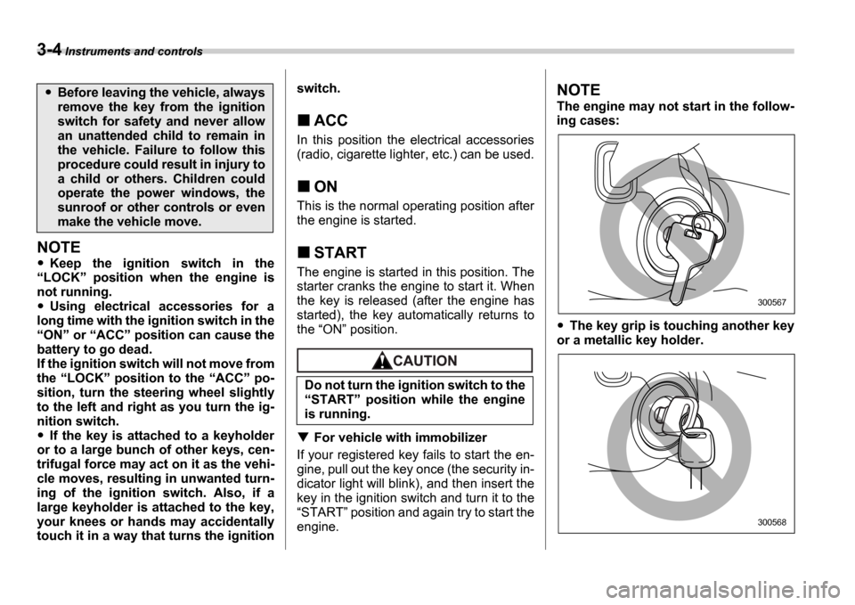
The engine may not start in the follow-
ing cases:
The key grip is touching another key
or a metallic key holder.
Before leaving the vehicle, always
remove the key from the ignition
switch for safety and never allow
an unattended child to remain in
the vehicle. Failure to follow this
procedure could result in injury to
a child or others. Children could
operate the power windows, the
sunroof or other controls or even
make the vehicle move.
Do not turn the ignition switch to the START position while the engine
is running.
300567
300568
Page 120 of 365
Instruments and controls 3-7
CONTINUED
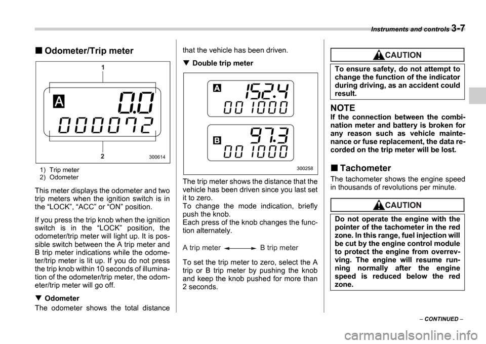
Odometer/Trip meter
1) Trip meter
2) Odometer
This meter displays the odometer and two
trip meters when the ignition switch is in
the LOCK , ACC or ON position.
If you press the trip knob when the ignition
switch is in the LOCK position, the
odometer/trip meter will light up. It is pos-
sible switch between the A trip meter and
B trip meter indications while the odome-
ter/trip meter is lit up. If you do not press
the trip knob within 10 seconds of illumina-
tion of the odometer/trip meter, the odom-
eter/trip meter will go off.
Odometer
The odometer shows the total distance that the vehicle has been driven.
Double trip meter
The trip meter shows the distance that the
vehicle has been driven since you last set
it to zero.
To change the mode indication, briefly
push the knob.
Each press of the knob changes the func-
tion alternately.
To set the trip meter to zero, select the A
trip or B trip meter by pushing the knob
and keep the knob pushed for more than
2 seconds.
NOTE
If the connection between the combi-
nation meter and battery is broken for
any reason such as vehicle mainte-
nance or fuse replacement, the data re-
corded on the trip meter will be lost.
Tachometer
The tachometer shows the engine speed
in thousands of revolutions per minute.
1
2
300614
300258
A trip meter B trip meter
To ensure safety, do not attempt to
change the function of the indicator
during driving, as an accident could
result.
Do not operate the engine with the
pointer of the tachometer in the red
zone. In this range, fuel injection will
be cut by the engine control module
to protect the engine from overrev-
ving. The engine will resume run-
ning normally after the engine
speed is reduced below the red
zone.
Page 125 of 365
3-12 Instruments and controls
NOTE
If the connection between the combi-
nation meter and battery is broken for
any reason such as vehicle mainte-
nance or fuse replacement, the data re-
corded on the trip meter will be lost.
Tachometer
The tachometer shows the engine speed
in thousands of revolutions per minute.
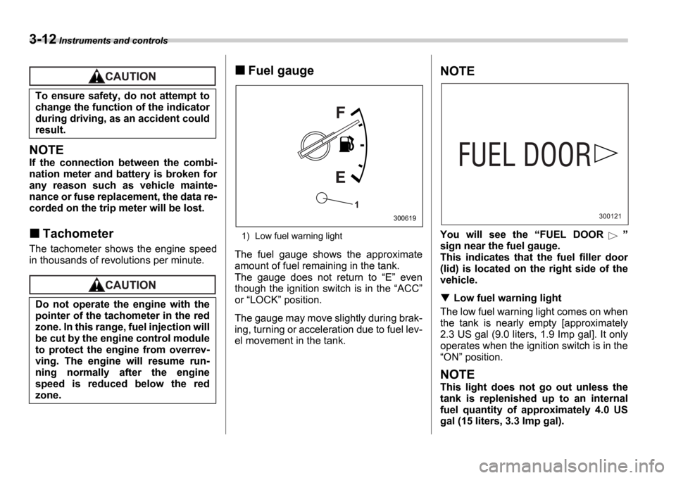
Fuel gauge
1) Low fuel warning light
The fuel gauge shows the approximate
amount of fuel remaining in the tank.
The gauge does not return to E even
though the ignition switch is in the ACC
or LOCK position.
The gauge may move slightly during brak-
ing, turning or acceleration due to fuel lev-
el movement in the tank.
NOTE
You will see the FUEL DOOR
sign near the fuel gauge.
This indicates that the fuel filler door
(lid) is located on the right side of the
vehicle.
Low fuel warning light
The low fuel warning light comes on when
the tank is nearly empty [approximately
2.3 US gal (9.0 liters, 1.9 Imp gal]. It only
operates when the ignition switch is in the ON position.
NOTE
This light does not go out unless the
tank is replenished up to an internal
fuel quantity of approximately 4.0 US
gal (15 liters, 3.3 Imp gal).
To ensure safety, do not attempt to
change the function of the indicator
during driving, as an accident could
result.
Do not operate the engine with the
pointer of the tachometer in the red
zone. In this range, fuel injection will
be cut by the engine control module
to protect the engine from overrev-
ving. The engine will resume run-
ning normally after the engine
speed is reduced below the red
zone.
1
300619300121