coolant SUBARU IMPREZA WRX 2007 3.G Owners Manual
[x] Cancel search | Manufacturer: SUBARU, Model Year: 2007, Model line: IMPREZA WRX, Model: SUBARU IMPREZA WRX 2007 3.GPages: 364, PDF Size: 11.91 MB
Page 117 of 364

3-8Instruments and controls
&Fuel gauge
1) Low fuel warning light
The fuel gauge shows the approximate
amount of fuel remaining in the tank.
When the ignition switch is in the “LOCK ”
or “Acc ”position, the fuel gauge shows “E ”
even if the fuel tank contains fuel.
The gauge may move slightly during
braking, turning or acceleration due to fuel
level movement in the tank. NOTE
You will see the
“”sign in the fuel
gauge meter.
This indicates that the fuel filler door
(lid) is located on the right side of thevehicle. ! Low fuel warning light
The low fuel warning light comes on when
the tank is nearly empty [Approximately
2.3 US gal (9.0 liters, 1.9 Imp gal)].
It only operates when the ignition switch is
in the “ON ”position.
NOTE
This light does not go out unless the
tank is replenished up to an internal fuel quantity of approximately 4.0 US
gal (15 liters, 3.3 Imp gal).
CAUTION
Promptly put fuel in the tank when-
ever the low fuel warning light
comes on. Engine misfires as a
result of an empty tank could cause
damage to the engine.
& Temperature gauge
1) Normal operating range
The temperature gauge shows engine
coolant temperature when the ignition
switch is in the “ON ”position.
The coolant temperature will vary in
Page 118 of 364
accordance with the outside temperature
and driving conditions.
We recommend that you drive moderately
until the pointer of the temperature gauge
reaches near the middle of the range.
Engine operation is optimum with the
engine coolant at this temperature range
and high revving operation when the
engine is not warmed up enough should
be avoided.
CAUTION
If the pointer exceeds the normal
operating range, safely stop the
vehicle as soon as possible.
See the “In case of emergency ”in
chapter 9. &
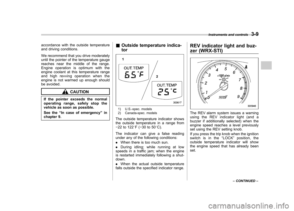
Outside temperature indica- tor
1) U.S.-spec. models
2) Canada-spec. models
The outside temperature indicator shows
the outside temperature in a range from� 22 to 122 8F( �30 to 50 8C).
The indicator can give a false reading
under any of the following conditions: . When there is too much sun.
. During idling; while running at low
speeds in a traffic jam; when the engine
is restarted immediately following a shut- down. . When the actual outside temperature
falls outside the specified indicator range. REV indicator light and buz-
zer (WRX-STI)The REV alarm system issues a warning
using the REV indicator light (and a
buzzer if additionally selected) when the
engine speed reaches a level previously
set using the REV setting knob.
If you press the trip knob when the ignition
switch is in the
“LOCK ”position, the
outside temperature indicator will show
the engine speed that has already beenset. Instruments and controls
3-9
– CONTINUED –
Page 122 of 364
fuel quantity of approximately 4.0 US
gal (15 liters, 3.3 Imp gal).
CAUTION
(Turbo model only)
Promptly put fuel in the tank when-
ever the low fuel warning light
comes on. Engine misfires as a
result of an empty tank could cause
damage to the engine.
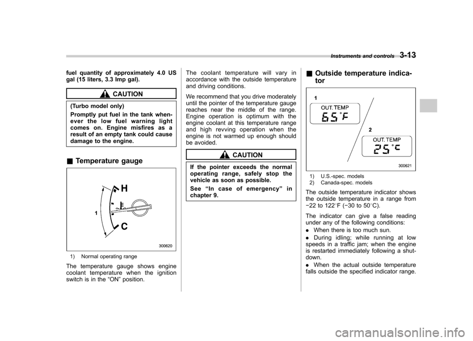
& Temperature gauge
1) Normal operating range
The temperature gauge shows engine
coolant temperature when the ignition
switch is in the “ON ”position. The coolant temperature will vary in
accordance with the outside temperature
and driving conditions.
We recommend that you drive moderately
until the pointer of the temperature gauge
reaches near the middle of the range.
Engine operation is optimum with the
engine coolant at this temperature range
and high revving operation when the
engine is not warmed up enough should
be avoided.
CAUTION
If the pointer exceeds the normal
operating range, safely stop the
vehicle as soon as possible. See “In case of emergency ”in
chapter 9. &
Outside temperature indica- tor
1) U.S.-spec. models
2) Canada-spec. models
The outside temperature indicator shows
the outside temperature in a range from� 22 to 122 8F( �30 to 50 8C).
The indicator can give a false reading
under any of the following conditions: . When there is too much sun.
. During idling; while running at low
speeds in a traffic jam; when the engine
is restarted immediately following a shut- down. . When the actual outside temperature
falls outside the specified indicator range. Instruments and controls
3-13
Page 152 of 364

4-8Climate control
Automatic climate control
system (if equipped)
Although this climate control system can
be used as a full-automatic climate control
system, it can also, if desired, be used as
a semi-automatic climate control system.
When it is used as a full-automatic climate
control system, the outlet air temperature,
fan speed, air flow distribution, air inlet
control, and air conditioner compressor
operation are all automatically controlled
to maintain a constant, comfortable tem-
perature inside the vehicle. NOTE .Operate the automatic climate con-
trol system when the engine is running. . When the engine coolant is cold, the
blower does not run.. In the “AUTO ”mode, when the air
temperature in the passenger compart-
ment is sufficiently cool, the air condi-
tioner compressor does not operate.
For efficient defogging or dehumidify-
ing in cold weather, press the “A/C ”
button to operate the air conditioner
compressor.. Even when cooling is not necessary,
setting the temperature much lower
than the current outlet air temperature
turns on the air conditioner compres- sor automatically and the
“A/C ”indi-
cator light on the control panel comeson. & Control panel
1) Air flow control dial
2) Fan speed control dial
3) Temperature control dial
4) Air conditioner button
5) Air inlet selection button
6) Rear window defogger button (Refer to
the“Rear window defogger button ”sec-
tion in chapter 3.)
& To use as full-automatic cli-
mate control system
Place the temperature control dial in the
position for your desired temperature, then
set the other dials and buttons as de- scribed in the following. The system
’s
functions will then switch to AUTO mode
and be controlled automatically. . Air flow control dial: AUTO position
. Fan speed control dial: AUTO position
. Air inlet selection button: Press for at
least 1 second. (Indicator will flash twice.). Air conditioner button: Press for at least
1 second. (Indicator will flash twice.)
& To use as semi-automatic
climate control system
Each function can be individually set to
AUTO mode independently of the others.
Any function set to AUTO mode is con-
trolled automatically. Any function not set
to AUTO mode can be manually adjusted
as desired.
The temperature can be set within a range
of 65 to 85 8F (20 to 30 8C).
Page 153 of 364

&Fan speed control dial
The fan operates only with the ignition
switch in the ON position. The fan speed
control dial is used to select the AUTO
(automatic control) mode or to select the
desired fan speed. The dial ’s positions
and their functions are as follows: OFF: The fan does not operate.
AUTO: The fan speed is adjusted auto-
maticallyinaccordancewiththeair
temperature inside and outside the pas-
senger compartment, the intensity of sun-
light, and other factors. SUBARU recom-
mends using the AUTO position.
Other positions: The fan speed can be
adjusted in 25 steps. NOTE
With the fan speed control dial in the
AUTO position and the air flow control
dial in the
“
”, “”,or “”position,
the fan does not operate during engine
warm-up until the engine coolant tem-
perature exceeds approx. 122 8F (50 8C).
& Temperature control dial
This dial is used to set the desired interior
temperature. With the dial set to your
desired temperature, the system automa-
tically adjusts the temperature of air
supplied from the outlets such that the
desired temperature is achieved andmaintained.
If the dial is turned fully counterclockwise,
the system gives maximum cooling per- formance. If the dial is turned fully clock-
wise, the system gives maximum heatingperformance. &
Air flow control dial
This dial has the following six positions.
The outlets from which air is supplied in
each position are as follows: AUTO: The air flow control is adjusted
automatically in accordance with the air
temperature inside and outside the pas-
senger compartment, the intensity of sun-
light, and other factors. SUBARU recom-
mends using the AUTO position.
: Instrument panel outlets
: Instrument panel outlets and foot
outlets
: Foot outlets and windshield defroster Climate control
4-9
– CONTINUED –
Page 203 of 364
7-6Starting and operating
CAUTION
Resultant vehicle damage due to
improper testing is not covered
under the SUBARU Limited War-
ranty and is the responsibility of
the state inspection program or its
contractors or licensees.
The EPA has issued regulations for
inspecting the On-Board Diagnostic
(OBD) system as part of the state emis-
sions inspection. The OBD system is
designed to detect engine and transmis-
sion problems that might cause vehicle
emissions to exceed allowable limits.
These inspections apply to all 1996 model
year and newer passenger cars and light
trucks. Over 30 states plus the District of
Columbia have implemented the OBD
system inspection. . The inspection of the OBD system
consists of a visual operational check of the “CHECK ENGINE ”warning light/mal-
function indicator lamp (MIL) and an
examination of the OBD system with an
electronic scan tool while the engine isrunning. . Avehicle
passes the OBD system
inspection if proper the “CHECK ENGINE ”
warning light/MIL illumination is observed,
there is nostored diagnostic trouble codes, and the OBD system readiness
monitors are complete. .
A vehicle
fails the OBD inspection if the
“ CHECK ENGINE ”warning light/MIL is
not properly operating or there are one or
more diagnostic trouble codes stored in
the vehicle ’s computer with the “CHECK
ENGINE ”warning light/MIL illuminated.
. A state emission inspection may reject
(not pass or fail) a vehicle if the number of
OBD system readiness monitors “Not
Ready ”is greater than one. Under this
condition, the vehicle operator should be
instructed to drive his/her vehicle for a few
days to set the monitors and return for an
emission re-inspection. . Owners of rejected or failing vehicles
should contact their SUBARU Dealer for service. Preparing to drive
You should perform the following checks
and adjustments every day before you
start driving.
1. Check that all windows, mirrors, and
lights are clean and unobstructed.
2. Check the appearance and condition
of the tires. Also check tires for properinflation.
3. Look under the vehicle for any sign of leaks.
4. Check that the hood, trunk (Sedan)
and rear gate (Wagon) are fully closed.
5. Check the adjustment of the seat.
6. Check the adjustment of the inside
and outside mirrors.
7. Fasten your seatbelt. Check that your
passengers have fastened their seatbelts.
8. Check the operation of the warning
and indicator lights when the ignition
switch is turned to the
“ON ”position.
9. Check the gauges, indicator and warn-
ing lights after starting the engine.
NOTE
Engine oil, engine coolant, brake fluid,
washer fluid and other fluid levels
should be checked daily, weekly or at
fuel stops.
Page 212 of 364

.When a temporary spare tire is
installed
. When your vehicle is towed
. When the vehicle is stopped
with the manual mode se- lected
NOTE . A higher initial LSD torque setting
gives the vehicle greater traction when
driving straight ahead but makes cor-
nering more difficult. Remember this
when adjusting the initial LSD torque.
In general, higher initial LSD torque
settings assist driving on slippery
roads and lower settings for non-slip-
pery roads. If you become stuck in
snow or mud, turning the center differ-
ential control dial to the frontmost
position will help move the vehicle
out. (The “LOCK ”indicator will come
on at the frontmost position.). During cornering or when making
turns (especially when getting into the
garage), the rotational difference be-
tween the front and rear wheels may
cause a braking effect accompanied by
vibration and noise. This does not
indicate a problem. The phenomenon
will disappear when you turn the center
differential control dial to the rearmost position (minimum initial LSD torqueposition).
In the auto mode, it controls the initial
LSD torque automatically. While in the
auto mode, this phenomenon some-
times occurs depending on the driving
condition, however, it does not indicate
a problem..
Use the center differential indicator
light only as a rough indication of the
initial LSD torque.. If you operate the center differential
control dial while quickly accelerating
or turning a tight corner, you may feel
slight shocks. This is due to differential
action by the center differential and
does not indicate a problem.
& Temporary release
When the driver stops the vehicle and
pulls the parking brake lever after manu-
ally setting the initial LSD torque, the LSD
torque is temporarily minimized. However
the indicator in the combination meter
continues to show the driver ’s selected
initial LSD torque. When the driver re-
leases the parking brake lever, the initial
LSD torque set by the driver is restored. Automatic transmission
The automatic transmission is electroni-
cally controlled and provides 4 forward
speeds and 1 reverse speed. NOTE .
When the engine coolant tempera-
ture is still low, your vehicle ’s auto-
matic transmission will up-shift at high-
er engine speeds than when the cool-
ant temperature is sufficiently high in
order to shorten the warm-up time and
improve driveability. The gearshift tim-
ing will automatically shift to the nor-
mal timing after the engine has warmedup. . Immediately after ATF (automatic
transmission fluid) is replaced, you
may feel that the automatic transmis-
sion operation is somewhat unusual.
This results from invalidation of data
the on-board computer has collected
and stored in memory to allow the
transmission to shift at the most appro-
priate times for the current condition of
your vehicle. Optimized shifting will be
restored as the vehicle continues to be
driven for a while. Starting and operating
7-15
– CONTINUED –
Page 265 of 364
Engine overheating
WARNING
Never attempt to remove the radia-
tor cap until the engine has been
shut off and has fully cooled down.
When the engine is hot, the coolant
is under pressure. Removing the
cap while the engine is still hot
could release a spray of boiling hot
coolant, which could burn you very
seriously.
If the engine overheats, safely pull off the
road and stop the vehicle in a safe place. & If steam is coming from the
engine compartment
Turn off the engine and get everyone
away from the vehicle until it cools down. & If no steam is coming from
the engine compartment
1. Keep the engine running at idling speed.
2. Open the hood to ventilate the engine compartment.
Confirm that the cooling fan is turning. If
the fan is not turning, immediately turn off the engine and contact your authorized
dealer for repair.
3. After the engine coolant temperature
has dropped, turn off the engine.
If the temperature gauge stays at the
overheated zone, turn off the engine.
4. After the engine has fully cooled down,
check the coolant level in the reservetank.
If the coolant level is below the
“LOW ”
mark, add coolant up to the “FULL ”mark.
5. If there is no coolant in the reserve
tank, add coolant to the reserve tank.
Then remove the radiator cap and fill the
radiator with coolant.
If you remove the radiator cap from a hot
radiator, first wrap a thick cloth around the
radiator cap, then turn the cap counter-
clockwise slowly without pressing down
until it stops. Release the pressure from
the radiator. After the pressure has been
fully released, remove the cap by pressing
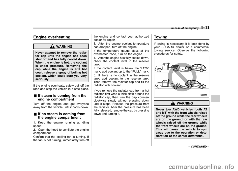
down and turning it. Towing
If towing is necessary, it is best done by
your SUBARU dealer or a commercial
towing service. Observe the following
procedures for safety.
WARNING
Never tow AWD vehicles (both AT
and MT) with the front wheels raised
off the ground while the rear wheels
are on the ground, or with the rear
wheels raised off the ground while
the front wheels are on the ground.
This will cause the vehicle to spin
away due to the operation or dete-
rioration of the center differential. In case of emergency
9-11
– CONTINUED –
Page 277 of 364

Maintenance schedule....................................... 11-3
Maintenance precautions ................................... 11-3
Before checking or servicing in the engine compartment .................................................... 11-4
When you do checking or servicing in the engine compartment while the engine is running .......... 11-4
Engine hood ....................................................... 11-4
Engine compartment overview .......................... 11-6
Non-turbo models .............................................. 11-6
Turbo models ..................................................... 11-7
Engine oil ............................................................ 11-8
Checking the oil level ......................................... 11-8
Changing the oil and oil filter .............................. 11-9
Recommended grade and viscosity .................. 11-11
Recommended grade and viscosity under severe driving conditions .......................................... 11-12
Synthetic oil ..................................................... 11-12
Cooling system ................................................ 11-12
Cooling fan, hose and connections ................... 11-12
Engine coolant ................................................. 11-13
Air cleaner element .......................................... 11-15
Replacing the air cleaner element ..................... 11-15
Spark plugs ...................................................... 11-17
Recommended spark plugs .............................. 11-18
Drive belts ........................................................ 11-18
Manual transmission oil .................................. 11-19
Checking the oil level ....................................... 11-19
Recommended grade and viscosity .................. 11-20
Automatic transmission fluid .......................... 11-20
Checking the fluid level .................................... 11-20 Recommended fluid
......................................... 11-21
Front differential gear oil (AT vehicles) .......... 11-21
Checking the oil level ...................................... 11-21
Recommended grade and viscosity .................. 11-22
Rear differential gear oil .................................. 11-22
Checking the gear oil level ............................... 11-22
Recommended grade and viscosity .................. 11-23
Power steering fluid ........................................ 11-24
Checking the fluid level .................................... 11-24
Recommended fluid ......................................... 11-25
Brake fluid ........................................................ 11-25
Checking the fluid level .................................... 11-25
Recommended brake fluid ............................... 11-26
Clutch fluid (MT vehicles) ............................... 11-26
Checking the fluid level .................................... 11-26
Recommended clutch fluid ............................... 11-27
Brake booster .................................................. 11-27
Brake pedal ...................................................... 11-27
Checking the brake pedal free play .................. 11-27
Checking the brake pedal reserve distance....... 11-28
Clutch pedal (MT vehicles) .............................. 11-28
Checking the clutch function ............................ 11-28
Checking the clutch pedal free play .................. 11-28
Replacement of brake pad and lining ............ 11-29
Breaking-in of new brake pads and linings ....... 11-29
Parking brake stroke ....................................... 11-30
Tires and wheels .............................................. 11-30
Types of tires ................................................... 11-30
Tire inspection ................................................. 11-30
Tire pressures and wear .................................. 11-31
Maintenance and service
11
Page 280 of 364
11-4Maintenance and service
guard against getting oil or fluids
in your eyes. If something does
get in your eyes, thoroughly
wash them out with clean water.
. Do not tamper with the wiring of
the SRS airbag system or seat-
belt pretensioner system, or at-
tempt to take its connectors
apart, as that may activate the
system or it can render it inop-
erative. The wiring and connec-
tors of these systems are yellow
for easy identification. NEVER
use a circuit tester for thesewiring.
If your SRS airbag or seatbelt
pretensioner needs service, con-
sult your nearest SUBARU deal-
er.
& Before checking or servicing
in the engine compartment
WARNING
. Always stop the engine and set
the parking brake firmly to pre-
vent the vehicle from moving.
. Always let the engine cool down.
Engine parts become very hot
when the engine is running and remain hot for some time after
the engine is stopped.
. Do not spill engine oil, engine
coolant, brake fluid or any other
fluid on hot engine components.
This may cause a fire.
. Always remove the key from the
ignition switch. When the ignition
switch is in the “ON ”position,
thecoolingfanmayoperate
suddenly even when the engine
is stopped.
& When you do checking or
servicing in the engine com-
partment while the engine isrunning
WARNING
A running engine can be dangerous.
Keep your fingers, hands, clothing,
hair and tools away from the cooling
fan, belts and any other moving
engine parts. Removing rings,
watches and ties is advisable. Engine hood
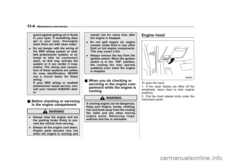
To open the hood:
1. If the wiper blades are lifted off the
windshield, return them to their originalpositions.
2. Pull the hood release knob under the
instrument panel.