fuse SUBARU IMPREZA WRX 2007 3.G Owners Manual
[x] Cancel search | Manufacturer: SUBARU, Model Year: 2007, Model line: IMPREZA WRX, Model: SUBARU IMPREZA WRX 2007 3.GPages: 364, PDF Size: 11.91 MB
Page 16 of 364

14 &Instrument panel
1) Door locks (page 2-4)
2) Outside mirror switch (page 3-33)
3) Light control lever (page 3-22)
4) Combination meter (page 3-6)
5) Wiper control lever (page 3-26)
6) Hazard warning flasher switch (page 3-6)
7) Audio (page 5-1)
8) Gear shift lever (5MT) (page 7-11)/
Gear shift lever (6MT) (page 7-9)/
Selector lever (AT) (page 7-15)
9) Climate control (page 4-1)
10) Cruise control (page 7-26)
11) Horn (page 3-35)
12) SRS airbag (page 1-35)
13) Tilt steering (page 3-35)
14) Fuse box (page 11-42)
15) Hood lock release knob (page 11-4)
16) Power windows (page 2-18)
Page 87 of 364

2-4Keys and doors
&Security indicator light
The security indicator light deters potential
thieves by indicating that the vehicle is
equipped with an immobilizer system. It
begins flashing (approximately once every
3 seconds) approximately 60 seconds
after the ignition switch is turned from the“ON ”position to the “Acc ”or “LOCK ”
position or immediately after the key is
pulled out.
If the security indicator light does not flash,
the immobilizer system may be faulty. If
this occurs, we recommend that you
contact your SUBARU dealer as soon aspossible.
In case an unauthorized key is used (e.g.
an imitation key), the security indicator
light comes on. NOTE
Even if the security indicator light
flashes irregularly or its fuse blows
(the light does not flash if its fuse is
blown), the immobilizer system will
function normally. &
Key replacement
Your key number plate and security ID
plate will be required if you ever need a
replacement key made. Any new key must
be registered for use with your vehicle ’s
immobilizer system before it can be used.
Up to four keys can be registered for use
with one vehicle.
For security, all the keys registered with
your vehicle ’s immobilizer system will
have their ID codes erased and re-
registered when a new key is made.
Therefore, all of your vehicle ’s keys must
be presented when a new key is regis-
tered. Any key that is not re-registered
when a new key is made cannot be used
after the other keys are re-registered. For
information on replacement keys and on
the registration of keys with your immo-
bilizer system, contact your SUBARU
dealer. Door locks &
Locking and unlocking from
the outside
To lock the driver ’s door from the outside
with the key, turn the key toward the rear.
To unlock the door, turn the key toward thefront.
Pull the outside door handle to open an
unlocked door.
Page 116 of 364

&Speedometer
The speedometer shows the vehicle speed. & Odometer/Trip meter
1) Trip meter
2) Odometer
This meter displays the odometer and two
trip meters when the ignition switch is inthe “LOCK ”, “Acc ”or “ON ”position.
If you press the trip knob when the ignition
switch is in the “LOCK ”position, the
odometer/trip meter will light up. It is
possible to switch between the A trip
meter and B trip meter indications while
the odometer/trip meter is lit up. If you do
not press the trip knob within 10 seconds
of illumination of the odometer/trip meter, the odometer/trip meter will go off. !
Odometer
The odometer shows the total distance
that the vehicle has been driven. ! Double trip meter
The trip meter shows the distance that the
vehicle has been driven since you last set
it to zero.
To change the mode indication, briefly
push the knob.
Each press of the knob changes the
function alternately.
To set the trip meter to zero, select the A
trip or B trip meter by pushing the knob
and keep the knob pushed for more than 2 seconds.
CAUTION
To ensure safety, do not attempt to
change the function of the indicator
during driving, as an accident couldresult.
NOTE
If the connection between the combina-
tion meter and battery is broken for any
reason such as vehicle maintenance or
fuse replacement, the data recorded on
the trip meter will be lost. & Tachometer
The tachometer shows the engine speed
in thousands of revolutions per minute.
CAUTION
Do not operate the engine with the
pointer of the tachometer in the red
zone. In this range, fuel injection will
be cut by the engine control module
to protect the engine from overrev-
ving. The engine will resume run-
ning normally after the engine speed
is reduced below the red zone. Instruments and controls
3-7
– CONTINUED –
Page 121 of 364

3-12Instruments and controls
To set the trip meter to zero, select the A
trip or B trip meter by pushing the knob
and keep the knob pushed for more than 2seconds.
CAUTION
To ensure safety, do not attempt to
change the function of the indicator
during driving, as an accident couldresult.
NOTE
If the connection between the combina-
tion meter and battery is broken for any
reason such as vehicle maintenance or
fuse replacement, the data recorded on
the trip meter will be lost. & Tachometer
The tachometer shows the engine speed
in thousands of revolutions per minute.
CAUTION
Do not operate the engine with the
pointer of the tachometer in the red
zone. In this range, fuel injection will
be cut by the engine control module
to protect the engine from overrev-
ving. The engine will resume run-
ning normally after the engine speed is reduced below the red zone.
& Fuel gauge
1) Low fuel warning light
The fuel gauge shows the approximate
amount of fuel remaining in the tank.
The gauge does not return to “E ” even
though the ignition switch is in the “Acc ”or
“ LOCK ”position.
The gauge may move slightly during
braking, turning or acceleration due to fuel
level movement in the tank. NOTE
You will see the
“FUEL DOOR”
sign in the fuel gauge.
This indicates that the fuel filler door
(lid) is located on the right side of thevehicle. ! Low fuel warning light
The low fuel warning light comes on when
the tank is nearly empty [approximately
2.3 US gal (9.0 liters, 1.9 Imp gal]. It only
operates when the ignition switch is in the“ ON ”position.
NOTE
This light does not go out unless the
tank is replenished up to an internal
Page 204 of 364

Starting the engine
CAUTION
Do not operate the starter motor
continuously for more than 10 sec-
onds. If the engine fails to start after
operating the starter for 5 to 10
seconds, wait for 10 seconds or
more before trying again.
& Manual transmission vehicle
1. Apply the parking brake.
2. Turn off unnecessary lights and ac- cessories.
3. Press the clutch pedal to the floor and
shift the shift lever into neutral. Hold the
clutch pedal to the floor while starting theengine.
The starter motor will only operate when
the clutch pedal is pressed fully to the
floor.
4. Turn the ignition switch to the “ON ”
position and check the operation of the
warning and indicator lights. Refer to the“ Warning and indicator lights ”section
(chapter 3).
5. Turn the ignition switch to the “START ”
position without depressing the accelera-
tor pedal. Release the key immediately after the engine has started.
If the engine does not start, try the following.
(1) Turn the ignition switch to the“OFF ”position and wait for at least
10 seconds. After checking that the
parking brake is firmly set, turn the
ignition switch to the “START ”position
while depressing the accelerator pedal
slightly (approximately a quarter of the
full stroke). Release the accelerator
pedal as soon as the engine starts.
(2) If this fails to start the engine, turn
the ignition switch back to the “OFF ”
position and wait for at least 10
seconds. Then fully depress the accel-
erator pedal and turn the ignition
switch to the “START ”position. If the
engine starts, quickly release the
accelerator pedal.
(3) If this fails to start the engine, turn
the ignition switch again to the “OFF ”
position. After waiting for 10 seconds
or longer, turn the ignition switch to the“ START ”position without depressing
the accelerator pedal.
(4) If the engine still refuses to start,
contact your nearest SUBARU dealer
for assistance.
6. Confirm that all warning and indicator
lights have gone off after the engine has
started. The fuel injection system auto- matically lowers the idle speed as the
engine warms up.
NOTE
The engine may be difficult to start
when the battery has been discon-
nected and reconnected (for mainte-
nance or other purposes). This diffi-
culty is caused by the electronically
controlled throttle ’s self-diagnosis
function. To overcome it, keep the
ignition switch in the “ON ”position
for approximately 10 seconds before
starting the engine. & Automatic transmission ve- hicle
1. Apply the parking brake.
2. Turn off unnecessary lights and ac- cessories.
3. Shift the selector lever to the “P ”or “N ”
position (preferably “P ”position).
The starter motor will only operate when
the selector lever is at the “P ” or “N ”
position.
4. Turn the ignition switch to the “ON ”
position and check the operation of the
warning and indicator lights. Refer to the“ Warning and indicator lights ”section
(chapter 3).
5. Turn the ignition switch to the “START ”
Starting and operating
7-7
– CONTINUED –
Page 205 of 364

7-8Starting and operating
position without depressing the accelera-
tor pedal. Release the key immediately
after the engine has started.
If the engine does not start, try the following.
(1) Turn the ignition switch to the“OFF ”position and wait for at least
10 seconds. After checking that the
parking brake is firmly set, turn the
ignition switch to the “START ”position
while depressing the accelerator pedal
slightly (approximately a quarter of the
full stroke). Release the accelerator
pedal as soon as the engine starts.
(2) If this fails to start the engine, turn
the ignition switch back to the “OFF ”
position and wait for at least 10
seconds. Then fully depress the accel-
erator pedal and turn the ignition
switch to the “START ”position. If the
engine starts, quickly release the
accelerator pedal.
(3) If this fails to start the engine, turn
the ignition switch again to the “OFF ”
position. After waiting for 10 seconds
or longer, turn the ignition switch to the“ START ”position without depressing
the accelerator pedal.
(4) If the engine still refuses to start,
contact your nearest SUBARU dealer
for assistance. 6. Confirm that all warning and indicator
lights have gone out after the engine has
started. The fuel injection system auto-
matically lowers the idle speed as the
engine warms up.
While the engine is warming up, make
sure that the selector lever is at the
“P ”or
“ N ”position and that the parking brake is
applied.
NOTE
The engine may be difficult to start
when the battery has been discon-
nected and reconnected (for mainte-
nance or other purposes). This diffi-
culty is caused by the electronically
controlled throttle ’s self-diagnosis
function. To overcome it, keep the
ignition switch in the “ON ”position
for approximately 10 seconds before
starting the engine.
CAUTION
If you restart the engine while the
vehicle is moving, shift the selector
lever into the “N ” position. Do not
attempt to place the selector lever of
a moving vehicle into the “P ” posi-
tion. Stopping the engine
The ignition switch should be turned off
only when the vehicle is stopped and the
engine is idling.
WARNING
Do not stop the engine when the
vehicle is moving. This will cause
loss of power to the power steering
and the brake booster, making steer-
ing and braking more difficult. It
could also result in accidental acti-
vation of the “LOCK ”position on the
ignition switch, causing the steering
wheel to lock.
Page 257 of 364

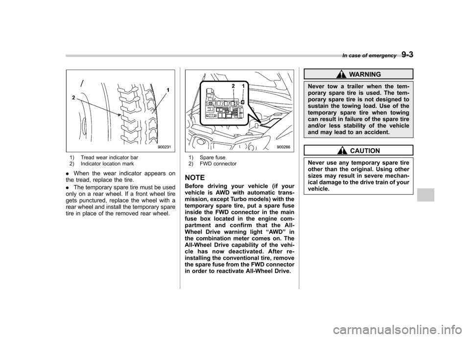
1) Tread wear indicator bar
2) Indicator location mark
. When the wear indicator appears on
the tread, replace the tire. . The temporary spare tire must be used
only on a rear wheel. If a front wheel tire
gets punctured, replace the wheel with a
rear wheel and install the temporary spare
tire in place of the removed rear wheel.1) Spare fuse
2) FWD connector
NOTE
Before driving your vehicle (if your
vehicle is AWD with automatic trans-
mission, except Turbo models) with the
temporary spare tire, put a spare fuse
inside the FWD connector in the main
fuse box located in the engine com-
partment and confirm that the All-
Wheel Drive warning light “AWD ”in
the combination meter comes on. The
All-Wheel Drive capability of the vehi-
cle has now deactivated. After re-
installing the conventional tire, remove
the spare fuse from the FWD connector
in order to reactivate All-Wheel Drive.
WARNING
Never tow a trailer when the tem-
porary spare tire is used. The tem-
porary spare tire is not designed to
sustain the towing load. Use of the
temporary spare tire when towing
can result in failure of the spare tire
and/or less stability of the vehicle
and may lead to an accident.
CAUTION
Never use any temporary spare tire
other than the original. Using other
sizes may result in severe mechan-
ical damage to the drive train of yourvehicle. In case of emergency
9-3
Page 278 of 364

Maintenance and serviceWheel balance .................................................. 11-33
Wear indicators ................................................ 11-33
Tire rotation direction mark .............................. 11-33
Tire rotation ..................................................... 11-34
Tire replacement .............................................. 11-34
Wheel replacement ........................................... 11-35
Aluminum wheels ............................................. 11-35
Intercooler water spray (WRX-STI) .................. 11-36
Windshield washer fluid .................................. 11-36
Replacement of wiper blades .......................... 11-38
Windshield wiper blade assembly ..................... 11-38
Windshield wiper blade rubber ......................... 11-38
Rear window wiper blade assembly .................. 11-39
Rear window wiper blade rubber ....................... 11-40
Battery. .............................................................. 11-41 Fuses
................................................................ 11-42
Main fuse .......................................................... 11-44
Installation of accessories .............................. 11-44
Replacing bulbs ............................................... 11-45
Headlights (WRX-STI) ....................................... 11-46
Headlights (Except WRX-STI) ........................... 11-47
Front turn signal light bulbs ............................. 11-49
Parking light .................................................... 11-49
Front fog light .................................................. 11-49
Rear combination lights ................................... 11-49
License plate light ........................................... 11-51
Dome light, map light and cargo area light ....... 11-51
Trunk light ....................................................... 11-52
High mount stop light ...................................... 11-52
Other bulbs ..................................................... 11-53
Page 282 of 364

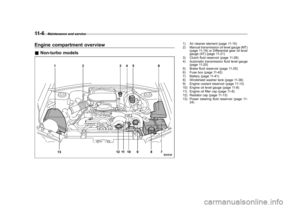
11-6Maintenance and service
Engine compartment overview &Non-turbo models1) Air cleaner element (page 11-15)
2) Manual transmission oil level gauge (MT)
(page 11-19) or Differential gear oil level
gauge (AT) (page 11-21)
3) Clutch fluid reservoir (page 11-26)
4) Automatic transmission fluid level gauge (page 11-20)
5) Brake fluid reservoir (page 11-25)
6) Fuse box (page 11-42)
7) Battery (page 11-41)
8) Windshield washer tank (page 11-36)
9) Engine coolant reservoir (page 11-13)
10) Engine oil level gauge (page 11-8)
11) Engine oil filler cap (page 11-8)
12) Radiator cap (page 11-13)
13) Power steering fluid reservoir (page 11- 24)
Page 283 of 364

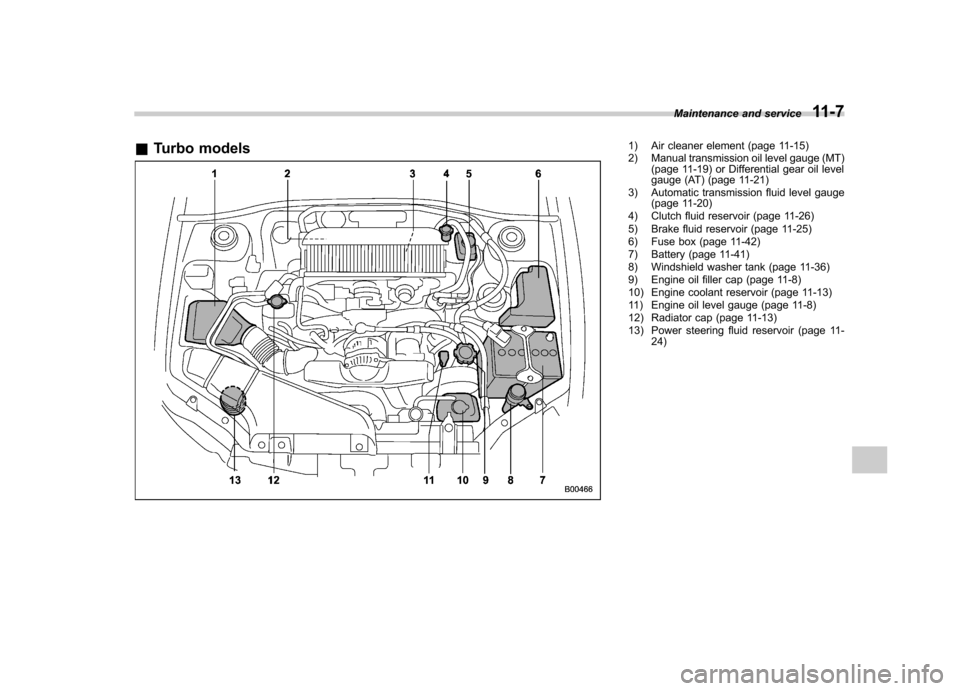
&Turbo models1) Air cleaner element (page 11-15)
2) Manual transmission oil level gauge (MT)
(page 11-19) or Differential gear oil level
gauge (AT) (page 11-21)
3) Automatic transmission fluid level gauge (page 11-20)
4) Clutch fluid reservoir (page 11-26)
5) Brake fluid reservoir (page 11-25)
6) Fuse box (page 11-42)
7) Battery (page 11-41)
8) Windshield washer tank (page 11-36)
9) Engine oil filler cap (page 11-8)
10) Engine coolant reservoir (page 11-13)
11) Engine oil level gauge (page 11-8)
12) Radiator cap (page 11-13)
13) Power steering fluid reservoir (page 11- 24)Maintenance and service
11-7