radio SUBARU IMPREZA WRX 2007 3.G Owners Manual
[x] Cancel search | Manufacturer: SUBARU, Model Year: 2007, Model line: IMPREZA WRX, Model: SUBARU IMPREZA WRX 2007 3.GPages: 364, PDF Size: 11.91 MB
Page 82 of 364
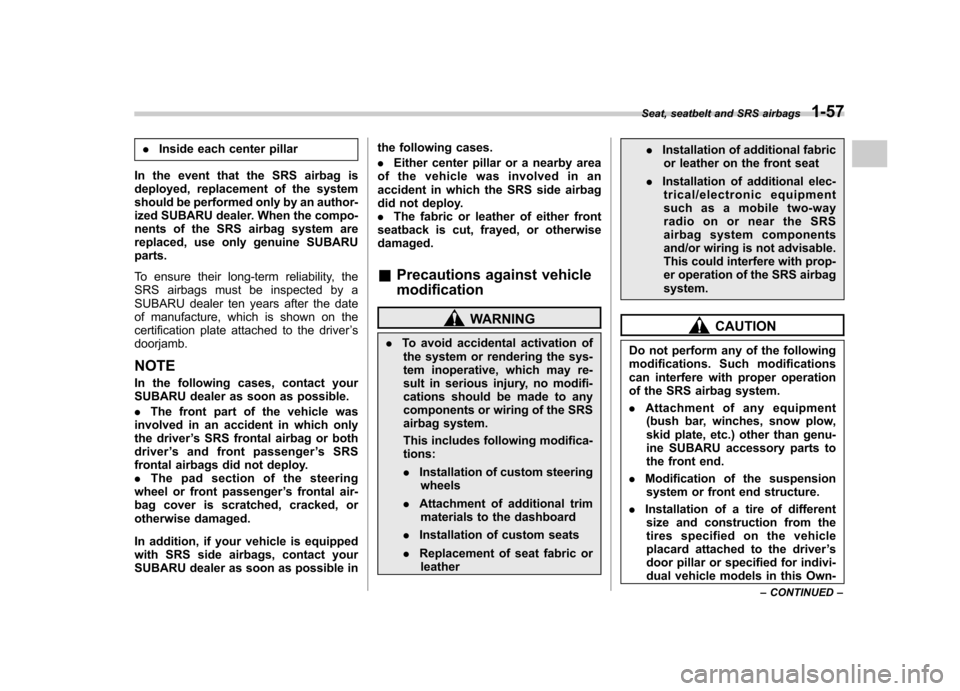
.Inside each center pillar
In the event that the SRS airbag is
deployed, replacement of the system
should be performed only by an author-
ized SUBARU dealer. When the compo-
nents of the SRS airbag system are
replaced, use only genuine SUBARUparts.
To ensure their long-term reliability, the
SRS airbags must be inspected by a
SUBARU dealer ten years after the date
of manufacture, which is shown on the
certification plate attached to the driver ’s
doorjamb. NOTE
In the following cases, contact your
SUBARU dealer as soon as possible. . The front part of the vehicle was
involved in an accident in which only
the driver ’s SRS frontal airbag or both
driver ’s and front passenger ’sSRS
frontal airbags did not deploy.. The pad section of the steering
wheel or front passenger ’s frontal air-
bag cover is scratched, cracked, or
otherwise damaged.
In addition, if your vehicle is equipped
with SRS side airbags, contact your
SUBARU dealer as soon as possible in the following cases. .
Either center pillar or a nearby area
of the vehicle was involved in an
accident in which the SRS side airbag
did not deploy.. The fabric or leather of either front
seatback is cut, frayed, or otherwisedamaged.
& Precautions against vehicle modification
WARNING
. To avoid accidental activation of
the system or rendering the sys-
tem inoperative, which may re-
sult in serious injury, no modifi-
cations should be made to any
components or wiring of the SRS
airbag system.
This includes following modifica- tions: . Installation of custom steering
wheels
. Attachment of additional trim
materials to the dashboard
. Installation of custom seats
. Replacement of seat fabric or
leather .
Installation of additional fabric
or leather on the front seat
. Installation of additional elec-
trical/electronic equipment
such as a mobile two-way
radioonorneartheSRS
airbag system components
and/or wiring is not advisable.
This could interfere with prop-
er operation of the SRS airbagsystem.CAUTION
Do not perform any of the following
modifications. Such modifications
can interfere with proper operation
of the SRS airbag system. . Attachment of any equipment
(bush bar, winches, snow plow,
skid plate, etc.) other than genu-
ine SUBARU accessory parts to
the front end.
. Modification of the suspension
system or front end structure.
. Installation of a tire of different
size and construction from the
tires specified on the vehicle
placard attached to the driver ’s
door pillar or specified for indivi-
dual vehicle models in this Own-
Seat, seatbelt and SRS airbags
1-57
– CONTINUED –
Page 90 of 364

Remote keyless entry system
Two transmitters are provided for your vehicle.
The remote keyless entry system has the
following functions. .Locking and unlocking the doors (and
rear gate on the Wagon) without a key. Sounding a panic alarm
. Arming and disarming the alarm sys-
tem. See the next section “Alarm system ”
for detailed information.
This device complies with Part 15 of
the FCC Rules and with RSS-210 of
Industry Canada. Operation is subject
to the following two conditions: (1) This
device may not cause harmful inter-
ference, and (2) this device must
accept any interference received, in-
cluding interference that may cause
undesired operation.
Changes or modifications not ex-
pressly approved by the party respon-
sible for compliance could void theuser ’s authority to operate the equip-
ment.
The operable distance of the keyless entry
system is approximately 30 feet (10
meters). However, this distance will vary
depending on environmental conditions. The system
’s operable distance will be
shorter in areas near a facility or electronic
equipment emitting strong radio waves
such as a power plant, broadcast station,
TV tower, or remote controller of home
electronic appliances.
The remote keyless entry system does not
operate when the key is inserted in the
ignition switch to prevent accidental lock-out.
CAUTION
. Do not expose the transmitter to
severe shocks, such as those
experienced as a result of drop-
ping or throwing.
. Do not take the transmitter apart
except when replacing the bat-
tery.
. Do not get the transmitter wet. If it
gets wet, wipe it dry with a cloth
immediately.
: LOCK/ARM button Press to Lock all doors.
Press and Hold to activate panic alarm.
Press 3 times in a 5-second period to
use vehicle finder function.
: UNLOCK/DISARM button1) Press once to Unlock driver ’s door.
2) Press a second time to Unlock all
other doors (and rear gate on the
Wagon).
& Locking the doors
Briefly press the “
”button (for less than 2
seconds) to lock all doors (and rear gate
on the Wagon).
An electronic chirp will sound once and
the turn signal lights will flash once.
If any of the doors (or the rear gate) is not Keys and doors
2-7
– CONTINUED –
Page 113 of 364
3-4Instruments and controls
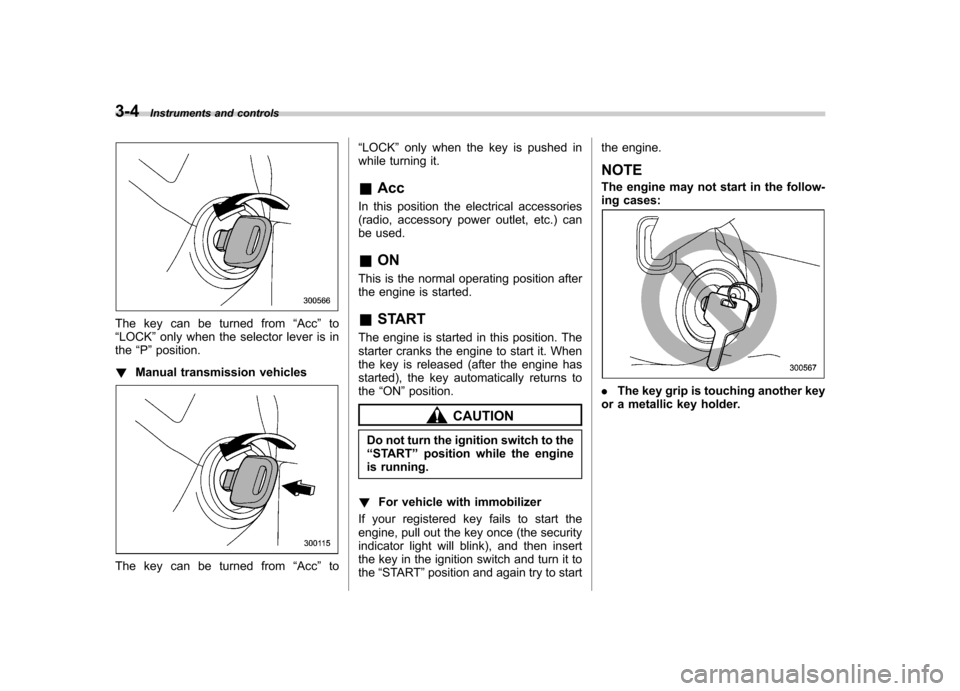
The key can be turned from “Acc ”to
“ LOCK ”only when the selector lever is in
the “P ”position.
! Manual transmission vehicles
The key can be turned from “Acc ”to “
LOCK ”only when the key is pushed in
while turning it.
& Acc
In this position the electrical accessories
(radio, accessory power outlet, etc.) can
be used. & ON
This is the normal operating position after
the engine is started. & START
The engine is started in this position. The
starter cranks the engine to start it. When
the key is released (after the engine has
started), the key automatically returns tothe “ON ”position.
CAUTION
Do not turn the ignition switch to the “ START ”position while the engine
is running.
! For vehicle with immobilizer
If your registered key fails to start the
engine, pull out the key once (the security
indicator light will blink), and then insert
the key in the ignition switch and turn it tothe “START ”position and again try to start the engine.
NOTE
The engine may not start in the follow-
ing cases:
. The key grip is touching another key
or a metallic key holder.
Page 131 of 364
3-22Instruments and controls
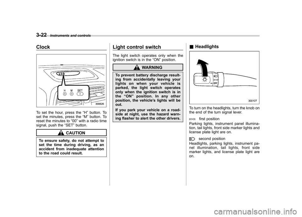
Clock
To set the hour, press the “H ” button. To
set the minutes, press the “M ”button. To
reset the minutes to “00 ”with a radio time
signal, push the “SET ”button.
CAUTION
To ensure safety, do not attempt to
set the time during driving, as an
accident from inadequate attention
to the road could result. Light control switch
The light switch operates only when the
ignition switch is in the
“ON ”position.
WARNING
To prevent battery discharge result-
ing from accidentally leaving your
lights on when your vehicle is
parked, the light switch operates
only when the ignition switch is inthe “ON ”position. In any other
position, the vehicle ’s lights will be
out.
If you park your vehicle on a road-
side at night, use the hazard warn-
ing flasher to alert the other drivers. &
Headlights
To turn on the headlights, turn the knob on
the end of the turn signal lever.
first position
Parking lights, instrument panel illumina-
tion, tail lights, front side marker lights and
license plate light are on.
second position
Headlights, parking lights, instrument pa-
nel illumination, tail lights, front side
marker lights, and license plate light areon.
Page 159 of 364
Antenna system.................................................. 5-2
Printed antenna ................................................... 5-2
FM reception ....................................................... 5-2
Installation of accessories .................................. 5-2
Audio set ............................................................. 5-3
Type A audio set ................................................. 5-3
Type B audio set ................................................. 5-3
In-dash 6 CD auto changer (Optional audio unit –
if equipped) ....................................................... 5-3
Type A audio set (if equipped) ........................... 5-4
Radio operation. .................................................. 5-4 Compact disc player operation .
............................ 5-7
CD changer control (if optional in-dash CD changer is connected) ....................................... 5-9
Type B audio set (if equipped) .......................... 5-11
Radio operation ................................................. 5-11
Built-in CD changer control ................................ 5-15
Auxiliary unit operation ...................................... 5-20
In-dash 6 CD auto changer (if equipped) ......... 5-23
Loading and unloading compact discs ............... 5-23
Precautions to observe when handling a compact disc ................................................... 5-25 Audio
5
Page 160 of 364
5-2Audio
Antenna system &Printed antenna
CAUTION
Do not use sharp instruments or
window cleaner containing abra-
sives to clean the inner surface of
the window on which the antenna is
printed. Doing so may damage the
antenna printed on the window.
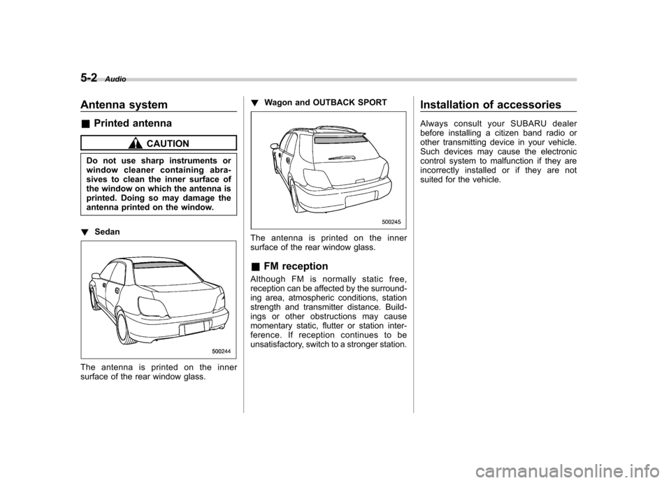
! Sedan
The antenna is printed on the inner
surface of the rear window glass. !
Wagon and OUTBACK SPORT
The antenna is printed on the inner
surface of the rear window glass. &FM reception
Although FM is normally static free,
reception can be affected by the surround-
ing area, atmospheric conditions, station
strength and transmitter distance. Build-
ings or other obstructions may cause
momentary static, flutter or station inter-
ference. If reception continues to be
unsatisfactory, switch to a stronger station. Installation of accessories
Always consult your SUBARU dealer
before installing a citizen band radio or
other transmitting device in your vehicle.
Such devices may cause the electronic
control system to malfunction if they are
incorrectly installed or if they are not
suited for the vehicle.
Page 161 of 364

Audio set
Your SUBARU may be equipped with one
of the following audio sets. See the pages
indicated in this section for operatingdetails. &Type A audio set
.Radio operation: refer to page 5-4
. Compact disc player operation: refer to
page 5-7 . CD changer control: refer to page 5-9 &
Type B audio set
.Radio operation: refer to page 5-11
. Built-in CD changer control: refer to
page 5-15 . Auxiliary unit operation: refer to page 5-
20 &
In-dash 6 CD auto changer
(Optional audio unit –if
equipped)
. Loading and unloading compact discs:
refer to page 5-23 Audio
5-3
Page 162 of 364
5-4Audio
Type A audio set (if equipped)
The audio set will operate only when the ignition switch is in the “Acc ”or “ON ”position.
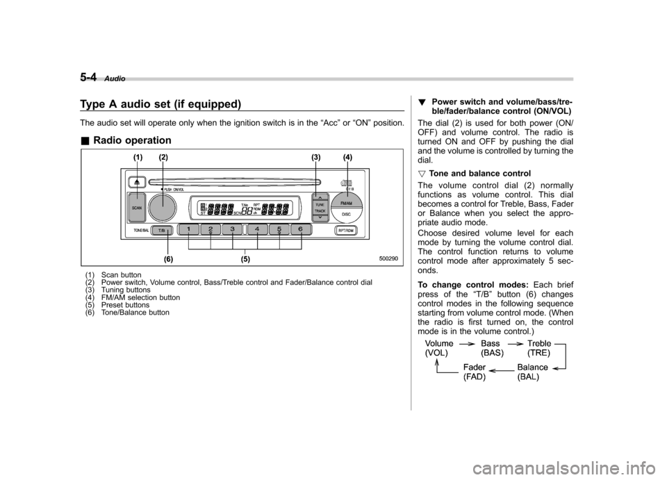
& Radio operation
(1) Scan button
(2) Power switch, Volume control, Bass/Treble control and Fader/Balance control dial
(3) Tuning buttons
(4) FM/AM selection button
(5) Preset buttons
(6) Tone/Balance button !
Power switch and volume/bass/tre-
ble/fader/balance control (ON/VOL)
The dial (2) is used for both power (ON/
OFF) and volume control. The radio is
turned ON and OFF by pushing the dial
and the volume is controlled by turning thedial. ! Tone and balance control
The volume control dial (2) normally
functions as volume control. This dial
becomes a control for Treble, Bass, Fader
or Balance when you select the appro-
priate audio mode.
Choose desired volume level for each
mode by turning the volume control dial.
The control function returns to volume
control mode after approximately 5 sec-onds.
To change control modes: Each brief
press of the “T/B ”button (6) changes
control modes in the following sequence
starting from volume control mode. (When
the radio is first turned on, the control
mode is in the volume control.)
Page 163 of 364

Display Control mode
Turn counterclockwise Turn clockwise
BAS Bass control For less bass sound For more bass sound
TRE Treble control For less treble sound For more treble sound
BAL Balance control To increase left speaker volume and de-
crease right speaker volume To increase right speaker volume and
decrease left speaker volume
FA D Fader control
To increase rear speaker volume and
decrease front speaker volume To increase front speaker volume and
decrease rear speaker volume
VOL Volume control For less volume For more volume
! FM/AM selection button (FM/AM)
Push the “FM/AM ”button (4) when the
radio is off to turn on the radio.
Push the “FM/AM ”button when the radio
is on to select FM1, FM2 or AM reception.
Each time this button is pressed, the band
will change in the following order:
The display indicates which one is cur-
rently selected. !
Stereo indicator
The stereo indicator “ST ”will come on
when an FM stereo broadcast is received. Audio
5-5
– CONTINUED –
Page 164 of 364
5-6Audio
! Manual tuning (TUNE)
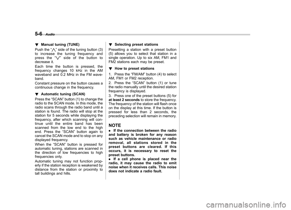
Push the “
”side of the tuning button (3)
to increase the tuning frequency and
press the “
”sideofthebuttonto
decrease it.
Each time the button is pressed, the
frequency changes 10 kHz in the AM
waveband and 0.2 MHz in the FM wave-band.
Constant pressure on the button causes a
continuous change in the frequency. ! Automatic tuning (SCAN)
Press the “SCAN ”button (1) to change the
radio to the SCAN mode. In this mode, the
radio scans through the radio band until a
station is found. The radio will stop at the
station for 5 seconds while displaying the
frequency, after which scanning will con-
tinue until the entire band has been
scanned from the low end to the high
end. Press the “SCAN ”button again to
cancel the SCAN mode and to stop on any
displayed frequency.
When the “SCAN ”button is pressed for
automatic tuning, stations are scanned in
the direction of low frequencies to high
frequencies only.
Automatic tuning may not function prop-
erly if the station reception is weakened by
distance from the station or proximity to
tall buildings and hills. !
Selecting preset stations
Presetting a station with a preset button
(5) allows you to select that station in a
single operation. Up to six AM, FM1 and
FM2 stations each may be preset. ! How to preset stations
1. Press the “FM/AM ”button (4) to select
AM, FM1 or FM2 reception.
2. Press the “SCAN ”button (1) or tune
the radio manually until the desired station
frequency is displayed.
3. Press one of the preset buttons (5) for
at least 2 seconds to store the frequency.
The frequency of the station will flash once
on the display at this time. If the button is
pressed for less than 2 seconds, the
preceding selection will remain in memory.
NOTE . If the connection between the radio
and battery is broken for any reason
such as vehicle maintenance or radio
removal, all stations stored in the
preset buttons are cleared. If this
occurs, it is necessary to reset the
preset buttons.. If a cell phone is placed near the
radio, it may cause the radio to emit
noise when it receives calls. This noise
does not indicate a radio fault.