steering wheel SUBARU IMPREZA WRX 2011 4.G User Guide
[x] Cancel search | Manufacturer: SUBARU, Model Year: 2011, Model line: IMPREZA WRX, Model: SUBARU IMPREZA WRX 2011 4.GPages: 458, PDF Size: 16.22 MB
Page 89 of 458
1-58Seat, seatbelt and SRS airbags
This includes following modifica- tions. .Installation of custom steering
wheels
. Attachment of additional trim
materials to the dashboard
. Installation of custom seats
. Replacement of seat fabric or
leather
. Installation of additional fabric or
leather on the front seat
. Attachment of a hands-free mi-
crophone or any other accessory
to a front pillar, a center pillar, a
rear pillar, the windshield, a side
window, an assist grip, or any
other cabin surface that would be
near a deploying SRS curtainairbag.
. Installation of additional electri-
cal/electronic equipment such as
a mobile two-way radio on or
near the SRS airbag system
components and/or wiring is not
advisable. This could interfere
with proper operation of the
SRS airbag system.CAUTION
Do not perform any of the following
modifications. Such modifications
can interfere with proper operation
of the SRS airbag system. . Attachment of any equipment
(bush bar, winches, snow plow,
skid plate, etc.) other than genu-
ine SUBARU accessory parts to
the front end.
. Modification of the suspension
system or front end structure.
. Installation of a tire of different
size and construction from the
tires specified on the vehicle
placard attached to the driver ’s
door pillar or specified for indivi-
dual vehicle models in this Own-er ’s Manual.
. Attachment of any equipment
(side steps or side sill protectors,
etc.) other than genuine SUBARU
accessory parts to the side body.
Always consult your SUBARU dealer if
you want to install any accessory parts on
your vehicle.
Page 121 of 458

Instruments and controlsCruise control set indicator light ......................... 3-27
Front fog light indicator light (if equipped) .......... 3-27
Headlight indicator light (if equipped) ................. 3-27
Driver ’s control center differential auto indicator
light (STI) ......................................................... 3-27
Driver ’s control center differential indicator and
warning lights (STI) .......................................... 3-27
REV indicator light (STI) ..................................... 3-28
Clock ................................................................... 3-28
Information display ............................................ 3-29
Outside temperature indicator ............................ 3-29
Current fuel consumption (if equipped) ............... 3-30
Average fuel consumption .................................. 3-30
Turn off display of fuel consumption indicator .......................................................... 3-31
Light control switch ........................................... 3-31
Headlights. ......................................................... 3-32
High/low beam change (dimmer) ......................... 3-32
Headlight flasher ................................................ 3-32 Daytime running light system
............................. 3-33
Turn signal lever ................................................ 3-33
Illumination brightness control ......................... 3-33
Headlight beam leveler (if equipped) ............... 3-34
Front fog light switch (if equipped) .................. 3-36
Wiper and washer .............................................. 3-36
Windshield wiper and washer switches .............. 3-38
Rear window wiper and washer switch –
5-door ............................................................. 3-39
Mirrors ................................................................ 3-40
Inside mirror ...................................................... 3-40
Auto-dimming mirror/compass (if equipped) ....... 3-40
Auto-dimming mirror/compass with HomeLink
®(if equipped) .................................................... 3-41
Outside mirrors ................................................. 3-47
Defogger and deicer .......................................... 3-48
Tilt/telescopic steering wheel ........................... 3-50
Horn .................................................................... 3-51
Page 122 of 458
Ignition switch
WARNING
. Never turn the ignition switch to
“ LOCK ”while the vehicle is
being driven or towed because
that will lock the steering wheel,
preventing steering control. And
when the engine is turned off, it
takes a much greater effort than
usual to steer.
. Before leaving the vehicle, al-
ways remove the key from the
ignition switch for safety and
never allow an unattended child
to remain in the vehicle. Failure
to follow this procedure could
result in injury to a child or
others. Children could operate
the power windows, the moon-
roof or other controls or even
make the vehicle move.
CAUTION
Do not attach a large key holder or
key case to either key. If it banged
against your knees or hands while
you are driving, it could turn the
ignition switch from the “ON ”posi- tion to the
“Acc ”or “LOCK ”posi-
tion, thereby stopping the engine.
Also, if the key is attached to a
keyholder or to a large bunch of
other keys, centrifugal force may act
on it as the vehicle moves, resulting
in unwanted turning of the ignitionswitch.
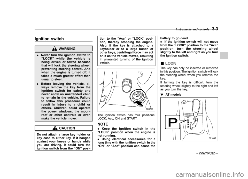
The ignition switch has four positions:
LOCK, Acc, ON and START. NOTE . Keep the ignition switch in the
“ LOCK ”position when the engine is
not running. . Using electrical accessories for a
long time with the ignition switch in the“ ON ”or “Acc ”position can cause the battery to go dead..
If the ignition switch will not move
from the “LOCK ”position to the “Acc ”
position, turn the steering wheel
slightly to the left and right as you turn
the ignition switch. & LOCK
The key can only be inserted or removed
in this position. The ignition switch will lock
the steering wheel when you remove the
key.
If turning the key is difficult, turn the
steering wheel slightly to the right and left
as you turn the key. ! AT models
Instruments and controls 3-3
– CONTINUED –
Page 169 of 458
3-50Instruments and controls
CAUTION
. To prevent the battery from being
discharged, do not operate the
defogger and deicer system con-
tinuously for any longer than
necessary.
. Do not use sharp instruments or
window cleaner containing abra-
sives to clean the inner surface
of the rear window. They may
damage the conductors printed
on the window.
NOTE . Turn on the defogger and deicer
system if the wipers are frozen to the windshield.. If the windshield is covered with
snow, remove the snow so that the
windshield wiper deicer works effec-
tively.. While the defogger and deicer sys-
tem is in the continuous operation
mode, if the vehicle speed remains at
9 mph (15 km/h) or less for 15 minutes,
the windshield wiper deicer automati-
cally stops operating, though the rear
window defogger and outside mirror
defogger maintain continuous opera-
tion in this condition. Tilt/telescopic steering wheel
WARNING
. Do not adjust the steering wheel
tilt/telescopic position while driv-
ing. This may cause loss of
vehicle control and result in
personal injury.
. If the lever cannot be raised to
the fixed position, adjust the
steering wheel again. It is dan-
gerous to drive without locking
the steering wheel. This may
cause loss of vehicle control
and result in personal injury.
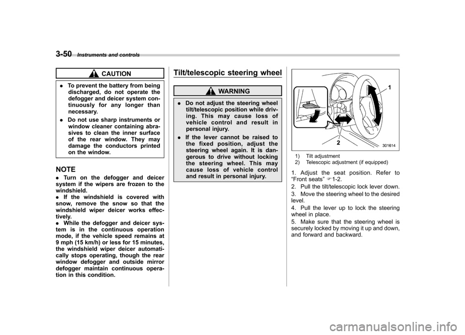
1) Tilt adjustment
2) Telescopic adjustment (if equipped)
1. Adjust the seat position. Refer to “ Front seats ”F 1-2.
2. Pull the tilt/telescopic lock lever down.
3. Move the steering wheel to the desired level.
4. Pull the lever up to lock the steering
wheel in place.
5. Make sure that the steering wheel is
securely locked by moving it up and down,
and forward and backward.
Page 229 of 458
5-42Audio
counterclockwise, the displayed category
changes in the opposite sequence.
To select the category, press the “TUNE/
TRACK/CH ”dial. To close the iPod®
menu, press the “LIST ”button for more
than 1.5 seconds. To return to the pre-
vious screen, briefly press the “LIST ”
button. & Display selection
Refer to “Display selection ”F 5-30.
! Page scroll
Refer to “Page (track/folder title) scroll ”
F 5-31.
& Folder selection (only when
connecting USB storage de- vice)
Refer to “Folder selection ”F 5-31. NOTE
When an iPod
®is connected, you
cannot select a folder. & When “CHECK DEVICE ”is
displayed
This message is displayed under the
following conditions. . When there is a short in the USB bus
. When a non-corresponding device (for
example a USB mouse) is connected. When a non-corresponding iPod
®is
connected . When a connected iPod
®is frozen
. When a transmission malfunction oc-
curs . When an iPod
®confirmation malfunc-
tion occurs. When a HUB class USB storage
device is connected
Disconnect the USB storage device/iPod
®
and check it. Audio control buttons (if
equipped)
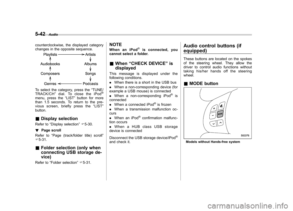
These buttons are located on the spokes
of the steering wheel. They allow the
driver to control audio functions without
taking his/her hands off the steeringwheel. &
MODE buttonModels without Hands-free system
Page 273 of 458
7-10Starting and operating
position and check the operation of the
warning and indicator lights. Refer to“Warning and indicator lights ”F 3-13.
5. Turn the ignition switch to the “START ”
position without depressing the accelera-
tor pedal. Release the key immediately
after the engine has started.
If the engine does not start, try the following.
(1) Turn the ignition switch to the“OFF ”position and wait for at least
10 seconds. After checking that the
parking brake is firmly set, turn the
ignition switch to the “START ”position
while depressing the accelerator pedal
slightly (approximately a quarter of the
full stroke). Release the accelerator
pedal as soon as the engine starts.
(2) If this fails to start the engine, turn
the ignition switch back to the “OFF ”
position and wait for at least 10
seconds. Then fully depress the accel-
erator pedal and turn the ignition
switch to the “START ”position. If the
engine starts, quickly release the
accelerator pedal.
(3) If this fails to start the engine, turn
the ignition switch again to the “OFF ”
position. After waiting for 10 seconds
or longer, turn the ignition switch to the“ START ”position without depressing
the accelerator pedal. (4) If the engine still refuses to start,
contact your nearest SUBARU dealer
for assistance.
6. Confirm that all warning and indicator
lights have turned off after the engine has
started. The fuel injection system auto-
matically lowers the idle speed as the
engine warms up.
While the engine is warming up, make
sure that the select lever is at the “P ” or
“ N ”position and that the parking brake is
applied.
CAUTION
If you restart the engine while the
vehicle is moving, shift the select
lever into the “N ” position. Do not
attempt to place the select lever of a
moving vehicle into the “P ” posi-
tion. Stopping the engine
The ignition switch should be turned off
only when the vehicle is stopped and the
engine is idling.
WARNING
Do not stop the engine when the
vehicle is moving. This will cause
loss of power to the power steering
and the brake booster, making steer-
ing and braking more difficult. It
could also result in accidental acti-
vation of the “LOCK ”position on the
ignition switch, causing the steering
wheel to lock.
Page 282 of 458
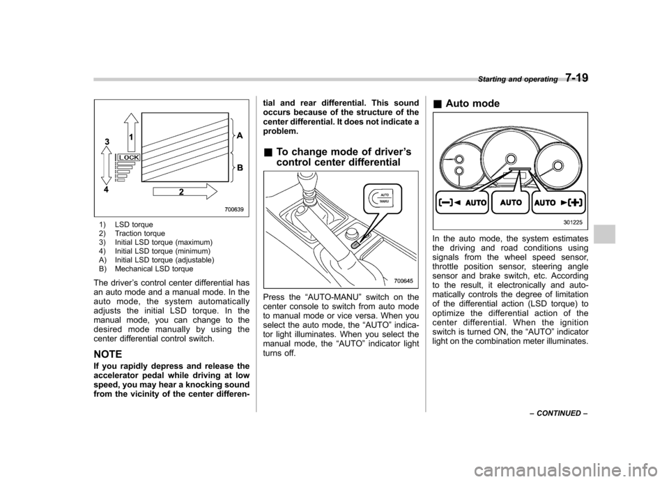
1) LSD torque
2) Traction torque
3) Initial LSD torque (maximum)
4) Initial LSD torque (minimum)
A) Initial LSD torque (adjustable)
B) Mechanical LSD torque
The driver ’s control center differential has
an auto mode and a manual mode. In the
auto mode, the system automatically
adjusts the initial LSD torque. In the
manual mode, you can change to the
desired mode manually by using the
center differential control switch. NOTE
If you rapidly depress and release the
accelerator pedal while driving at low
speed, you may hear a knocking sound
from the vicinity of the center differen- tial and rear differential. This sound
occurs because of the structure of the
center differential. It does not indicate aproblem.
& To change mode of driver ’s
control center differential
Press the “AUTO-MANU ”switch on the
center console to switch from auto mode
to manual mode or vice versa. When you
select the auto mode, the “AUTO ”indica-
tor light illuminates. When you select the
manual mode, the “AUTO ”indicator light
turns off. &
Auto mode
In the auto mode, the system estimates
the driving and road conditions using
signals from the wheel speed sensor,
throttle position sensor, steering angle
sensor and brake switch, etc. According
to the result, it electronically and auto-
matically controls the degree of limitation
of the differential action (LSD torque) to
optimize the differential action of the
center differential. When the ignition
switch is turned ON, the “AUTO ”indicator
light on the combination meter illuminates. Starting and operating
7-19
– CONTINUED –
Page 283 of 458
![SUBARU IMPREZA WRX 2011 4.G User Guide 7-20Starting and operating
The auto mode has 3 modes as follows.
Mode Operation
AUTO [+] This mode emphasizes traction control and strengthens the
limitation of differential action
that is suitable SUBARU IMPREZA WRX 2011 4.G User Guide 7-20Starting and operating
The auto mode has 3 modes as follows.
Mode Operation
AUTO [+] This mode emphasizes traction control and strengthens the
limitation of differential action
that is suitable](/img/17/7260/w960_7260-282.png)
7-20Starting and operating
The auto mode has 3 modes as follows.
Mode Operation
AUTO [+] This mode emphasizes traction control and strengthens the
limitation of differential action
that is suitable for driving on
slippery roads for vehicle stabi-
lity.
AUTO This mode is suitable for most driving situations.
AUTO [ �] This mode is suitable when you
seek quick response from the
steering wheel and smooth
driving.
! Mode setting method
In most situations, it is recommended that the “AUTO ”mode is selected.
Push the control switch forward to select the
“AUTO [+] ”mode. After setting the
mode, “
”on the combination meter
illuminates.
Pull the control switch rearward to select the “AUTO [ �]” mode. After setting the
mode, “
”on the combination meter
illuminates.
When the “AUTO [+] ”mode is selected,
pull the control switch rearward to change
to the “AUTO ”mode. When the “AUTO
[ � ]” mode is set, push the control switch
forward to change to the “AUTO ”mode. &
Manual mode
In the manual mode, you can use the
center differential control switch to adjust
the initial LSD torque as desired. When
this mode is selected, the “AUTO ”indica-
tor light on the combination meter turnsoff.
Page 290 of 458
Gear shifts can be performed by using the
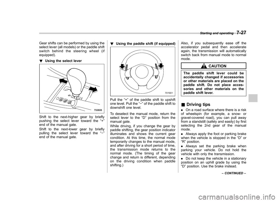
select lever (all models) or the paddle shift
switch behind the steering wheel (ifequipped). !Using the select lever
Shift to the next-higher gear by briefly
pushing the select lever toward the “+ ”
end of the manual gate.
Shift to the next-lower gear by briefly
pulling the select lever toward the “� ”
end of the manual gate. !
Using the paddle shift (if equipped)
Pull the “+ ” of the paddle shift to upshift
one level. Pull the “� ” of the paddle shift to
downshift one level.
To deselect the manual mode, return the
select lever to the “D ” position from the
manual gate.
While driving, if you change the gear by
paddle shifting, the gear position indicator
illuminates and shows the current gear
condition. At this time, the normal mode
temporarily changes to the manual mode,
and after driving for a short period of time,
the transmission mode returns to the
normal mode. (The timing of the gear
change and return is different, depending
on the driving condition when paddleshifting.) Also, if you subsequently ease off the
accelerator pedal and then accelerate
again, the transmission will automatically
switch back from manual mode to normalmode.
CAUTION
The paddle shift lever could be
accidentally changed if accessories
or other materials are placed on the
paddle shift. Do not place acces-
sories and other materials on the
paddle shift lever.
& Driving tips
. On a road surface where there is a risk
of wheelspin (for example, a snow- or
gravel-covered road), you can pull away
from a standstill (safely and easily) by first
selecting the 2nd gear of the manualmode. . Always apply the foot or parking brake
when the vehicle is stopped in the “D ”or
“ R ”position.
. Always set the parking brake when
parking your vehicle. Do not hold the
vehicle with only the transmission. . Do not keep the vehicle in a stationary
position on an uphill grade by using the “ D ”position. Use the brake instead. Starting and operating
7-27
– CONTINUED –
Page 294 of 458
Power steering
The power steering system operates only
when the engine is running.
If you lose power steering assist because
the engine stops or the system fails to
function, you can steer but it will take
much more effort.
CAUTION
Do not hold the steering wheel at the
fully locked position left or right for
more than 5 seconds. This may
damage the power steering pump.
NOTE
Right after the engine has been started
and before it has warmed up, you may
hear a noise coming from areas adja-
cent to the power steering pump which
is located at the right-front area of the
engine compartment. This noise is
normal. It does not indicate power
steering system trouble. Braking &
Braking tips
WARNING
Never rest your foot on the brake
pedal while driving. This can cause
dangerous overheating of the
brakes and needless wear on the
brake pads and linings.
! When the brakes get wet
When driving in rain or after washing the
vehicle, the brakes may get wet. As a
result, brake stopping distance will be
longer. To dry the brakes, drive the vehicle
at a safe speed while lightly depressing
the brake pedal to heat up the brakes. ! Use of engine braking
Remember to make use of engine braking
in addition to foot braking. When descend-
ing a grade, if only the foot brake is used,
the brakes may start working improperly
because of brake fluid overheating,
caused by overheated brake pads. To
help prevent this, shift into a lower gear to
get stronger engine braking. ! Braking when a tire is punctured
Do not depress the brake pedal suddenly
when a tire is punctured. This could cause a loss of control of the vehicle. Keep
driving straight ahead while gradually
reducing speed. Then slowly pull off the
road to a safe place. &
Brake system
! Two separate circuits
Your vehicle has two separate circuit
brake systems. Each circuit works diag-
onally across the vehicle. If one circuit of
the brake system should fail, the other half
of the system still works. If one circuit fails,
the brake pedal will go down much closer
to the floor than usual and you will need to
press it down much harder. And a much
longer distance will be needed to stop thevehicle. ! Brake booster
The brake booster uses engine manifold
vacuum to assist braking force. Do not
turn off the engine while driving because
that will turn off the brake booster, result-
ing in poor braking power.
The brakes will continue to work even
when the brake booster completely stops
functioning. If this happens, however, you
will have to depress the pedal much
harder than normal and the braking dis-
tance will increase. Starting and operating
7-31
– CONTINUED –