park assist SUBARU IMPREZA WRX 2012 4.G Owners Manual
[x] Cancel search | Manufacturer: SUBARU, Model Year: 2012, Model line: IMPREZA WRX, Model: SUBARU IMPREZA WRX 2012 4.GPages: 416, PDF Size: 14.37 MB
Page 129 of 416

3-12Instruments and controls
to OFF, OFF to ON, or the vehicle starts
moving before the setting procedure isfinished..Setting the speed is impossible
when the vehicle is moving.. The set engine speed may differ
from the engine speed shown by the
tachometer. Use the engine speed
shown by the tachometer as a roughguide.. If the setting operation is performed
with the engine switch turned off, the
REV indicator light turns off and the
setting operation is aborted when you
have stopped the setting operation for
approximately 10 seconds. . If the setting operation is performed
with the engine switch turned off, the
REV indicator light turns off and the
setting operation is aborted when you
open and close the driver ’s door.
& Deactivating the REV alarm system
To deactivate the REV indicator light and
buzzer functions of the REV alarm system,
set the thousands place of the alarm-level
engine speed to “–”. Warning and indicator lights
Several of the warning and indicator lights
illuminate momentarily and then turn off
when the ignition switch is initially turned
to the
“ON ”position. This permits check-
ing the operation of the bulbs.
Apply the parking brake and turn the
ignition switch to the “ON ”position. For
the system check, the following lights
illuminate and turn off after several sec-
onds or after the engine has started:
: Seatbelt warning light (The seatbelt warning light turns off
only when the driver fastens theseatbelt.)
: Front passenger ’s seatbelt warning
light
(The seatbelt warning light turns off
only when the front seat passenger
fastens the seatbelt.)
: SRS airbag system warning light
ON /
: Front passenger ’s frontal airbag
ON indicator light
/: Front passenger ’s frontal airbag
OFF indicator light
: CHECK ENGINE warning light/Mal- function indicator light
: Charge warning light
: Oil pressure warning light
: Rear differential oil temperature warn-ing light (STI)
: Low tire pressure warning light (U.S.- spec. models)
/: ABS warning light
/: Brake system warning light
: Low fuel warning light
: Hill start assist warning light/Hill start assist OFF indicator light (STI)
: Door open warning light
: Vehicle Dynamics Control warning light/Vehicle Dynamics Control opera-
tion indicator light
: Vehicle Dynamics Control OFF indica-tor light/Traction Control OFF indicator
light (STI)
: Cruise control indicator light
: Cruise control set indicator light
: Shift-up indicator light (STI)
: REV indicator light (STI)
:Driver ’s control center differential
indicator and warning lights (STI)
Page 245 of 416
Starting and operatingParking brake ..................................................... 7-33
Parking tips ....................................................... 7-33
Hill start assist system ...................................... 7-35
To activate/deactivate the Hill start assist system (STI) ................................................................. 7-35
Hill start assist warning light/Hill start assist OFF indicator light ................................................... 7-37 Cruise control
.................................................... 7-37
To set cruise control .......................................... 7-37
To temporarily cancel the cruise control ............. 7-38
To turn off the cruise control .............................. 7-39
To change the cruising speed ............................ 7-39
Cruise control indicator light .............................. 7-40
Cruise control set indicator light ... ..................... 7-40
Page 252 of 416

Starting the engine
CAUTION
Do not operate the starter motor
continuously for more than 10 sec-
onds. If the engine fails to start after
operating the starter for 5 to 10
seconds, wait for 10 seconds or
more before trying again.
NOTE
It may be difficult to start the engine
when the battery has been discon-
nected and reconnected (for mainte-
nance or other purposes). This diffi-
culty is caused by the electronically
controlled throttle ’s self-diagnosis
function. To overcome it, keep the
ignition switch in the “ON ”position
for approximately 10 seconds before
starting the engine.
1. Apply the parking brake.
2. Turn off unnecessary lights and ac- cessories.
3. Depress the clutch pedal to the floor
and shift the shift lever into neutral. Hold
the clutch pedal to the floor while starting
the engine.
The starter motor will only operate when the clutch pedal is depressed fully to the
floor.
4. Turn the ignition switch to the
“ON ”
position and check the operation of the
warning and indicator lights. Refer to“ Warning and indicator lights ”F 3-12.
5. Turn the ignition switch to the “START ”
position without depressing the accelera-
tor pedal. Release the key immediately
after the engine has started.
If the engine does not start, try the following.
(1) Turn the ignition switch to the“OFF ”position and wait for at least
10 seconds. After checking that the
parking brake is firmly set, turn the
ignition switch to the “START ”position
while depressing the accelerator pedal
slightly (approximately a quarter of the
full stroke). Release the accelerator
pedal as soon as the engine starts.
(2) If this fails to start the engine, turn
the ignition switch back to the “OFF ”
position and wait for at least 10
seconds. Then fully depress the accel-
erator pedal and turn the ignition
switch to the “START ”position. If the
engine starts, quickly release the
accelerator pedal.
(3) If this fails to start the engine, turn
the ignition switch again to the “OFF ”
position. After waiting for 10 seconds or longer, turn the ignition switch to the“
START ”position without depressing
the accelerator pedal.
(4) If the engine still refuses to start,
contact your nearest SUBARU dealer
for assistance.
6. Confirm that all warning and indicator
lights have turned off after the engine has
started. The fuel injection system auto-
matically lowers the idle speed as the
engine warms up. Starting and operating
7-9
Page 264 of 416
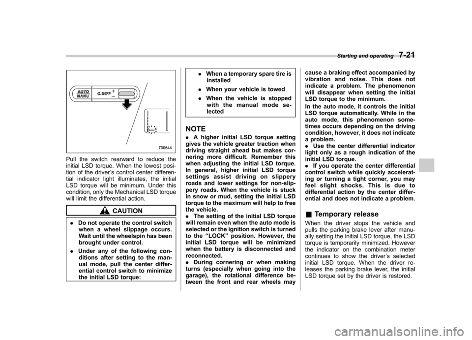
Pull the switch rearward to reduce the
initial LSD torque. When the lowest posi-
tion of the driver’s control center differen-
tial indicator light illuminates, the initial
LSD torque will be minimum. Under this
condition, only the Mechanical LSD torque
will limit the differential action.
CAUTION
. Do not operate the control switch
when a wheel slippage occurs.
Wait until the wheelspin has been
brought under control.
. Under any of the following con-
ditions after setting to the man-
ual mode, pull the center differ-
ential control switch to minimize
the initial LSD torque: .
When a temporary spare tire is
installed
. When your vehicle is towed
. When the vehicle is stopped
with the manual mode se-lected
NOTE . A higher initial LSD torque setting
gives the vehicle greater traction when
driving straight ahead but makes cor-
nering more difficult. Remember this
when adjusting the initial LSD torque.
In general, higher initial LSD torque
settings assist driving on slippery
roads and lower settings for non-slip-
pery roads. When the vehicle is stuck
in snow or mud, setting the initial LSD
torque to the maximum will help to free
the vehicle.. The setting of the initial LSD torque
will remain even when the auto mode is
selected or the ignition switch is turned
to the “LOCK ”position. However, the
initial LSD torque will be minimized
when the battery is disconnected andreconnected.. During cornering or when making
turns (especially when going into the
garage), the rotational difference be-
tween the front and rear wheels may cause a braking effect accompanied by
vibration and noise. This does not
indicate a problem. The phenomenon
will disappear when setting the initial
LSD torque to the minimum.
In the auto mode, it controls the initial
LSD torque automatically. While in the
auto mode, this phenomenon some-
times occurs depending on the driving
condition, however, it does not indicate
a problem..
Use the center differential indicator
light only as a rough indication of the
initial LSD torque.. If you operate the center differential
control switch while quickly accelerat-
ing or turning a tight corner, you may
feel slight shocks. This is due to
differential action by the center differ-
ential and does not indicate a problem. & Temporary release
When the driver stops the vehicle and
pulls the parking brake lever after manu-
ally setting the initial LSD torque, the LSD
torque is temporarily minimized. However
the indicator on the combination meter
continues to show the driver ’s selected
initial LSD torque. When the driver re-
leases the parking brake lever, the initial
LSD torque set by the driver is restored. Starting and operating
7-21
Page 278 of 416
Hill start assist system
CAUTION
The Hill start assist system is a
device only for helping the driver
to START the vehicle on an uphill
grade. To prevent accidents when
the vehicle is parked on a slope, be
sure to firmly set the parking brake.
When setting the parking brake,
make sure that the vehicle remains
stationary when the clutch pedal isreleased.
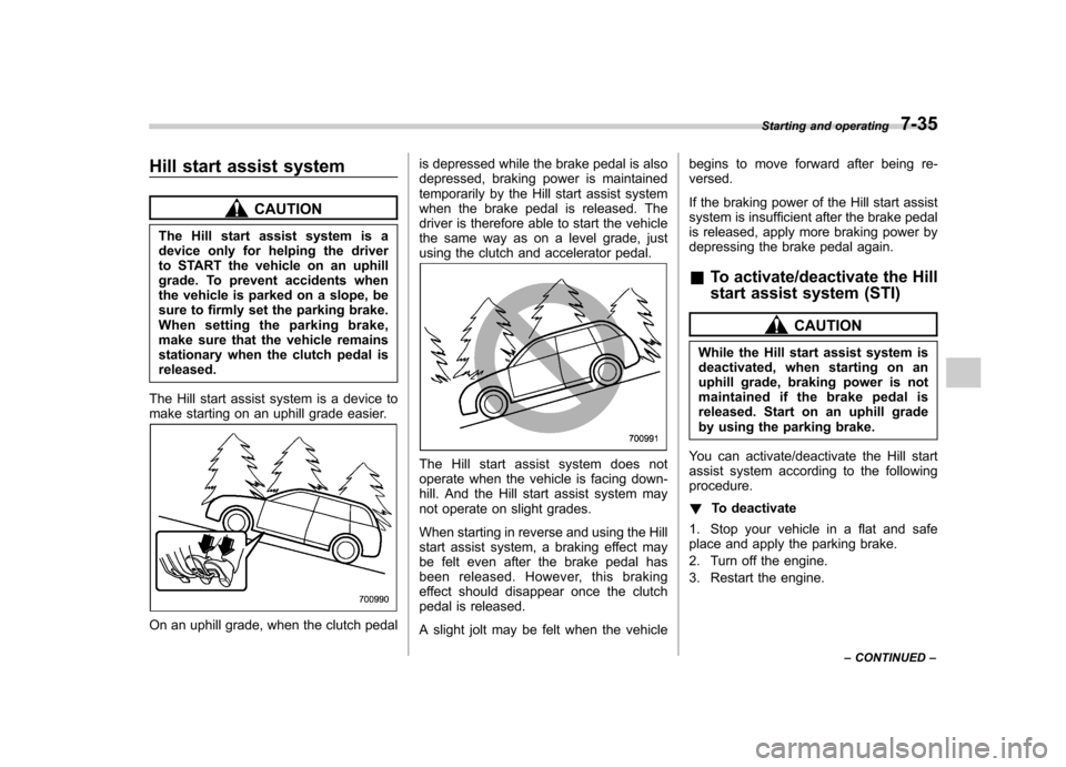
The Hill start assist system is a device to
make starting on an uphill grade easier.
On an uphill grade, when the clutch pedal is depressed while the brake pedal is also
depressed, braking power is maintained
temporarily by the Hill start assist system
when the brake pedal is released. The
driver is therefore able to start the vehicle
the same way as on a level grade, just
using the clutch and accelerator pedal.
The Hill start assist system does not
operate when the vehicle is facing down-
hill. And the Hill start assist system may
not operate on slight grades.
When starting in reverse and using the Hill
start assist system, a braking effect may
be felt even after the brake pedal has
been released. However, this braking
effect should disappear once the clutch
pedal is released.
A slight jolt may be felt when the vehiclebegins to move forward after being re- versed.
If the braking power of the Hill start assist
system is insufficient after the brake pedal
is released, apply more braking power by
depressing the brake pedal again. &
To activate/deactivate the Hill
start assist system (STI)
CAUTION
While the Hill start assist system is
deactivated, when starting on an
uphill grade, braking power is not
maintained if the brake pedal is
released. Start on an uphill grade
by using the parking brake.
You can activate/deactivate the Hill start
assist system according to the followingprocedure. ! To deactivate
1. Stop your vehicle in a flat and safe
place and apply the parking brake.
2. Turn off the engine.
3. Restart the engine. Starting and operating
7-35
– CONTINUED –
Page 319 of 416
10-4Appearance care
Corrosion protection
Your SUBARU has been designed and
built to resist corrosion. Special materials
and protective finishes have been used on
most parts of the vehicle to help maintain
fine appearance, strength, and reliableoperation. &Most common causes of corrosion
The most common causes of corrosion are:
1. The accumulation of moisture retain-
ing dirt and debris in body panel sections,
cavities, and other areas.
2. Damage to paint and other protective
coatings caused by gravel and stone
chips or minor accidents.
Corrosion is accelerated on the vehicle when:
1. It is exposed to road salt or dust
control chemicals, or used in coastal
areas where there is more salt in the air,
or in areas where there is considerable
industrial pollution.
2. It is driven in areas of high humidity,
especially when temperatures range just
above freezing.
3. Dampness in certain parts of the
vehicle remains for a long time, even though other parts of the vehicle may be
dry.
4. High temperatures will cause corro-
sion to parts of the vehicle which cannot
dry quickly due to lack of proper ventila-tion.
& To help prevent corrosion
Wash the vehicle regularly to prevent
corrosion of the body and suspension
components. Also, wash the vehicle
promptly after driving on any of the
following surfaces. . roads that have been salted to prevent
them from freezing in winter. mud, sand, or gravel
. coastal roads
After the winter has ended, it is recom-
mended that the underbody be given a
very thorough washing.
Before the beginning of winter, check the
condition of underbody components, such
as the exhaust system, fuel and brake
lines, brake cables, suspension, steering
system, floor pan, and fenders. If any of
them are found to be rusted, they should
be given an appropriate rust prevention
treatment or should be replaced. Contact
your SUBARU dealer to perform this kind
of maintenance and treatment if you need assistance.
Repair chips and scratches in the paint as
soon as you find them.
Check the interior of the vehicle for water
and dirt accumulation under the floor mats
because that could cause corrosion.
Occasionally check under the mats to
make sure the area is dry.
Keep your garage dry. Do not park your
vehicle in a damp, poorly ventilated
garage. In such a garage, corrosion can
be caused by dampness. If you wash the
vehicle in the garage or put the vehicle
into the garage when wet or covered with
snow, that can cause dampness.
If your vehicle is operated in cold weather
and/or in areas where road salts and other
corrosive materials are used, the door
hinges and locks, trunk lid lock, and hood
latch should be inspected and lubricated
periodically.
Page 322 of 416
Maintenance schedule....................................... 11-3
Maintenance precautions ................................... 11-3
Before checking or servicing in the engine compartment .................................................... 11-4
When checking or servicing in the engine compartment .................................................... 11-4
When checking or servicing in the engine compartment while the engine is running .......... 11-5
Engine hood ....................................................... 11-5
Engine compartment overview .......................... 11-6
Turbo models except STI .................................... 11-6
STI..................................................................... 11-7
Engine oil ............................................................ 11-8
Checking the oil level ......................................... 11-8
Changing the oil and oil filter .............................. 11-9
Recommended grade and viscosity .................. 11-10
Synthetic oil ..................................................... 11-10
Cooling system ................................................ 11-11
Cooling fan, hose and connections ................... 11-11
Engine coolant ................................................. 11-12
Air cleaner element .......................................... 11-13
Replacing the air cleaner element ..................... 11-13
Spark plugs ...................................................... 11-14
Recommended spark plugs .............................. 11-14
Drive belts ........................................................ 11-15
Manual transmission oil .................................. 11-15
Checking the oil level ....................................... 11-15
Recommended grade and viscosity .................. 11-16
Rear differential gear oil .................................. 11-16
Recommended grade and viscosity .................. 11-16Power steering fluid
........................................ 11-17
Checking the fluid level .................................... 11-17
Recommended fluid ......................................... 11-17
Brake fluid ........................................................ 11-18
Checking the fluid level .................................... 11-18
Recommended brake fluid ............................... 11-18
Clutch fluid ....................................................... 11-19
Checking the fluid level .................................... 11-19
Recommended clutch fluid ............................... 11-19
Brake booster .................................................. 11-20
Brake pedal ...................................................... 11-20
Checking the brake pedal free play .................. 11-20
Checking the brake pedal reserve distance....... 11-21
Clutch pedal ..................................................... 11-21
Checking the clutch function ............................ 11-21
Checking the clutch pedal free play .................. 11-21
Hill start assist system .................................... 11-22
Replacement of brake pad and lining ............ 11-22
Breaking-in of new brake pads and linings ....... 11-22
Parking brake stroke ....................................... 11-23
Tires and wheels .............................................. 11-23
Types of tires ................................................... 11-23
Tire pressure monitoring system (TPMS) (if equipped) ...................................................... 11-24
Tire inspection ................................................. 11-25
Tire pressures and wear .................................. 11-25
Wheel balance ................................................. 11-27
Wear indicators ............................................... 11-28
Tire rotation direction mark .............................. 11-28
Tire rotation ..................................................... 11-29
Maintenance and service
11
Page 343 of 416
11-22Maintenance and service
Hill start assist system
Ensure that the Hill start assist system
operates properly under the followingcircumstances:
1. Stop the vehicle on an uphill grade by
depressing the brake pedal and clutch
pedal, with the engine running.
2. Make sure that the vehicle does not
move backward even after the brake
pedal is released.
3. Then make sure the vehicle starts
climbing the grade by following the normal
starting procedures.
If the Hill start assist system does not
operate as described above, contact with
your SUBARU dealer. Replacement of brake pad
and lining
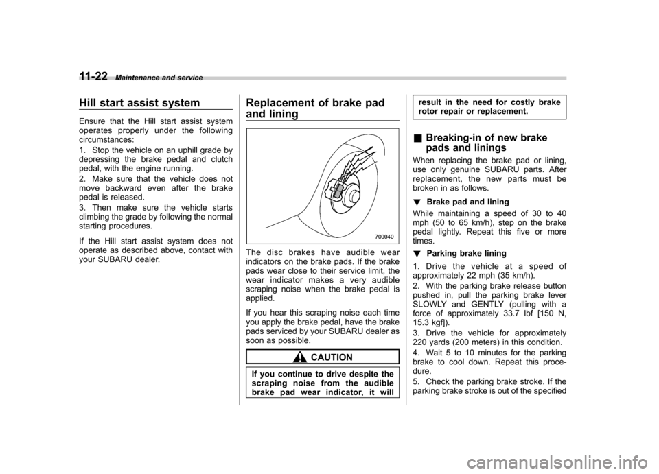
The disc brakes have audible wear
indicators on the brake pads. If the brake
pads wear close to their service limit, the
wear indicator makes a very audible
scraping noise when the brake pedal isapplied.
If you hear this scraping noise each time
you apply the brake pedal, have the brake
pads serviced by your SUBARU dealer as
soon as possible.
CAUTION
If you continue to drive despite the
scraping noise from the audible
brake pad wear indicator, it will result in the need for costly brake
rotor repair or replacement.
& Breaking-in of new brake
pads and linings
When replacing the brake pad or lining,
use only genuine SUBARU parts. After
replacement, the new parts must be
broken in as follows. ! Brake pad and lining
While maintaining a speed of 30 to 40
mph (50 to 65 km/h), step on the brake
pedal lightly. Repeat this five or moretimes. ! Parking brake lining
1. Drive the vehicle at a speed of
approximately 22 mph (35 km/h).
2. With the parking brake release button
pushed in, pull the parking brake lever
SLOWLY and GENTLY (pulling with a
force of approximately 33.7 lbf [150 N,
15.3 kgf]).
3. Drive the vehicle for approximately
220 yards (200 meters) in this condition.
4. Wait 5 to 10 minutes for the parking
brake to cool down. Repeat this proce-dure.
5. Check the parking brake stroke. If the
parking brake stroke is out of the specified
Page 405 of 416

14-2Index
A
ABS (Anti-lock Brake System) ..................................... 7-26
Warning light ......................................................... 3-18
Accessories ....................................................... 5-4, 11-39
Accessory power outlet ................................................. 6-8
Active head restraint ..................................................... 1-5
Air cleaner element ................................................... 11-13
Air conditioner Automatic climate control system ............................... 4-8
Manual climate control system ................................... 4-3
Air filtration system ..................................................... 4-13
Airflow selection Automatic climate control system ............................... 4-8
Manual climate control system ................................... 4-3
Alarm system ............................................................ 2-15
Aluminum wheel ....................................................... 11-30
Cleaning ............................................................... 10-3
Antenna system ........................................................... 5-3
Anti-lock Brake System (ABS) ..................................... 7-26
Arming the system ..................................................... 2-16
Armrest ....................................................................... 1-8
Ashtray ..................................................................... 6-10
Audio Antenna system ....................................................... 5-3
Auxiliary input jack ................................................. 5-23
Bluetooth
®audio .................................................... 5-33
CD player operation ............................................... 5-16
Control button ........................................................ 5-31
FM/AM radio operation ........................................... 5-10
iPod
®operations .................................................... 5-26
Power and sound controls ......................................... 5-7 Satellite radio operations
......................................... 5-13
Set ........................................................................ 5-4
USB storage device operations ................................ 5-26
Auto-dimming mirror/compass .............................. 3-37, 3-38
Automatic climate control system ................................... 4-8
Automatic transmission Fluid ..................................................................... 12-7
Automatic/Emergency Locking Retractor (A/ELR) ........... 1-12
Auxiliary input jack ...................................................... 5-23
B Battery .................................................................... 11-36
Drainage prevention function ..................................... 2-5
Jump starting .......................................................... 9-9
Replacement (remote engine start transmitter) ........... 7-12
Replacement (remote keyless entry system) .............. 2-11
Bluetooth
®audio ........................................................ 5-33
Booster seat .............................................................. 1-27
Bottle holder ............................................................... 6-7
Brake Assist .................................................................... 7-25
Booster ....................................................... 7-25, 11-20
Fluid ........................................................... 11-18, 12-7
Pad and lining ...................................................... 11-22
Parking ....................................................... 7-33, 11-23
Pedal .................................................................. 11-20
System .................................................................. 7-25
Brake pedal Free play ............................................................. 11-20
Reserve distance .................................................. 11-21
Brake system ............................................................. 7-25