tow SUBARU IMPREZA WRX 2012 4.G Owners Manual
[x] Cancel search | Manufacturer: SUBARU, Model Year: 2012, Model line: IMPREZA WRX, Model: SUBARU IMPREZA WRX 2012 4.GPages: 416, PDF Size: 14.37 MB
Page 15 of 416

12
Illustrated index &Exterior1) Engine hood (page 11-5)
2) Headlight switch (page 3-29)
3) Replacing bulbs (page 11-39)
4) Wiper switch (page 3-35)
5) Moonroof (page 2-27)
6) Door locks (page 2-4)
7) Tire pressure (page 11-25)
8) Flat tires (page 9-5)
9) Snow tires (page 8-8)
10) Front fog light switch (page 3-33)
11) Tie-down hooks (page 9-13)
12) Towing hook (page 9-13)
Page 16 of 416

1) Rear window defogger (page 3-45)
2) Fuel filler lid and cap (page 7-4)
3) Child safety locks (page 2-20)
4) Tie-down hook (page 9-13)
5) Trunk lid (page 2-23)
6) Rear gate (page 2-26)
7) Towing hook (page 9-13)13
– CONTINUED –
Page 45 of 416
1-16Seat, seatbelt and SRS airbags
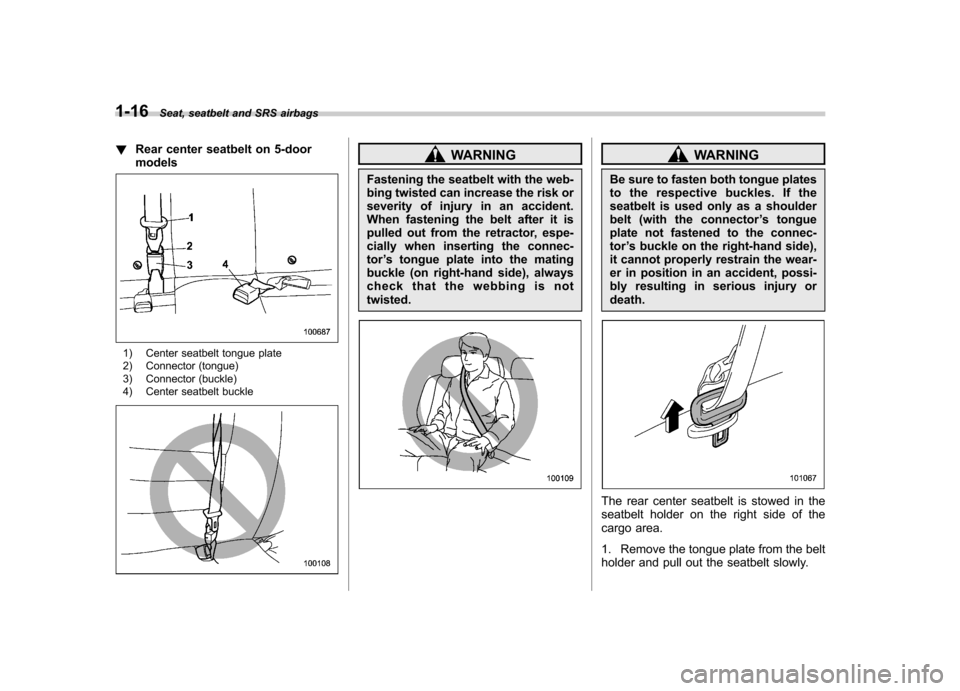
!Rear center seatbelt on 5-door models
1) Center seatbelt tongue plate
2) Connector (tongue)
3) Connector (buckle)
4) Center seatbelt buckle
WARNING
Fastening the seatbelt with the web-
bing twisted can increase the risk or
severity of injury in an accident.
When fastening the belt after it is
pulled out from the retractor, espe-
cially when inserting the connec-tor ’s tongue plate into the mating
buckle (on right-hand side), always
check that the webbing is nottwisted.WARNING
Be sure to fasten both tongue plates
to the respective buckles. If the
seatbelt is used only as a shoulder
belt (with the connector ’s tongue
plate not fastened to the connec-tor ’s buckle on the right-hand side),
it cannot properly restrain the wear-
er in position in an accident, possi-
bly resulting in serious injury ordeath.
The rear center seatbelt is stowed in the
seatbelt holder on the right side of the
cargo area.
1. Remove the tongue plate from the belt
holder and pull out the seatbelt slowly.
Page 66 of 416

WARNING
. Do not attach accessories to the
door trim or near either SRS side
airbags and do not place objects
near the SRS side airbags. In the
event of SRS side airbag deploy-
ment, they could be propelled
dangerously toward the vehicle ’s
occupants and cause injuries.
. Do not attach a hands-free micro-
phone or any other accessory to
a front pillar, a center pillar, a rear
pillar, the windshield, a side win-
dow, an assist grip, or any other
cabin surface that would be near
a deploying SRS curtain airbag.
A hands-free microphone or other accessory in such a loca-
tion could be propelled through
the cabin with great force by the
curtain airbag, or it could prevent
correct deployment of the curtain
airbag. In either case, the result
could be serious injuries.
. Never hang or place coat hangers
or other hard or pointed objects
near the side windows. If such
items are present when the SRS
curtain airbags deploy, they
could be thrown through the
passenger compartment and
cause serious injuries. They
could also prevent proper opera-
tion of the SRS curtain airbags.
Before hanging clothing on the
coat hooks, make sure there are
no sharp objects in the pockets.
Hang clothing directly on the
coat hooks without using hang-ers.WARNING
Do not put any kind of cover or
clothes or other objects over either
front seatback and do not attach
labels or stickers to the front seat
surface on or near the SRS side
airbag. They could prevent proper
deployment of the SRS side airbag,
reducing protection available to the
front seat ’s occupant.
Seat, seatbelt and SRS airbags
1-37
– CONTINUED –
Page 70 of 416
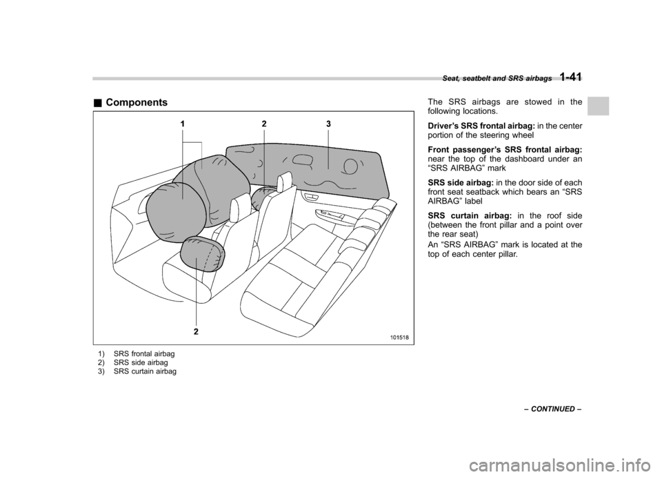
&Components
1) SRS frontal airbag
2) SRS side airbag
3) SRS curtain airbag The SRS airbags are stowed in the
following locations. Driver
’s SRS frontal airbag: in the center
portion of the steering wheel
Front passenger ’s SRS frontal airbag:
near the top of the dashboard under an “ SRS AIRBAG ”mark
SRS side airbag: in the door side of each
front seat seatback which bears an “SRS
AIRBAG ”label
SRS curtain airbag: in the roof side
(between the front pillar and a point over
the rear seat) An “SRS AIRBAG ”mark is located at the
top of each center pillar. Seat, seatbelt and SRS airbags
1-41
– CONTINUED –
Page 91 of 416
2-4Keys and doors
use with one vehicle.
Door locks &Locking and unlocking from
the outside
NOTE
If you unlock the driver ’s door with a
key and open the door while the alarm
system is armed, the alarm system is
triggered and the vehicle ’shorn
sounds. In this case, perform any of
the following operations: . Press any button on the remote
transmitter. . Insert the key into the ignition
switch and turn the ignition switch tothe “ON ”position.
For details about the alarm system,
refer to “Alarm system ”F 2-15.
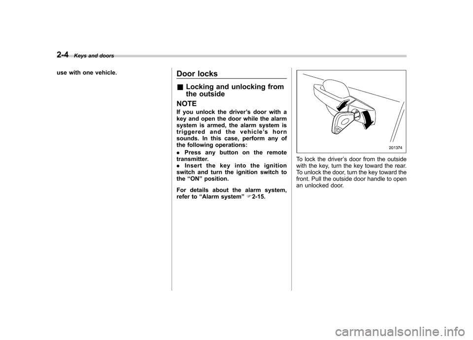
To lock the driver ’s door from the outside
with the key, turn the key toward the rear.
To unlock the door, turn the key toward the
front. Pull the outside door handle to open
an unlocked door.
Page 95 of 416
2-8Keys and doors
responsible for compliance
could void the user ’s authority
to operate the equipment.
This device complies with Part 15 of
the FCC Rules and RSS-Gen of IC
Rules. Operation is subject to the
following two conditions: (1) this de-
vice may not cause harmful interfer-
ence, and (2) this device must accept
any interference received, including
interference that may cause undesiredoperation.
Two transmitters are provided for your vehicle.
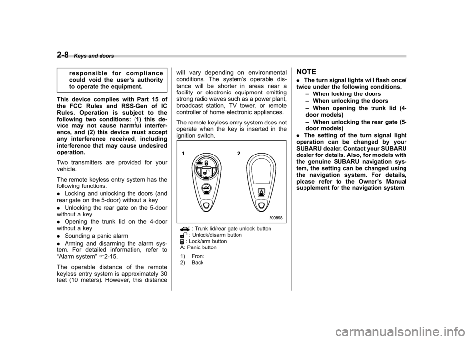
The remote keyless entry system has the
following functions. . Locking and unlocking the doors (and
rear gate on the 5-door) without a key. Unlocking the rear gate on the 5-door
without a key. Opening the trunk lid on the 4-door
without a key. Sounding a panic alarm
. Arming and disarming the alarm sys-
tem. For detailed information, refer to “ Alarm system ”F 2-15.
The operable distance of the remote
keyless entry system is approximately 30
feet (10 meters). However, this distance will vary depending on environmental
conditions. The system
’s operable dis-
tance will be shorter in areas near a
facility or electronic equipment emitting
strong radio waves such as a power plant,
broadcast station, TV tower, or remote
controller of home electronic appliances.
The remote keyless entry system does not
operate when the key is inserted in the
ignition switch.
: Trunk lid/rear gate unlock button: Unlock/disarm button: Lock/arm button
A: Panic button
1) Front
2) Back NOTE .
The turn signal lights will flash once/
twice under the following conditions.
–When locking the doors
– When unlocking the doors
– When opening the trunk lid (4-
door models) – When unlocking the rear gate (5-
door models)
. The setting of the turn signal light
operation can be changed by your
SUBARU dealer. Contact your SUBARU
dealer for details. Also, for models with
the genuine SUBARU navigation sys-
tem, the setting can be changed using
the navigation system. For details,
please refer to the Owner ’s Manual
supplement for the navigation system.
Page 120 of 416
Ignition switch
WARNING
. Never turn the ignition switch to
“ LOCK ”while the vehicle is
being driven or towed because
that will lock the steering wheel,
preventing steering control. And
when the engine is turned off, it
takes a much greater effort than
usual to steer.
. Before leaving the vehicle, al-
ways remove the key from the
ignition switch for safety and
never allow an unattended child
to remain in the vehicle. Failure
to follow this procedure could
result in injury to a child or
others. Children could operate
the power windows, the moon-
roof or other controls or even
make the vehicle move.
CAUTION
Do not attach a large key holder or
key case to either key. If it banged
against your knees or hands while
you are driving, it could turn the
ignition switch from the “ON ”posi- tion to the
“Acc ”or “LOCK ”posi-
tion, thereby stopping the engine.
Also, if the key is attached to a
keyholder or to a large bunch of
other keys, centrifugal force may act
on it as the vehicle moves, resulting
in unwanted turning of the ignitionswitch.
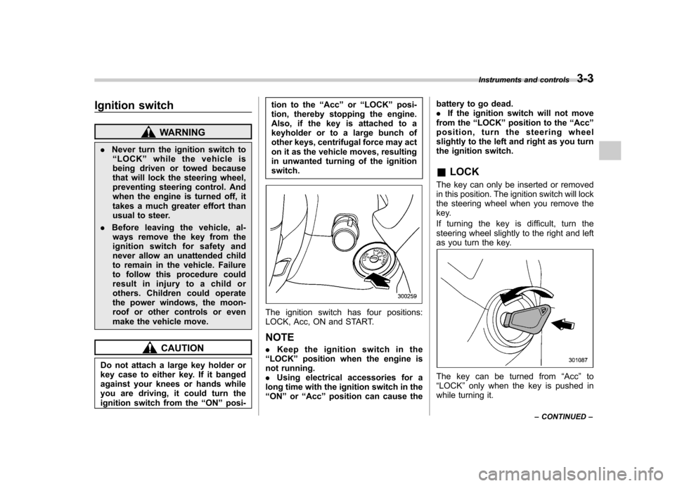
The ignition switch has four positions:
LOCK, Acc, ON and START. NOTE . Keep the ignition switch in the
“ LOCK ”position when the engine is
not running. . Using electrical accessories for a
long time with the ignition switch in the“ ON ”or “Acc ”position can cause the battery to go dead..
If the ignition switch will not move
from the “LOCK ”position to the “Acc ”
position, turn the steering wheel
slightly to the left and right as you turn
the ignition switch. & LOCK
The key can only be inserted or removed
in this position. The ignition switch will lock
the steering wheel when you remove the
key.
If turning the key is difficult, turn the
steering wheel slightly to the right and left
as you turn the key.
The key can be turned from “Acc ”to
“ LOCK ”only when the key is pushed in
while turning it. Instruments and controls
3-3
– CONTINUED –
Page 136 of 416
When the battery becomes fully charged,
the light will turn off. &Brake system
warning light
WARNING
. Driving with the brake system
warning light on is dangerous.
This indicates your brake system
may not be working properly. If
the light remains illuminated,
have the brakes inspected by a
SUBARU dealer immediately.
. If at all in doubt about whether
the brakes are operating prop-
erly, do not drive the vehicle.
Have your vehicle towed to the
nearest SUBARU dealer for re-
pair.
This light has the following functions. ! Parking brake warning
The light illuminates with the parking
brake applied while the ignition switch is
in the “ON ”position. It turns off when the
parking brake is fully released. ! Brake fluid level warning
This light illuminates when the brake fluid
level has dropped to near the “MIN ”level of the brake fluid reservoir with the ignition
switch in the
“ON ”position and with the
parking brake fully released.
If the brake system warning light should
illuminate while driving (with the parking
brake fully released and with the ignition
switch positioned in “ON ”), it could be an
indication of leaking of brake fluid or worn
brake pads. If this occurs, immediately
stop the vehicle at the nearest safe place
and check the brake fluid level. If the fluid
level is below the “MIN ”mark in the
reservoir, do not drive the vehicle. Have
the vehicle towed to the nearest SUBARU
dealer for repair. ! Electronic Brake Force Distribution
(EBD) system warning
The brake system warning light also
illuminates if a malfunction occurs in the
EBD system. In that event, it illuminates
together with the ABS warning light.
The EBD system may be malfunctioning if
the brake system warning light and ABS
warning light illuminate simultaneously
during driving.
Even if the EBD system fails, the conven-
tional braking system will still function.
However, the rear wheels will be more
prone to locking when the brakes are
applied harder than usual and the vehi-cle ’s motion may therefore become some- what harder to control.
If the brake system warning light and ABS
warning light illuminate simultaneously,
take the following steps.
1. Stop the vehicle in the nearest safe,
flat place.
2. Shut down the engine, apply the
parking brake and then restart it.
3. Release the parking brake. If both
warning lights turn off, the EBD system
may be malfunctioning. Drive carefully to
the nearest SUBARU dealer and have the
system inspected.
4. If both warning lights illuminate again
and remain illuminated after the engine
has been restarted, shut down the engine
again, apply the parking brake, and check
the brake fluid level.
5. If the brake fluid level is not below the “
MIN ”mark, the EBD system may be
malfunctioning. Drive carefully to the
nearest SUBARU dealer and have the
system inspected.
6. If the brake fluid level is below the “ MIN ”mark, DO NOT drive the vehicle.
Instead, have the vehicle towed to the
nearest SUBARU dealer for repair. Instruments and controls
3-19
– CONTINUED –
Page 147 of 416
3-30Instruments and controls
&Headlight flasher
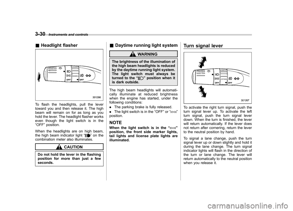
To flash the headlights, pull the lever
toward you and then release it. The high
beam will remain on for as long as you
hold the lever. The headlight flasher works
even though the light switch is in the“OFF ”position.
When the headlights are on high beam,
the high beam indicator light “
”on the
combination meter also illuminates.
CAUTION
Do not hold the lever in the flashing
position for more than just a fewseconds. &
Daytime running light system
WARNING
The brightness of the illumination of
the high beam headlights is reduced
by the daytime running light system.
The light switch must always be
turned to the “
”position when it
is dark outside.
The high beam headlights will automati-
cally illuminate at reduced brightness
when the engine has started, under the
following conditions: . The parking brake is fully released.
. The light switch is in the “OFF ”or “
”
position. NOTE
When the light switch is in the “
”
position, the front side marker lights,
tail lights and license plate lights areilluminated. Turn signal lever
To activate the right turn signal, push the
turn signal lever up. To activate the left
turn signal, push the turn signal lever
down. When the turn is finished, the lever
will return automatically. If the lever does
not return after cornering, return the lever
to the neutral position by hand.
To signal a lane change, push the turn
signal lever up or down slightly and hold it
during the lane change. The turn signal
indicator lights will flash in the direction of
the turn or lane change. The lever will
return automatically to the neutral position
when you release it.