maintenance SUBARU IMPREZA WRX 2013 4.G Owners Manual
[x] Cancel search | Manufacturer: SUBARU, Model Year: 2013, Model line: IMPREZA WRX, Model: SUBARU IMPREZA WRX 2013 4.GPages: 414, PDF Size: 14.23 MB
Page 4 of 414

Warranties &Warranties for U.S.A.
All SUBARU vehicles distributed by
Subaru of America, Inc. and sold at retail
by an authorized SUBARU dealer in the
United States come with the followingwarranties: . SUBARU Limited Warranty
. Emission Control Systems Warranty
. Emissions Performance Warranty
All warranty information, including details
of coverage and exclusions, is in the“ Warranty and Maintenance Booklet ”.
Please read these warranties carefully.
& Warranties for Canada
All SUBARU vehicles distributed by
Subaru Canada, Inc. and sold at retail by
an authorized SUBARU dealer in Canada
come with the following warranties: . SUBARU Limited Warranty
. Anti-Corrosion Warranty
. Emission Control Warranty
All warranty information, including details
of coverage and exclusions, is in the“ Warranty and Service Booklet ”. Please
read these warranties carefully. &
Models with HID headlights
CAUTION
High Intensity Discharge (HID) head-
lights contain mercury. For that
reason, it is necessary to remove
HID headlights before vehicle dis-
posal. Once removed, please reuse,
recycle or dispose of the HID head-
lights as hazardous waste.
& Models without HID head- lights
NOTE
This vehicle does not contain mercury
devices or parts. How to use this Owner
’s
Manual & Using your Owner ’s Manual
Before you operate your vehicle, carefully
read this manual. To protect yourself and
extend the service life of your vehicle,
follow the instructions in this manual.
Failure to observe these instructions may
result in serious injury and damage to yourvehicle.
This manual is composed of fourteen
chapters. Each chapter begins with a brief
table of contents, so you can usually tell at
a glance if that chapter contains the
information you want.
Chapter 1: Seat, seatbelt and SRS airbags
This chapter informs you how to use the
seat and seatbelt and contains precau-
tions for the SRS airbags.
Chapter 2: Keys and doors
This chapter informs you how to operate
the keys, locks and windows.
Chapter 3: Instruments and controls
This chapter informs you about the opera-
tion of instrument panel indicators and
how to use the instruments and otherswitches. 1
– CONTINUED –
Page 5 of 414
2
Chapter 4: Climate control
This chapter informs you how to operate
the climate control.
Chapter 5: Audio
This chapter informs you how to operate
your audio system.
Chapter 6: Interior equipment
This chapter informs you how to operate
interior equipment.
Chapter 7: Starting and operating
This chapter informs you how to start and
operate your SUBARU.
Chapter 8: Driving tips
This chapter informs you how to drive your
SUBARU in various conditions and ex-
plains some safety tips on driving.
Chapter 9: In case of emergency
This chapter informs you what to do if you
have a problem while driving, such as a
flat tire or engine overheating.
Chapter 10: Appearance care
This chapter informs you how to keep your
SUBARU looking good.
Chapter 11: Maintenance and service
This chapter informs you when you need
to take your SUBARU to the dealer for
scheduled maintenance and informs you
how to keep your SUBARU running
properly.Chapter 12: Specifications
This chapter informs you about dimen-
sions and capacities of your SUBARU.
Chapter 13: Consumer information and
Reporting safety defects
This chapter informs you about Uniform
tire quality grading standards and Report-
ing safety defects.
Chapter 14: Index
This is an alphabetical listing of all that
’sin
this manual. You can use it to quickly find
something you want to read.
& Safety warnings
You will find a number of WARNINGs,
CAUTIONs and NOTEs in this manual.
These safety warnings alert you to poten-
tial hazards that could result in injury to
you or others.
Please read these safety warnings as well
as all other portions of this manual care-
fully in order to gain a better understand-
ing of how to use your SUBARU vehicle
safely.
WARNING
A WARNING indicates a situation in
which serious injury or death could
result if the warning is ignored.
CAUTION
A CAUTION indicates a situation in
which injury or damage to your
vehicle, or both, could result if the
caution is ignored.
NOTE
A NOTE gives information or sugges-
tions how to make better use of yourvehicle. & Safety symbol
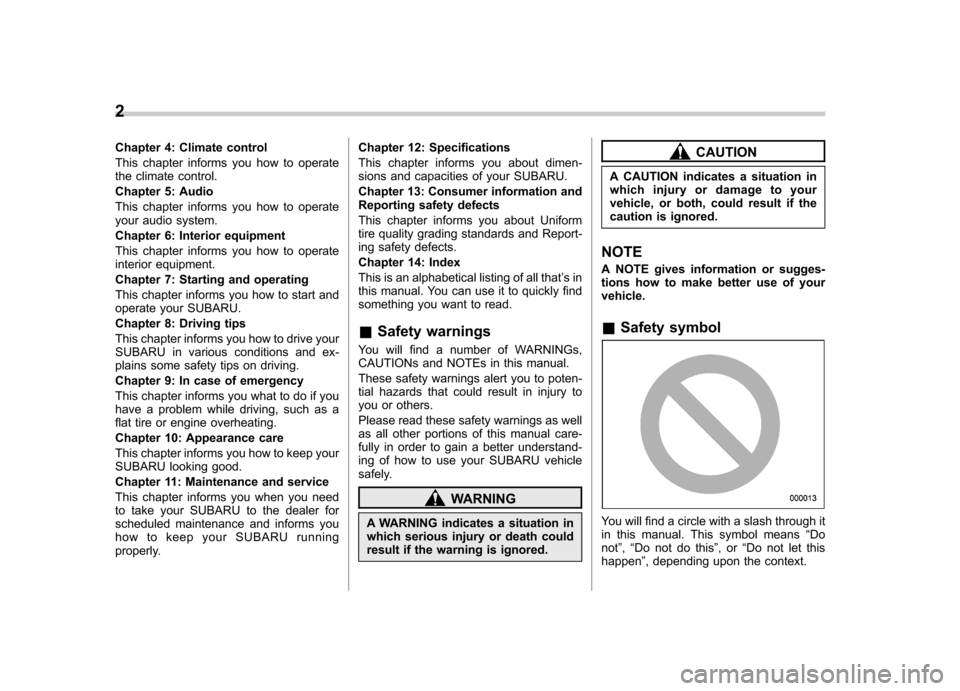
You will find a circle with a slash through it
in this manual. This symbol means “Do
not ”, “Do not do this ”,or “Do not let this
happen ”, depending upon the context.
Page 14 of 414

Table of contents
Seat, seatbelt and SRS airbags1
Keys and doors2
Instruments and controls
Climate control4
Audio5
Interior equipment6
Starting and operating7
Driving tips8
In case of emergency9
Appearance care10
Maintenance and service11
Specifications12
Consumer information and Reporting safety defects13
Index14
3
Page 28 of 414
Front seats........................................................... 1-2
Forward and backward adjustment ...................... 1-3
Reclining the seatback ........................................ 1-3
Seat cushion height adjustment (driver ’s seat) ..... 1-4
Head restraint adjustment (if equipped) ................ 1-4
Active head restraint (if equipped) ....................... 1-5
Seat heater (if equipped) .................................... 1-6
Type A seat heater .............................................. 1-6
Type B seat heater .............................................. 1-6
Rear seats ............................................................ 1-7
Armrest (if equipped) ........................................... 1-8
Head restraint adjustment .................................... 1-8
Folding down the rear seatback ........................... 1-9
Seatbelts ............................................................. 1-11
Seatbelt safety tips ............................................. 1-11
Emergency Locking Retractor (ELR) ................... 1-12
Automatic/Emergency Locking Retractor (A/ELR) ............................................................ 1-12
Seatbelt warning light and chime ........................ 1-12
Fastening the seatbelt ........................................ 1-12
Seatbelt maintenance ......................................... 1-19 Front seatbelt pretensioners
............................. 1-19
System monitors ............................................... 1-20
System servicing ............................................... 1-20
Precautions against vehicle modification ............ 1-21
Child restraint systems ..................................... 1-21
Where to place a child restraint system .............. 1-22
Choosing a child restraint system ...................... 1-24
Installing child restraint systems with A/ELR seatbelt ........................................................... 1-24
Installing a booster seat ..................................... 1-27
Installation of child restraint systems by use of lower and tether anchorages (LATCH) .............. 1-29
Top tether anchorages ....................................... 1-31
*SRS airbag (Supplemental Restraint System airbag) ................................................ 1-34
General precautions regarding SRS airbag system ............................................................ 1-34
Components ...................................................... 1-41
SUBARU advanced frontal airbag system, SRS side airbag and SRS curtain airbag .................. 1-43
System operation ............................................... 1-47
SRS airbag system monitors .............................. 1-55
SRS airbag system servicing ... .......................... 1-56
Precautions against vehicle modification ............ 1-57
Seat, seatbelt and SRS airbags1
Page 46 of 414
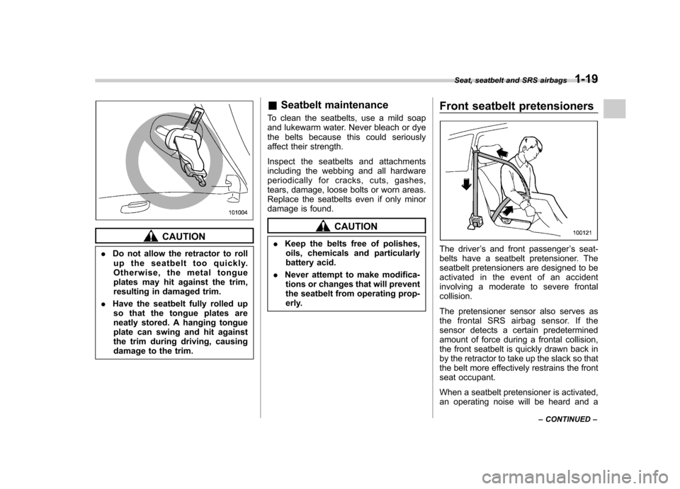
CAUTION
. Do not allow the retractor to roll
up the seatbelt too quickly.
Otherwise, the metal tongue
plates may hit against the trim,
resulting in damaged trim.
. Have the seatbelt fully rolled up
so that the tongue plates are
neatly stored. A hanging tongue
plate can swing and hit against
the trim during driving, causing
damage to the trim. &
Seatbelt maintenance
To clean the seatbelts, use a mild soap
and lukewarm water. Never bleach or dye
the belts because this could seriously
affect their strength.
Inspect the seatbelts and attachments
including the webbing and all hardware
periodically for cracks, cuts, gashes,
tears, damage, loose bolts or worn areas.
Replace the seatbelts even if only minor
damage is found.
CAUTION
. Keep the belts free of polishes,
oils, chemicals and particularly
battery acid.
. Never attempt to make modifica-
tions or changes that will prevent
the seatbelt from operating prop-
erly. Front seatbelt pretensioners
The driver
’s and front passenger ’s seat-
belts have a seatbelt pretensioner. The
seatbelt pretensioners are designed to be
activated in the event of an accident
involving a moderate to severe frontalcollision.
The pretensioner sensor also serves as
the frontal SRS airbag sensor. If the
sensor detects a certain predetermined
amount of force during a frontal collision,
the front seatbelt is quickly drawn back in
by the retractor to take up the slack so that
the belt more effectively restrains the front
seat occupant.
When a seatbelt pretensioner is activated,
an operating noise will be heard and a Seat, seatbelt and SRS airbags
1-19
– CONTINUED –
Page 124 of 414

NOTE
If the connection between the combina-
tion meter and battery is broken for any
reason such as vehicle maintenance or
fuse replacement, the data recorded on
the trip meter will be lost. &Tachometer
The tachometer shows the engine speed
in thousands of revolutions per minute.
CAUTION
Do not operate the engine with the
pointer of the tachometer in the red
zone. This may cause severe da-
mage to the engine. &
Fuel gauge
1) Low fuel warning light (Refer to “Low fuel
warning light ”F 3-20.)
The fuel gauge shows the approximate
amount of fuel remaining in the tank.
When the ignition switch is in the “LOCK ”
or “Acc ”position, the fuel gauge shows “E ”
even if the fuel tank contains fuel.
The gauge may move slightly during
braking, turning or acceleration due to fuel
level movement in the tank.
If you press the trip knob while the ignition
switch is in the “LOCK ”or “Acc ”position,
the fuel gauge will light up and indicate the
amount of fuel remaining in the tank.
If, while the fuel gauge is indicating the
amount of fuel remaining in the tank, you
(a) do not press the trip knob for 10 seconds or (b) open and close the driver
’s
door, the fuel gauge indication will turn off.
NOTE
You will see the “”sign in the fuel
gauge meter.
This indicates that the fuel filler door
(lid) is located on the right side of thevehicle. Instruments and controls
3-9
– CONTINUED –
Page 132 of 414
seconds to check that the tire pressure
monitoring system (TPMS) is functioning
properly. If there is no problem and all tires
are properly inflated, the light will turn off.
Each tire, including the spare (if provided),
should be checked monthly when cold
and inflated to the inflation pressure
recommended by the vehicle manufac-
turer on the vehicle placard or tire inflation
pressure label. (If your vehicle has tires of
a different size than the size indicated on
the vehicle placard or tire inflation pres-
sure label, you should determine the
proper tire inflation pressure for thosetires.)
As an added safety feature, your vehicle
has been equipped with a tire pressure
monitoring system (TPMS) that illuminates
a low tire pressure telltale when one or
more of your tires is significantly under-
inflated. Accordingly, when the low tire
pressure telltale illuminates, you should
stop and check your tires as soon as
possible, and inflate them to the proper
pressure. Driving on a significantly under-
inflated tire causes the tire to overheat and
can lead to tire failure. Under-inflation also
reduces fuel efficiency and tire tread life,
and may affect the vehicle’s handling and
stopping ability.
Please note that the TPMS is not a
substitute for proper tire maintenance, and it is the driver
’s responsibility to
maintain correct tire pressure, even if
under-inflation has not reached the level
to trigger illumination of the TPMS low tire
pressure telltale.
Your vehicle has also been equipped with
a TPMS malfunction indicator to indicate
when the system is not operating properly.
The TPMS malfunction indicator is com-
bined with the low tire pressure telltale.
When the system detects a malfunction,
the telltale will flash for approximately one
minute and then remain continuously
illuminated. This sequence will continue
upon subsequent vehicle start-ups as long
as the malfunction exists. When the
malfunction indicator is illuminated, the
system may not be able to detect or signal
low tire pressure as intended. TPMS
malfunctions may occur for a variety of
reasons, including the installation of re-
placement or alternate tires or wheels on
the vehicle that prevent the TPMS from
functioning properly. Always check the
TPMS malfunction telltale after replacing
one or more tires or wheels on your
vehicle to ensure that the replacement or
alternate tires and wheels allow the TPMS
to continue to function properly.
Should the warning light illuminate stea-
dily after blinking for approximately one
minute, have the system inspected by your nearest SUBARU dealer as soon aspossible.
WARNING
If this light does not illuminate
briefly after the ignition switch is
turned ON or the light illuminates
steadily after blinking for approxi-
mately one minute, you should have
your Tire Pressure Monitoring Sys-
tem checked at a SUBARU dealer as
soon as possible.
If this light illuminates while driving,
never brake suddenly and keep
driving straight ahead while gradu-
ally reducing speed. Then slowly
pull off the road to a safe place.
Otherwise an accident involving
serious vehicle damage and serious
personal injury could occur.
If this light still illuminates while
driving after adjusting the tire pres-
sure, a tire may have significant
damage and a fast leak that causes
the tire to lose air rapidly. If you have
a flat tire, replace it with a spare tire
as soon as possible.
When a spare tire is mounted or a
wheel rim is replaced without the
original pressure sensor/transmitter
being transferred, the Low tire pres- Instruments and controls
3-17
– CONTINUED –
Page 193 of 414

5-12Audio
seeks within that PTY group.
The control function returns to the normal
mode after approximately 10 seconds. &Displaying radio PS (Pro-
gram Service Name) and RT
(Radio Text)
Type A audio
Type B audio
If the PS (Program Service Name) and/or
RT (Radio Text) are available, pressingthe “TEXT ”button changes the display
among PS, RT and frequency. The initial
setting is “PS ”.
NOTE . The maximum number of characters
that can be displayed for PS is 8. . The maximum number of characters
that can be displayed for RT is 64. . If RT is 13 characters or longer,
press and hold the “TEXT ”button in
order to change the page. &
Station preset
! How to preset stations
1. Select the preferred reception mode.
2. Select the preferred station.
3. Press and hold one of the preset
buttons (from
to) to store the
frequency. If the button is pressed briefly,
the preceding selection will remain in the
memory.
NOTE . Up to six stations for each reception
mode may be preset. . If the connection between the radio
and battery is broken for any reason
such as vehicle maintenance or radio
removal, all stations stored in the
preset buttons are cleared. If this
occurs, it is necessary to reset the
preset buttons.. If a cell phone is placed near the
radio, it may cause the radio to emit
noise when a phone call is received.
This noise does not indicate a radiomalfunction. !
Selecting preset stations
1. Select the preferred reception mode.
2. Press the preferred preset button (from
to) briefly.
Page 197 of 414

5-16Audio
!Channel scan
Type A audio
Type B audio
Press the “SCAN ”button briefly to change
the radio to the SCAN mode. In this mode,
under the selected category, the radio
scans through the channel until a station
is found. The radio will stop at the station
for 5 seconds while displaying the channel
number, after which scanning will continue
until the entire channel has been scanned
from the low end to the high end.
Press the “SCAN ”button again to cancel
the SCAN mode and to stop on any
displayed channel.
& Channel preset
! How to preset channels
1. Press the “SAT ”button to select SAT1,
SAT2 and SAT3 reception.
2. Select the desired channel.
3. Press and hold one of the preset
buttons (from
to) to store the
channel. If the button is pressed briefly,
the preceding selection will remain in
memory. NOTE .
Up to six SAT1, SAT2 and SAT3
channels each may be preset. . If the connection between the radio
and battery is broken for any reason
such as vehicle maintenance or radio
removal, all channels stored in the
preset buttons are cleared. If this
occurs, it is necessary to reset the
preset buttons. ! Selecting preset channels
1. Press the “SAT ”button to select SAT1,
SAT2 or SAT3 reception.
2. Press the preferred preset button
briefly. & Display selection
Type A audio
Type B audio
Press the “TEXT ”button while receiving
the satellite radio to change the display as follows.
CD player operation NOTE . Make sure to always insert a disc
with the label side up. If a disc is
inserted with the label side down, the
player displays “CHECK DISC ”. Refer
to “When the following messages are
displayed ”F 5-22.
. If a disc is inserted during a radio
broadcast, the disc will interrupt thebroadcast.. After the last song finishes, the disc
will automatically return to track 1 (the
first track on the disc) and will auto-
matically play back. . The player is designed to be able to
play music CD-Rs and music CD-RWs,
but it may not be able to play certainones.. Mini CDs (i.e., 8 cm/3 inch CDs) are
not supported, and if inserted, they will
be immediately ejected.. CDs that can be played back are
accompanied by the following restric-tions.
–Maximum number of folders: 255
– Maximum number of files in a
folder: 255 – Maximum number of files on a
CD: 510
Page 244 of 414
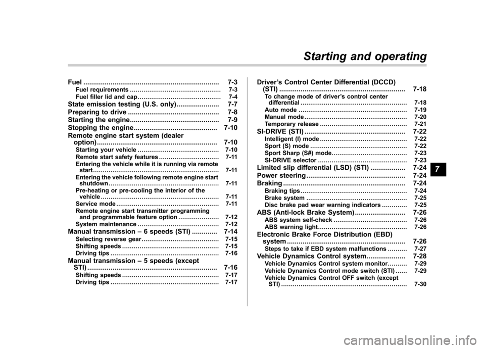
Fuel...................................................................... 7-3
Fuel requirements ............................................... 7-3
Fuel filler lid and cap ........................................... 7-4
State emission testing (U.S. only) ...................... 7-7
Preparing to drive ............................................... 7-8
Starting the engine .............................................. 7-9
Stopping the engine ........................................... 7-10
Remote engine start system (dealer option) .............................................................. 7-10
Starting your vehicle .......................................... 7-10
Remote start safety features ............................... 7-11
Entering the vehicle while it is running via remote start ................................................................. 7-11
Entering the vehicle following remote engine start shutdown ......................................................... 7-11
Pre-heating or pre-cooling the interior of the vehicle ............................................................. 7-11
Service mode ..................................................... 7-11
Remote engine start transmitter programming and programmable feature option ..................... 7-12
System maintenance .......................................... 7-12
Manual transmission –6 speeds (STI) ............. 7-14
Selecting reverse gear ........................................ 7-15
Shifting speeds .................................................. 7-15
Driving tips ........................................................ 7-16
Manual transmission –5 speeds (except
STI) ................................................................... 7-16
Shifting speeds .................................................. 7-17
Driving tips ........................................................ 7-17 Driver
’s Control Center Differential (DCCD)
(STI) ................................................................. 7-18
To change mode of driver ’s control center
differential ....................................................... 7-18
Auto mode ........................................................ 7-19
Manual mode ..................................................... 7-20
Temporary release ............................................. 7-21
SI-DRIVE (STI) .................................................... 7-22
Intelligent (I) mode ............................................. 7-22
Sport (S) mode .................................................. 7-22
Sport Sharp (S#) mode. ...................................... 7-23
SI-DRIVE selector .............................................. 7-23
Limited slip differential (LSD) (STI) .................. 7-24
Power steering ................................................... 7-24
Braking ............................................................... 7-24
Braking tips ....................................................... 7-24
Brake system .................................................... 7-25
Disc brake pad wear warning indicators ............. 7-25
ABS (Anti-lock Brake System) .......................... 7-26
ABS system self-check ...................................... 7-26
ABS warning light .............................................. 7-26
Electronic Brake Force Distribution (EBD) system ............................................................. 7-26
Steps to take if EBD system malfunctions ..... ..... 7-27
Vehicle Dynamics Control system .................... 7-28
Vehicle Dynamics Control system monitor..... ..... 7-29
Vehicle Dynamics Control mode switch (STI) . ..... 7-29
Vehicle Dynamics Control OFF switch (except STI) ................................................................. 7-30 Starting and operating
7