remote control SUBARU IMPREZA WRX 2013 4.G Owners Manual
[x] Cancel search | Manufacturer: SUBARU, Model Year: 2013, Model line: IMPREZA WRX, Model: SUBARU IMPREZA WRX 2013 4.GPages: 414, PDF Size: 14.23 MB
Page 27 of 414

24
Function settings
A SUBARU dealer can change the settings of the functions shown in the following table to meet your personal requirements. Contact
the nearest SUBARU dealer for details.Item Function Possible settings Default setting Page
Alarm system Alarm system Operation/Non-operation Operation 2-15
Monitoring start delay time (after
closure of doors)0 second/30 seconds 30 seconds 2-16
Impact sensor operation (only models
with shock sensors (dealer option)) Operation/Non-operation Non-operation 2-19
Passive arming Operation/Non-operation Non-operation 2-18
Dome light and map lights illumination
(models with moonroof) ON/OFF OFF 2-15
Dome light illumination
(models without moonroof)
Remote keyless entry system Hazard warning flasher Operation/Non-operation Operation 2-7 Audible signal Operation/Non-operation Operation 2-10
Key lock-in prevention Key lock-in prevention Operation/Non-operation Operation 2-7
Remote engine start system
(dealer option) Horn chirp confirmation ON/OFF ON 7-12
Defogger and deicer system for models
with the automatic climate control system Rear window defogger, outside mirror
defogger and windshield wiper deicerOperation for 15 minutes/
Continuous operationOperation for 15 minutes 3-46
Dome light Operation of dome light/map light OFF delay timerOFF/Short/Normal/Long Long 6-2, 6-3
Map light for models with a moonroof
Battery drainage prevention function Battery drainage prevention function Operation/Non-operation Operation 2-5
Seatbelt warning Sounds a chime while driving Operation/Non-operation Operation 3-13
Page 88 of 414
stantly, the immobilizer system does not
impede normal starting of the engine.
If the engine fails to start, pull out the key
once before trying again. Refer to“Ignition
switch ”F 3-3.
This device complies with Part 15 of
the FCC Rules and RSS-Gen of IC
Rules. Operation is subject to the
following two conditions: (1) this de-
vice may not cause harmful interfer-
ence, and (2) this device must accept
any interference received, including
interference that may cause undesiredoperation.
CAUTION
. Do not place the key under direct
sunlight or anywhere it may
become hot.
. Do not get the key wet. If the key
gets wet, wipe it dry with a cloth
immediately.
NOTE
To protect your vehicle from theft,
please pay close attention to the fol-
lowing security precautions: . Never leave your vehicle unattended
with its keys inside. . Before leaving your vehicle, close all windows and the moonroof, and lock
the doors and rear gate..
Do not leave spare keys or any
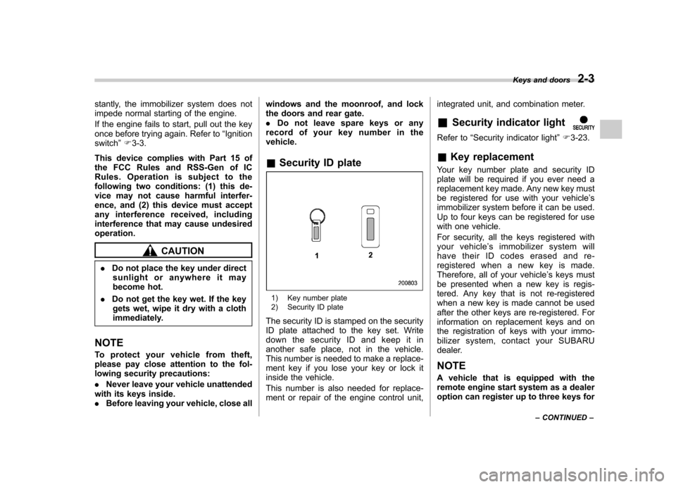
record of your key number in thevehicle. & Security ID plate
1) Key number plate
2) Security ID plate
The security ID is stamped on the security
ID plate attached to the key set. Write
down the security ID and keep it in
another safe place, not in the vehicle.
This number is needed to make a replace-
ment key if you lose your key or lock it
inside the vehicle.
This number is also needed for replace-
ment or repair of the engine control unit, integrated unit, and combination meter. &
Security indicator light
Refer to “Security indicator light ”F 3-23.
& Key replacement
Your key number plate and security ID
plate will be required if you ever need a
replacement key made. Any new key must
be registered for use with your vehicle ’s
immobilizer system before it can be used.
Up to four keys can be registered for use
with one vehicle.
For security, all the keys registered with
your vehicle ’s immobilizer system will
have their ID codes erased and re-
registered when a new key is made.
Therefore, all of your vehicle ’s keys must
be presented when a new key is regis-
tered. Any key that is not re-registered
when a new key is made cannot be used
after the other keys are re-registered. For
information on replacement keys and on
the registration of keys with your immo-
bilizer system, co ntact your SUBARU
dealer.
NOTE
A vehicle that is equipped with the
remote engine start system as a dealer
option can register up to three keys for Keys and doors
2-3
– CONTINUED –
Page 93 of 414

2-8Keys and doors
responsible for compliance
could void the user ’s authority
to operate the equipment.
This device complies with Part 15 of
the FCC Rules and RSS-Gen of IC
Rules. Operation is subject to the
following two conditions: (1) this de-
vice may not cause harmful interfer-
ence, and (2) this device must accept
any interference received, including
interference that may cause undesiredoperation.
Two transmitters are provided for your vehicle.
The remote keyless entry system has the
following functions. . Locking and unlocking the doors (and
rear gate on the 5-door) without a key. Unlocking the rear gate on the 5-door
without a key. Opening the trunk lid on the 4-door
without a key. Sounding a panic alarm
. Arming and disarming the alarm sys-
tem. For detailed information, refer to “ Alarm system ”F 2-15.
The operable distance of the remote
keyless entry system is approximately 30
feet (10 meters). However, this distance will vary depending on environmental
conditions. The system
’s operable dis-
tance will be shorter in areas near a
facility or electronic equipment emitting
strong radio waves such as a power plant,
broadcast station, TV tower, or remote
controller of home electronic appliances.
The remote keyless entry system does not
operate when the key is inserted in the
ignition switch.
: Trunk lid/rear gate unlock button: Unlock/disarm button: Lock/arm button
A: Panic button
1) Front
2) Back NOTE
The turn signal lights will flash once/
twice under the following conditions. .
When locking the doors
. When unlocking the doors
. When opening the trunk lid (4-door
models) . When unlocking the rear gate (5-
door models)
Operation of the turn signal light in the
above cases can be set to “On ”or
“ Off ”by a SUBARU dealer. Consult
your SUBARU dealer for details.
Page 96 of 414
&Replacing the battery
CAUTION
. Do not let dust, oil or water get on
or in the transmitter when repla-
cing the battery.
. Be careful not to damage the
printed circuit board in the trans-
mitter when replacing the battery.
. Be careful not to allow children to
touch the battery and any re-
moved parts; children could
swallow them.
. There is a danger of explosion if
an incorrect replacement battery
is used. Replace only with the
same or equivalent type of bat-
tery.
. Batteries should not be exposed
to excessive heat such as sun-
shine, fire or the like.
When the transmitter battery begins to get
weak, transmitter range will begin to
decrease. Replace the battery as soon
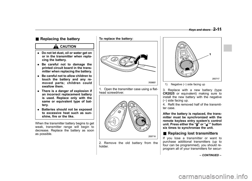
as possible. To replace the battery:
1. Open the transmitter case using a flat-
head screwdriver.
2. Remove the old battery from the
holder.
1) Negative (
�) side facing up
3. Replace with a new battery (type CR2025 or equivalent) making sure to
install the new battery with the negative( � ) side facing up.
4. Refit the removed half of the transmit-
ter case.
After the battery is replaced, the trans-
mitter must be synchronized with the
remote keyless entry system ’s control
unit. Press either the “
”or “”button
six times to synchronize the unit. & Replacing lost transmitters
If you lose a transmitter or want to
purchase additional transmitters (up to
four can be programmed), you should re-
program all of your transmitters for secur- Keys and doors
2-11
– CONTINUED –
Page 99 of 414

2-14Keys and doors
7. Perform parts 5 and 6 of the procedure
for each of the remaining digits of the
transmitter code beginning with the sec-
ond digit (counting from the left) and
finishing with the eighth digit. NOTE . When you finish entering the eighth
digit, an electronic tone will sound for
30 seconds.. If the interval between one push of
the switch and the next exceeds 5
seconds, an error will occur. In this
event, perform the procedure again
beginning with part 4. If an error occurs
six times, perform the procedure again
starting with part 3.
8. Before the electronic tone stops
sounding, use the power door lock switch
to reenter the transmitter code beginning
with the leftmost digit. NOTE
If you do not start entering the number
using the lock switch before the elec-
tronic tone stops sounding, an error
will occur. In this event, perform the
procedure again beginning with part 3.
9. When you have finished entering the
code a second time, an electronic tone will
sound for 1 second and automatic door
locking and unlocking operation will take place once to indicate completion of
registration, provided the code entered
the second time is identical to that entered
the first time.
NOTE
If the code entered the second time is
not identical to the code entered the
first time, an error will occur. In this
event, perform the procedure again
beginning with part 5. If an error occurs
five times, perform the procedure again
starting with part 3.
10. If you wish to program another trans-
mitter code into the system (up to four
transmitter codes can be programmed into
the system), perform the procedure begin-
ning with part 4. When you have finished
programming all of the necessary trans-
mitter codes into the system, remove the
key from the ignition switch.
11. Test every registered transmitter to
confirm correct operation. ! Deleting old transmitter codes
The control unit of the remote keyless
entry system has four memory locations to
store transmitter codes, giving it the ability
to operate with up to four transmitters.
When you lose a transmitter, the losttransmitter ’s code remains in the memory.
For security reasons, lost transmitter codes should be deleted from the mem-
ory.
To delete old transmitter codes, program
four transmitter codes into the system. If
you have only one current transmitter,
program it four times. If you have two
current transmitters, program each one
twice. If you have three current transmit-
ters, program two of them once and the
third one twice. This process will leave
only current transmitter codes in thesystem
’s memory.
NOTE
Make sure no one else is operating
their keyless entry system within range
of your vehicle when programming
transmitters. If someone else were to
operate their remote transmitter while
you are programming your transmit-
ters, it is possible that their transmitter
code will be programmed into your
system, allowing them unauthorized
access to your vehicle.
Page 119 of 414
3-4Instruments and controls
&Acc
In this position the electrical accessories
(audio, accessory power outlet, etc.) can
be used. & ON
This is the normal operating position after
the engine is started. & START
The engine is started in this position. The
starter cranks the engine to start it. When
the key is released (after the engine has
started), the key automatically returns tothe “ON ”position.
CAUTION
Do not turn the ignition switch to the “ START ”position while the engine
is running.
If your registered key fails to start the
engine, pull out the key once (the security
indicator light will blink), and then insert
the key in the ignition switch and turn it tothe “START ”position and again try to start
the engine. NOTE
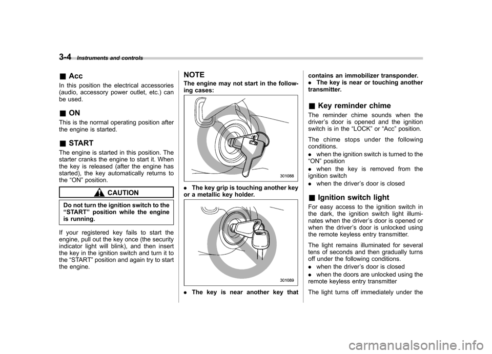
The engine may not start in the follow-
ing cases:.
The key grip is touching another key
or a metallic key holder.
. The key is near another key that contains an immobilizer transponder. .
The key is near or touching another
transmitter. & Key reminder chime
The reminder chime sounds when the driver ’s door is opened and the ignition
switch is in the “LOCK ”or “Acc ”position.
The chime stops under the followingconditions. . when the ignition switch is turned to the
“ ON ”position
. when the key is removed from the
ignition switch. when the driver ’s door is closed
& Ignition switch light
For easy access to the ignition switch in
the dark, the ignition switch light illumi-
nates when the driver ’s door is opened or
when the driver ’s door is unlocked using
the remote keyless entry transmitter.
The light remains illuminated for several
tens of seconds and then gradually turns
off under the following conditions. . when the driver ’s door is closed
. when the doors are unlocked using the
remote keyless entry transmitter
The light turns off immediately under the
Page 120 of 414
following conditions. .when the ignition switch is turned to the
“ ON ”position
. when all doors and the rear gate (5-
door) are locked using the remote keyless
entry transmitter Hazard warning flasher
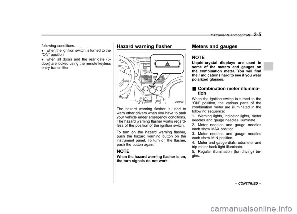
The hazard warning flasher is used to
warn other drivers when you have to park
your vehicle under emergency conditions.
The hazard warning flasher works regard-
less of the position of the ignition switch.
To turn on the hazard warning flasher,
push the hazard warning button on the
instrument panel. To turn off the flasher,
push the button again. NOTE
When the hazard warning flasher is on,
the turn signals do not work.Meters and gauges NOTE
Liquid-crystal displays are used in
some of the meters and gauges on
the combination meter. You will find
their indications hard to see if you wear
polarized glasses. &
Combination meter illumina- tion
When the ignition switch is turned to the “ ON ”position, the various parts of the
combination meter are illuminated in the
following sequence:
1. Warning lights, indicator lights, meter
needles and gauge needles illuminate.
2. Meter needles and gauge needles
each show MAX position.
3. Meter needles and gauge needles
each show MIN position.
4. Meter and gauge dials, odometer and
trip meter back light illuminate.
5. Regular illumination (for driving) be- gins. Instruments and controls
3-5
– CONTINUED –
Page 122 of 414
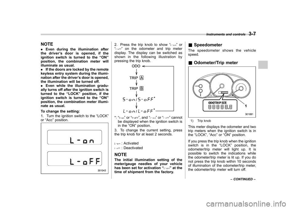
NOTE .Even during the illumination after
the driver ’s door is opened, if the
ignition switch is turned to the “ON ”
position, the combination meter will
illuminate as usual.. If the doors are locked by the remote
keyless entry system during the illumi-
nation after the driver ’s door is opened,
the illumination will be turned off.. Even while the illumination gradu-
ally turns off after the ignition switch is
turned to the “LOCK ”position, if the
ignition switch is turned to the “ON ”
position, the combination meter illumi-
nate as usual.
To change the setting:
1. Turn the ignition switch to the “LOCK ”
or “Acc ”position.2. Press the trip knob to show “”or
“” on the odometer and trip meter
display. The display can be switched as
shown in the following illustration by
pressing the trip knob.
*: “”or “”, and “”or “”cannot
be displayed when the ignition switch is
in the “ON ”position.
3. To change the current setting, press
the trip knob for at least 2 seconds.
: Activated
: Deactivated
NOTE
The initial illumination setting of the
meter/gauge needles of your vehicle
has been set for activation “
”at the
time of shipment from the factory. &
Speedometer
The speedometer shows the vehicle speed. & Odometer/Trip meter
1) Trip knob
This meter displays the odometer and two
trip meters when the ignition switch is inthe “LOCK ”, “Acc ”or “ON ”position.
If you press the trip knob when the ignition
switch is in the “LOCK ”position, the
odometer/trip meter will light up. It is
possible to switch the indications while
the odometer/trip meter is lit up. If you do
not press the trip knob within 10 seconds
of illumination of the odometer/trip meter,
the odometer/trip meter will turn off. Instruments and controls
3-7
– CONTINUED –
Page 156 of 414
!Compass calibration
1. If a “C ” is displayed in the compass
window, the compass needs to be cali- brated.
2. Drive the vehicle in a circle at 5 mph (8
km/h) or less until the display reads a direction.
3. You can also calibrate the compass by
driving your vehicle on your everyday
routine. The compass will be calibrated
once it has tracked a complete circle.
4. To recalibrate your compass, push and
hold the compass display button for 9
seconds until a “C ” appears in the
compass window.
5. Calibrate the compass according to
step 2 or step 3. ! HomeLink
®Wireless Control Sys-
tem
The HomeLink
®Wireless Control System
can be used to activate remote control
devices such as gate operators, garage
door openers, door locks, home lighting
and security systems.
There are three HomeLink
®buttons on the
mirror, each of which can be programmed
for operation of one desired device. For
details on the device types which can be
operated by this system, consult the HomeLink
®website at: www.homelink.com or call 1-800-355-3515.
Note the following information about this system.
Ifyourvehicleisequippedwiththe HomeLink
®Wireless Control System, it
complies with Part 15 of the Federal
Communications Commission Rules in
the U.S. and the RSS-210 of Industry
Canada in Canada. Its operation is subject
to the following two conditions:
(1) this device may not cause harmful
interference, and (2) this device must
accept any interference received, includ-
ing interference that may cause undesiredoperation.
Changes and modifications to this system
by anyone other than an authorized
service facility could void authorization to
use this equipment. HomeLink
®and the HomeLink®house are
registered trademarks of Johnson Con-
trols, Inc.
WARNING
. When programming the
HomeLink
®Wireless Control Sys-
tem, you may be operating a
garage door opener or other
device. Make sure that people and objects are out of the way of
the garage door or other device
to prevent potential harm ordamage.
. Do not use the HomeLink
®Wire-
less Control System with a gar-
age door opener that lacks the
safety stop and reverse feature
as required by applicable safety
standards. A garage door opener
which cannot detect an object,
signaling the door to stop and
reverse, does not meet these
safety standards. Using a garage
door opener without these fea-
tures increases risk of serious
injury or death. For more infor-
mation, consult the HomeLink
®website at www.homelink.com or
call 1-800-355-3515.
CAUTION
When programming the HomeLink
®Wireless Control System to operate
a garage door opener or an entrance
gate, unplug the device ’s motor
from the outlet during programming
to prevent motor burnout. Instruments and controls
3-41
– CONTINUED –
Page 159 of 414
3-44Instruments and controls
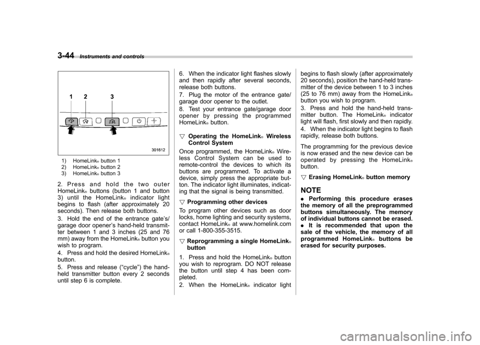
1) HomeLink®button 1
2) HomeLink®button 2
3) HomeLink®button 3
2. Press and hold the two outer HomeLink
®buttons (button 1 and button
3) until the HomeLink®indicator light
begins to flash (after approximately 20
seconds). Then release both buttons.
3. Hold the end of the entrance gate ’s/
garage door opener ’s hand-held transmit-
ter between 1 and 3 inches (25 and 76
mm) away from the HomeLink
®button you
wish to program.
4. Press and hold the desired HomeLink
®button.
5. Press and release ( “cycle ”) the hand-
held transmitter button every 2 seconds
until step 6 is complete. 6. When the indicator light flashes slowly
and then rapidly after several seconds,
release both buttons.
7. Plug the motor of the entrance gate/
garage door opener to the outlet.
8. Test your entrance gate/garage door
opener by pressing the programmedHomeLink
®button.
! Operating the HomeLink
®Wireless
Control System
Once programmed, the HomeLink
®Wire-
less Control System can be used to
remote-control the devices to which its
buttons are programmed. To activate a
device, simply press the appropriate but-
ton. The indicator light illuminates, indicat-
ing that the signal is being transmitted. ! Programming other devices
To program other devices such as door
locks, home lighting and security systems,
contact HomeLink
®at www.homelink.com
or call 1-800-355-3515. ! Reprogramming a single HomeLink
®button
1. Press and hold the HomeLink
®button
you wish to reprogram. DO NOT release
the button until step 4 has been com-pleted.
2. When the HomeLink
®indicator light begins to flash slowly (after approximately
20 seconds), position the hand-held trans-
mitter of the device between 1 to 3 inches
(25 to 76 mm) away from the HomeLink
®button you wish to program.
3. Press and hold the hand-held trans-
mitter button. The HomeLink
®indicator
light will flash, first slowly and then rapidly.
4. When the indicator light begins to flash
rapidly, release both buttons.
The programming for the previous device
is now erased and the new device can be
operated by pressing the HomeLink
®button. ! Erasing HomeLink
®button memory
NOTE . Performing this procedure erases
the memory of all the preprogrammed
buttons simultaneously. The memory
of individual buttons cannot be erased.. It is recommended that upon the
sale of the vehicle, the memory of all
programmed HomeLink
®buttons be
erased for security purposes.