air condition SUBARU IMPREZA WRX 2014 4.G Owner's Manual
[x] Cancel search | Manufacturer: SUBARU, Model Year: 2014, Model line: IMPREZA WRX, Model: SUBARU IMPREZA WRX 2014 4.GPages: 414, PDF Size: 14.22 MB
Page 175 of 414

4-10Climate control/Automatic climate control system
(Bi-level): Instrument panel outlets and
foot outlets
(Heat): Foot outlets, both side outlets of
the instrument panel and some through
windshield defroster outlets (A small
amount of air flows to the windshield and
both side windows to prevent fogging.)
(Heat-def): Windshield defroster out-
lets, foot outlets and both side outlets of
the instrument panel
: Windshield defroster outlets and both
side outlets of the instrument panel
For details, refer to “Airflow selection ”F 4-
2. NOTE
When the dial is placed in the “
”or
“” position, the air inlet selection is
automatically set to “outside air ”
mode. &
Air inlet selection button
ON position (recirculation): Interior air is
recirculated inside the vehicle. Press the
air inlet selection button to the ON position
for fast cooling with the air conditioner or
when driving on a dusty road. The
indicator light will illuminate.
OFF position (outside air): Outside air is
drawn into the passenger compartment.
Press the air inlet selection button to the
OFF position when the interior has cooled
to a comfortable temperature and the road
is no longer dusty. The indicator light will
turn off. AUTO: Turn the fan speed control dial and
airflow control dial to the AUTO position.
The air inlet control is then adjusted
automatically in accordance with the air
temperature inside and outside the pas- senger compartment, the intensity of sun-
light, and other factors. Pressing the air
inlet selection button cancels the
“AUTO ”
mode. To return to “AUTO ”mode, turn the
fan speed control dial or airflow control
dial to a position other than the AUTO
position. Then turn to “AUTO ”mode.
SUBARU recommends using the AUTOposition.
WARNING
Continued operation in the ON posi-
tion may fog up the windows. Switch
to the OFF position as soon as the
outside dusty condition clears.
NOTE
When the battery is disconnected or
when the battery voltage is low, the
indicator light will blink but this is not a
malfunction. However, an electrical
system malfunction may occur if the
indicator light is blinking when the
engine is started. Have your vehicle
inspected by a SUBARU dealer.
Page 176 of 414

&Air conditioner button
The button positions and their functions
are as follows. ON: The air conditioner operates while the
fan is running.
Press the button to select this position.
The indicator light will illuminate. OFF: The air conditioner does not oper-
ate.
Press the button again to select this
position. The indicator light will turn off. AUTO: Turn the fan speed control dial and
airflow control dial to the AUTO position.
The air conditioner compressor operation
is then adjusted automatically in accor-
dance with the air temperature inside and
outside the passenger compartment, the
intensity of sunlight, and other factors. Pressing the button cancels the
“AUTO ”
mode. To return to “AUTO ”mode, turn the
fan speed control dial or airflow control
dial to a position other than the AUTO
position. Then turn to “AUTO ”mode.
SUBARU recommends using the AUTOposition.
NOTE
For efficient defogging or dehumidify-
ing in cold weather, turn on the air
conditioner. However, if the ambient
temperature decreases to approxi-
mately 32 8F(0 8C), the air conditioner
and dehumidification system may not
work properly. &
Temperature sensors
1) Interior air temperature sensor
2) Solar sensor
The automatic climate control system
employs several sensors. These sensors
are delicate. If they are not treated
Climate control/Automatic climate control system4-11
– CONTINUED –
Page 177 of 414
4-12Climate control/Operating tips for heater and air conditioner
properly and become damaged, the sys-
tem may not be able to control the interior
temperature correctly. To avoid damaging
the sensors, observe the following pre-cautions. –Do not subject the sensors to impact.
– Keep water away from the sensors.
– Do not cover the sensors.
The sensors are located as follows.– Solar sensor: beside the windshield
defroster grille.– Interior air temperature sensor: near
the ignition switch.– Outside temperature sensor: behind
the front grille. Operating tips for heater and
air conditioner &
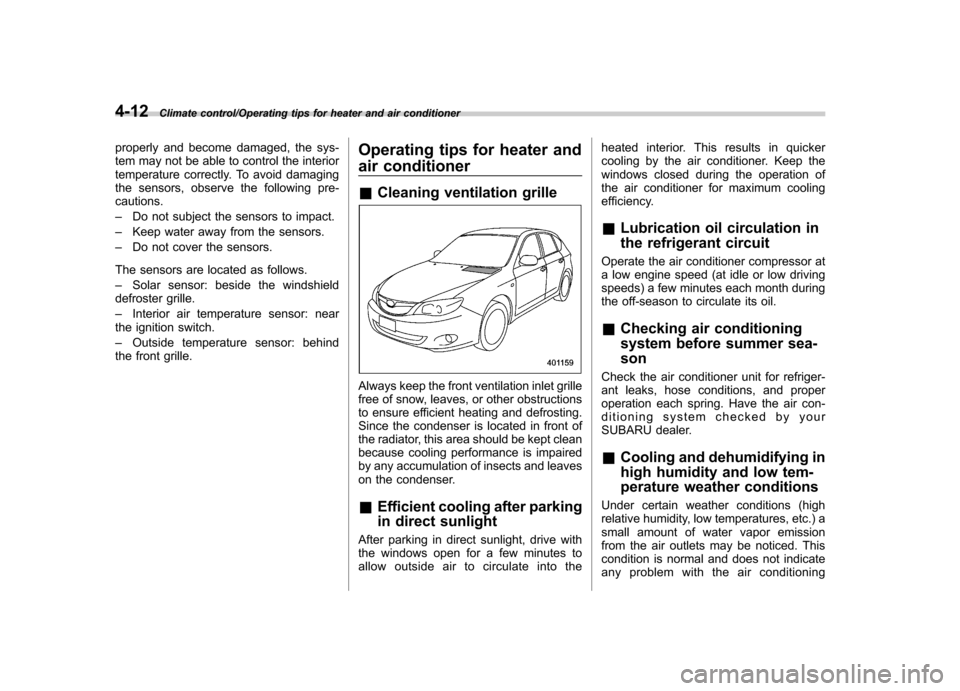
Cleaning ventilation grille
Always keep the front ventilation inlet grille
free of snow, leaves, or other obstructions
to ensure efficient heating and defrosting.
Since the condenser is located in front of
the radiator, this area should be kept clean
because cooling performance is impaired
by any accumulation of insects and leaves
on the condenser. &Efficient cooling after parking
in direct sunlight
After parking in direct sunlight, drive with
the windows open for a few minutes to
allow outside air to circulate into the heated interior. This results in quicker
cooling by the air conditioner. Keep the
windows closed during the operation of
the air conditioner for maximum cooling
efficiency. &
Lubrication oil circulation in
the refrigerant circuit
Operate the air conditioner compressor at
a low engine speed (at idle or low driving
speeds) a few minutes each month during
the off-season to circulate its oil. & Checking air conditioning
system before summer sea-son
Check the air conditioner unit for refriger-
ant leaks, hose conditions, and proper
operation each spring. Have the air con-
ditioning system checked by your
SUBARU dealer. & Cooling and dehumidifying in
high humidity and low tem-
perature weather conditions
Under certain weather conditions (high
relative humidity, low temperatures, etc.) a
small amount of water vapor emission
from the air outlets may be noticed. This
condition is normal and does not indicate
any problem with the air conditioning
Page 178 of 414
system. &Air conditioner compressor
shut-off when engine is
heavily loaded
To improve acceleration and gas mileage,
the air conditioner compressor is designed
to temporarily shut off during air condi-
tioner operation whenever the accelerator
is fully depressed such as during rapid
acceleration or when driving on a steepupgrade. & Refrigerant for your climate
control system
Your air conditioner uses ozone friendly
refrigerant HFC134a. Therefore, the meth-
od of adding, changing or checking the
refrigerant is different from the method for
CFC12 (freon). Consult your SUBARU
dealer for service. Repairs needed as a
result of using the wrong refrigerant are
not covered under warranty. Air filtration system
Replace the filter element according to the
replacement schedule as follows. This
schedule should be followed to maintain
the filter
’s dust collection ability. Under
extremely dusty conditions, the filter
should be replaced more frequently. It is
recommended that you have your filter
checked or replaced by your SUBARU
dealer. For replacement, use only a
genuine SUBARU air filter kit.
Replacement schedule: Every 12 months or 7,500 miles (12,000
km) whichever comes first
CAUTION
Contact your SUBARU dealer if the
following occurs, even if it is not yet
time to change the filter: . Reduction of the airflow through
the vents.
. Windshield gets easily fogged or
misted. NOTE
The filter can influence the air condi-
tioning, heating and defroster perfor-
mance if not properly maintained. &
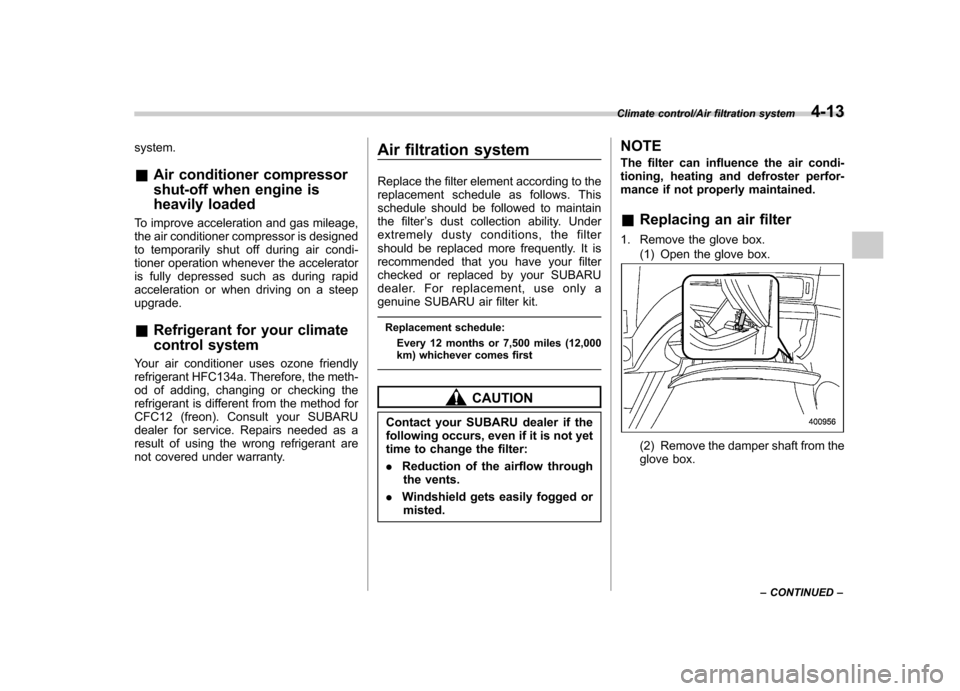
Replacing an air filter
1. Remove the glove box. (1) Open the glove box.
(2) Remove the damper shaft from the
glove box.
Climate control/Air filtration system4-13
– CONTINUED –
Page 217 of 414

5-36Audio/Hands–free system
. When the ignition switch is turned to
the “LOCK ”position during a call, the
call may be disconnected or continued
on the cell phone depending on the
type of cell phone that is used. Note
that operation of the cell phone may be
necessary if the call is continued on the
cell phone. . Do not speak at the same time as the
other party during a call. If you and the
party speak at the same time, it may be
difficult for the other party to hear your
voice and vice versa. This is normal. . The receiver sound volume should
be set as low as possible. Otherwise,
the party you are calling may notice an
undesirable echo sound. . Speak clearly and loudly.
. Your voice may be difficult to be
heard by the party under the following conditions.
–Driving on a rough road.
– Driving at a high speed.
– Driving with a window open.
– When air from the ventilator
blows directly towards the micro-phone. – When the sound coming from the
ventilator is loud.– When the cell phone is too close
to the microphone. .
The sound quality may degrade due
to the influence of the cell phone that is
connected to the system or the circum-
stances of the Bluetooth network. . When another Bluetooth
®device is
simultaneously connected, noise may
be heard in the voice coming from the
hands-free phone. ! Corresponding profiles for the cell phone
. HFP (Hands Free Profile): Ver. 1.0
. OPP (Object Push Profile): Ver. 1.1
& Certification for the Hands-
free system
CAUTION
FCC WARNING
Changes or modifications not ex-
pressly approved by the party re-
sponsible for compliance could void
the user ’s authority to operate the
equipment.
NOTE
This device complies with Part 15 of
the FCC Rules and RSS-Gen of IC
Rules. Operation is subject to the
following two conditions: (1) this de- vice may not cause harmful interfer-
ence, and (2) this device must accept
any interference received, including
interference that may cause undesiredoperation. NOTE
This equipment has been tested and
found to comply with the limits for a
Class B digital device, pursuant to Part
15 of the FCC Rules. These limits are
designed to provide reasonable protec-
tion against harmful interference in a
residential installation. This equipment
may cause harmful interference to
radio communications, if it is not
installed and used in accordance with
the instructions. However, there is no
guarantee that interference will not
occur in a particular installation. If this
equipment does cause harmful inter-
ference to radio or television reception,
which can be determined by turning the
equipment off and on, the user is
encouraged to try to correct the inter-
ference by one or more of the followingmeasures. .
Reorient or relocate the receiving
antenna. . Increase the separation between the
equipment and receiver.. Connect the equipment into an out-
Page 247 of 414

7-4Starting and operating/Fuel
system performance may deteriorate and
the CHECK ENGINE warning light/Mal-
function indicator light may turn on. If this
happens, return to your authorized
SUBARU Dealer for service. If it is
determined that the condition is caused
by the type of fuel used, repairs may not
be covered by your warranty. !Gasoline for cleaner air
Your use of gasoline with detergent
additives will help prevent deposits from
forming in your engine and fuel system.
This helps keep your engine in tune and
your emission control system working
properly, and is a way of doing your part
for cleaner air. If you continuously use a
high quality fuel with the proper detergent
and other additives, you should never
need to add any fuel system cleaning
agents to your fuel tank.
Many gasolines are now blended with
materials called oxygenates. Use of these
fuels can also help keep the air cleaner.
Oxygenated blend fuels, such as MTBE
(Methyl Tertiary Butyl ether) or ethanol
(ethyl or grain alcohol) may be used in
your vehicle, but should contain no more
than 15% MTBE or 10% ethanol for the
proper operation of your SUBARU.
Do not use any gasoline that contains
more than 10% ethanol, including from any pump labeled E15, E30, E50 or E85
(which are only some examples of fuel
containing more than 10% ethanol).
In addition, some gasoline suppliers are
now producing reformulated gasolines,
which are designed to reduce vehicle
emissions. SUBARU approves the use of
reformulated gasoline.
If you are not sure what the fuel contains,
you should ask your service station
operators if their gasolines contain deter-
gents and oxygenates and if they have
been reformulated to reduce vehicle emis-sions.
As additional guidance, only use fuels
suited for your vehicle as explained in the
following description. .
Fuel should be unleaded and have an
octane rating no lower than that specified
in this manual. . Methanol (methyl or wood alcohol) is
sometimes mixed with unleaded gasoline.
Methanol can be used in your vehicle
ONLY if it does not exceed 5% of the fuel
mixture ANDif it is accompanied by
sufficient quantities of the proper cosol-
vents and corrosion inhibitors required to
prevent damage to the fuel system. Do not
use fuel containing methanol EXCEPT
under these conditions. .
If undesirable driveability problems are
experienced and you suspect they may be
fuel related, try a different brand of gaso-
line before seeking service at your
SUBARU dealer. . Fuel system damage or driveability
problems which result from the use of
improper fuel are not covered under the
SUBARU Limited Warranty.
CAUTION
Do not let fuel spill on the exterior
surfaces of the vehicle. Because
fuel may damage the paint, be sure
to wipe off any spilled fuel quickly.
Paint damage caused by spilled fuel
is not covered under the SUBARU
Limited Warranty.
& Fuel filler lid and cap
! Refueling
Only one person should be involved in
refueling. Do not allow others to approach
the area of the vehicle near the fuel filler
pipe while refueling is in progress.
Be sure to observe any other precautions
that are posted at the service station.
Page 254 of 414
an additional four times. If the vehicle fails
to start after the additional attempts, the
remote engine start system will abort and
return to a non-activated state. &Remote start safety features
For safety and security reasons, the
system will fail to start and beep the horn
twice or shut down the engine during
remote start operation if any of the
following conditions occur. . The brake pedal is depressed before
the vehicle ignition switch is turned “on ”.
. The key was already in the ignition
switch.. The engine hood is opened.
. The vehicle ’s engine idle speed has
reached a level over 3,000 rpm.. The alarm is triggered by opening a
door or the rear gate.
NOTE . The security indicator light on the
combination meter will stop flashing
while under remote engine start opera-
tion, but the vehicle is still protected.. If the vehicle is entered during
remote engine start operation, the
system will not record entry in the
alarm history. &
Entering the vehicle while it
is running via remote start
1. Unlock the vehicle doors using the
remote keyless entry system. If the vehi-cle ’s doors are unlocked manually using
the key, the vehicle ’s alarm system will
trigger and the remote engine start system
will turn off. Inserting the key into the
ignition switch and turning it to the “ON ”
position or pressing the unlock button “
”
on the remote keyless entry transmitter
will disarm the alarm system. Refer to“ Alarm system ”F 2-15.
2. Enter the vehicle. Do not depress the
brake pedal.
3. Insert the key into the ignition switch
and turn to the “ON ”position. If the ignition
switch is accidentally turned to the“ START ”position, the system ’s “starter
anti-grind ”feature will prevent the starter
from re-cranking.
4. Depress the brake pedal. The remote
starter disengages, the vehicle ’s power
window features are re-enabled and the
vehicle will operate normally.
& Entering the vehicle follow-
ing remote engine start shut-down
An alarm trigger may occur if the vehicle is
opened by the remote keyless entry transmitter within a few seconds immedi-
ately following remote engine start shut-down. &
Pre-heating or pre-cooling
the interior of the vehicle
Before exiting the vehicle, set the tem-
perature controls to the desired setting
and operation. After the system starts the
vehicle, the heater or air-conditioning will
activate and heat or cool the interior to
your setting. & Service mode
In service mode, the remote start function
is temporarily disabled to prevent the
system from unexpectedly starting the
engine while being serviced. ! To engage the service mode
Turntheignitionswitchtothe “ON ”
position, depress and hold the brake
pedal, then press and release the “
”
button on the remote engine start trans-
mitter three times. The system will pause
for 1 second and then flash the turn signal
lights and honk the horn three times
indicating that the system is in service
mode. When attempting to activate the
remote start system while in service
mode, the turn signal lights will flash and
the horn will honk two times and will not
Starting and operating/Remote engine start system (dealer option)7-11
– CONTINUED –
Page 270 of 414

Electronic Brake Force Dis-
tribution (EBD) system
The EBD system maximizes the effective-
ness of the brakes by allowing the rear
brakes to supply a greater proportion of
the braking force. It functions by adjusting
the distribution of braking force to the rear
wheels in accordance with the vehicle’s
loading condition and speed.
The EBD system is an integral part of the
ABS system and uses some of the ABSsystem ’s components to perform its func-
tion of optimizing the distribution of brak-
ing force. If any of the ABS components
used by the EBD system malfunction, the
EBD system also stops working.
When the EBD system is operating, you
may hear a chattering noise or feel a slight
vibration in the brake pedal. This is normal
and does not indicate a malfunction. &
Steps to take if EBD system malfunctions
If a malfunction occurs in the EBD system,
the system stops working and the brake
system warning light and ABS warning
light illuminate simultaneously.
The EBD system may be malfunctioning if
the brake system warning light and ABS
warning light illuminate simultaneously
during driving.
Even if the EBD system malfunctions, the
conventional braking system will still func-
tion. However, the rear wheels will be
more prone to locking when the brakes
are applied harder than usual and thevehicle ’s motion may therefore become
somewhat harder to control.
If the brake system warning light and ABS warning light illuminate simultaneously,
take the following steps.
1. Stop the vehicle in the nearest safe,
flat location.
2. Shut down the engine, apply the
parking brake, and then restart it.
3. Release the parking brake. If both
warning lights turn off, the EBD system
may be malfunctioning. Drive carefully to
the nearest SUBARU dealer and have the
system inspected.
4. If both warning lights illuminate again
and remain illuminated after the engine
has been restarted, shut down the engine
again, apply the parking brake, and check
the brake fluid level. Refer to
“Brake fluid ”
F 11-18.
5. If the brake fluid level is not below the“ MIN ”mark, the EBD system may be
malfunctioning. Drive carefully to the
nearest SUBARU dealer and have the
system inspected.
6. If the brake fluid level is below the “ MIN ”mark, DO NOT drive the vehicle.
Instead, have the vehicle towed to the
nearest SUBARU dealer for repair.
WARNING
. Driving with the brake system
warning light illuminated is dan-
Starting and operating/Electronic Brake Force Distribution (EBD) system7-27
– CONTINUED –
Page 271 of 414

7-28Starting and operating/Vehicle Dynamics Control system
gerous. This indicates your brake
system may not be working
properly. If the light remains
illuminated, have the brakes in-
spected by a SUBARU dealer
immediately.
. If at all in doubt about whether
the brakes are operating prop-
erly, do not drive the vehicle.
Have your vehicle towed to the
nearest SUBARU dealer for re-
pair. Vehicle Dynamics Control system
WARNING
Always use the utmost care in driving –overconfidence because
you are driving with a Vehicle Dy-
namics Control system equipped
vehicle could easily lead to a ser-
ious accident.
CAUTION
. Even if your vehicle is equipped
with Vehicle Dynamics Control
system, winter tires should be
used when driving on snow-cov-
ered or icy roads; in addition,
vehicle speed should be reduced
considerably. Simply having a
Vehicle Dynamics Control sys-
tem does not guarantee that the
vehicle will be able to avoid
accidents in any situation.
. Activation of the Vehicle Dy-
namics Control system is an
indication that the road being
travelled on has a slippery sur-
face; since having Vehicle Dy- namics Control is no guarantee
that full vehicle control will be
maintained at all times and under
all conditions, its activation
should be seen as a sign that
the speed of the vehicle should
be reduced considerably.
. Whenever suspension compo-
nents, steering components, or
an axle are removed from a
vehicle, have an inspection of
that system performed by an
authorized SUBARU dealer.
. The following precautions should
be observed in order to ensure
that the Vehicle Dynamics Con-
trol system is operating properly: – All four wheels should be
fitted with tires of the same
size, type, and brand. Further-
more, the amount of wear
should be the same for all
four tires.
– Keep the tire pressure at the
proper level as shown on the
vehicle placard attached to
the driver ’s side door pillar.
– Use only the specified tem-
porary spare tire to replace a
flat tire. With a temporary
spare tire, the effectiveness
Page 276 of 414

low pressure threshold, the low tire
pressure warning light should turn
off a few minutes later.
If this light still illuminates while
driving after adjusting the tire pres-
sure, a tire may have significant
damage and a fast leak that causes
the tire to lose air rapidly. If you have
a flat tire, replace it with a spare tire
as soon as possible.
When a spare tire is mounted or a
wheel rim is replaced without the
original pressure sensor/transmitter
being transferred, the low tire pres-
sure warning light will illuminate
steadily after blinking for approxi-
mately one minute. This indicates
the TPMS is unable to monitor all
four road wheels. Contact your
SUBARU dealer as soon as possible
for tire and sensor replacement and/
or system resetting.
Do not inject any tire liquid or
aerosol tire sealant into the tires,
as this may cause a malfunction of
the tire pressure sensors. If the light
illuminates steadily after blinking for
approximately one minute, promptly
contact a SUBARU dealer to have
the system inspected.CAUTION
. Do not place metal film or any
metal parts in the cargo area/
trunk. This may cause poor re-
ception of the signals from the
tire pressure sensors, and the
tire pressure monitoring system
will not function properly.
. FCC WARNING
Changes or modifications not
expressly approved by the party
responsible for compliance
could void the user ’s authority
to operate the equipment.
NOTE
This device complies with Part 15 of
the FCC Rules and RSS-Gen of IC
Rules. Operation is subject to the
following two conditions: (1) this de-
vice may not cause harmful interfer-
ence, and (2) this device must accept
any interference received, including
interference that may cause undesiredoperation. Parking your vehicle &
Parking brake
To set the parking brake, depress the
brake pedal firmly and hold it down until
the parking brake lever is fully pulled up.
To release the parking brake, pull the lever
up slightly, press the release button, then
lower the lever while keeping the button pressed.
When the parking brake is set while the
engine is running, the parking brake
warning light illuminates. After starting
the vehicle, be sure that the warning light
has turned off before the vehicle is driven.
Refer to “Parking brake warning ”F 3-19.
Starting and operating/Parking your vehicle7-33
– CONTINUED –