battery replacement SUBARU IMPREZA WRX 2014 4.G Owners Manual
[x] Cancel search | Manufacturer: SUBARU, Model Year: 2014, Model line: IMPREZA WRX, Model: SUBARU IMPREZA WRX 2014 4.GPages: 414, PDF Size: 14.22 MB
Page 86 of 414
Keys..................................................................... 2-2
Key number plate ................................................ 2-2
Immobilizer .......................................................... 2-2
Security ID plate .................................................. 2-3
Security indicator light ........................................ 2-3
Key replacement ................................................. 2-3
Door locks ........................................................... 2-4
Locking and unlocking from the outside .. ............ 2-4
Locking and unlocking from the inside ................ 2-5
Battery drainage prevention function ................... 2-5
Power door locking switches ............................. 2-6
Key lock-in prevention function ........................... 2-7
Remote keyless entry system ............................ 2-7
Locking the doors ............................................... 2-9
Unlocking the doors ............................................ 2-9
Opening the trunk lid/unlocking rear gate ............ 2-9
Vehicle finder function ........................................ 2-10
Sounding a panic alarm ...................................... 2-10
Selecting audible signal operation ...................... 2-10
Replacing the battery ......................................... 2-11
Replacing lost transmitters ................................. 2-11
Alarm system ..................................................... 2-15
System operation ............................................... 2-15 Activating and deactivating the alarm system
..... 2-15
If you have accidentally triggered the alarm system ............................................................ 2-16
Arming the system ............................................ 2-16
Disarming the system ........................................ 2-17
Valet mode ........................................................ 2-17
Passive arming .................................................. 2-18
Tripped sensor identification .............................. 2-19
Shock sensors (dealer option).. .......................... 2-19
Child safety locks .............................................. 2-20
Windows ............................................................. 2-20
Power windows ................................................. 2-20
Trunk lid (4-door) ............................................... 2-23
To open and close the trunk lid from outside . ..... 2-23
To open the trunk lid from inside. ....................... 2-23
To lock and unlock the trunk lid release lever ................................................................ 2-24
Internal trunk lid release handle ......................... 2-24
Rear gate (5-door) .............................................. 2-26
Moonroof (if equipped) ...................................... 2-27
Moonroof switches ............................................ 2-28
Sun shade ......................................................... 2-29 Keys and doors
2
Page 96 of 414
&Replacing the battery
CAUTION
. Do not let dust, oil or water get on
or in the transmitter when repla-
cing the battery.
. Be careful not to damage the
printed circuit board in the trans-
mitter when replacing the battery.
. Be careful not to allow children to
touch the battery and any re-
moved parts; children could
swallow them.
. There is a danger of explosion if
an incorrect replacement battery
is used. Replace only with the
same or equivalent type of bat-
tery.
. Batteries should not be exposed
to excessive heat such as sun-
shine, fire or the like.
When the transmitter battery begins to get
weak, transmitter range will begin to
decrease. Replace the battery as soon
as possible. To replace the battery:
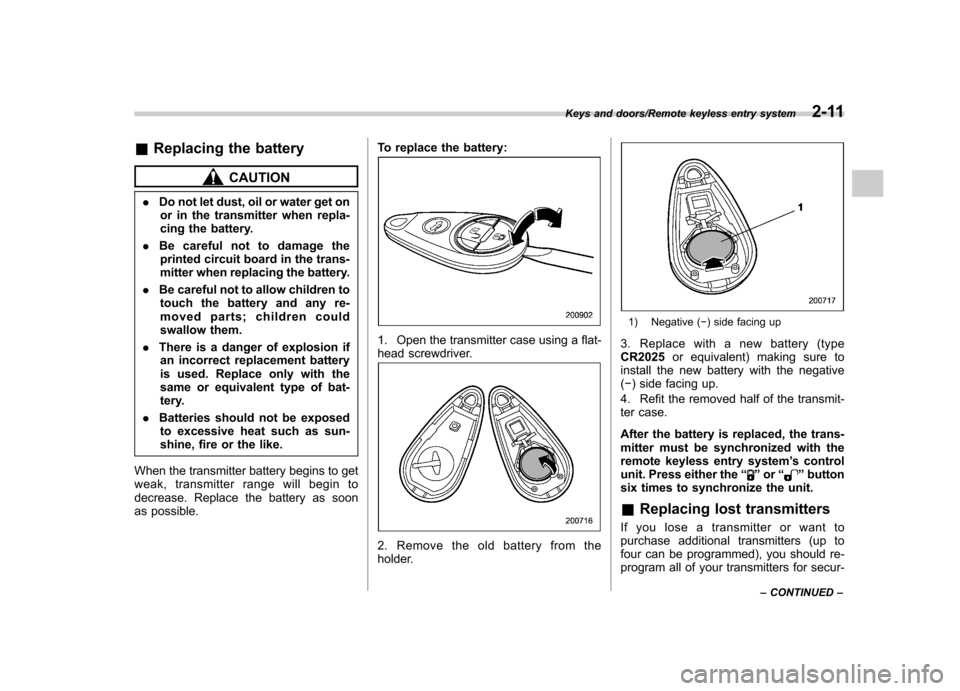
1. Open the transmitter case using a flat-
head screwdriver.
2. Remove the old battery from the
holder.
1) Negative (
�) side facing up
3. Replace with a new battery (type CR2025 or equivalent) making sure to
install the new battery with the negative( � ) side facing up.
4. Refit the removed half of the transmit-
ter case.
After the battery is replaced, the trans-
mitter must be synchronized with the
remote keyless entry system ’s control
unit. Press either the “
”or “”button
six times to synchronize the unit. & Replacing lost transmitters
If you lose a transmitter or want to
purchase additional transmitters (up to
four can be programmed), you should re-
program all of your transmitters for secur-
Keys and doors/Remote keyless entry system2-11
– CONTINUED –
Page 106 of 414
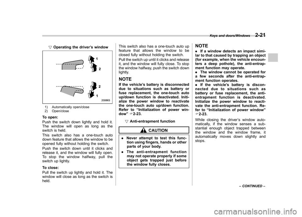
!Operating the driver ’s window
1) Automatically open/close
2) Open/close
To open:
Push the switch down lightly and hold it.
The window will open as long as the
switch is held.
This switch also has a one-touch auto
down feature that allows the window to be
opened fully without holding the switch.
Push the switch down until it clicks and
release it, and the window will fully open.
To stop the window halfway, pull the
switch up lightly.
To close:
Pull the switch up lightly and hold it. The
window will close as long as the switch isheld. This switch also has a one-touch auto up
feature that allows the window to be
closed fully without holding the switch.
Pull the switch up until it clicks and release
it, and the window will fully close. To stop
the window halfway, push the switch down
lightly.
NOTE
If the vehicle ’s battery is disconnected
due to situations such as battery or
fuse replacement, the one-touch auto
up/down function is deactivated. Initi-
alize the power window to reactivate
the one-touch auto up/down function.
Refer to “Initialization of power win-
dow ”F 2-23.
! Anti-entrapment function
CAUTION
. Never attempt to test this func-
tion using fingers, hands or other
parts of your body.
. The anti-entrapment function
may not operate properly if some
object gets trapped just before
the window fully closes. NOTE .
If a window detects an impact simi-
lar to that caused by trapping an object
(for example, when the vehicle encoun-
ters a deep pothole), the anti-entrap-
ment function may operate.. The window cannot be operated for
a few seconds after the anti-entrap-
ment function operates.. If the vehicle ’s battery is discon-
nected due to situations such as
battery or fuse replacement, the anti-
entrapment functi on is deactivated.
Initialize the power window to reacti-
vate the anti-entrapment function. Re-
fer to “Initialization of power window ”
F 2-23.
While closing the driver ’s window auto-
matically, if the window senses a sub-
stantial enough object trapped between
the window and the window frame, it
automatically moves down slightly andstops.
Keys and doors/Windows2-21
– CONTINUED –
Page 108 of 414
!Initialization of power window
If the vehicle ’s battery is disconnected due
to situations such as battery or fuse
replacement, the following functions aredeactivated. . One-touch auto up/down function
. Anti-entrapment function
Initialize the power window using the
following procedure to reactivate thesefunctions.
1. Close the driver ’s door.
2. Turn the ignition switch to the “ON ”
position.
3. Open the driver ’s side window halfway
by pushing down the power window switch.
4. Pull up the power window switch and
close the window completely. Continue
pulling up the switch for approximately 1
second after the window is closed com-
pletely. Trunk lid (4-door)
WARNING
. To prevent dangerous exhaust
gas from entering the vehicle,
always keep the trunk lid closed
while driving.
. Help prevent children, adults or
animals from locking themselves
in the trunk. On hot or sunny
days, the temperature in the
trunk could quickly become high
enough to cause death or serious
heat-related injuries including
brain damage to anyone locked
inside, particularly for small chil-dren.
. When leaving the vehicle, either
close all windows and lock all
doors. Also make certain that the
trunk is closed. &
To open and close the trunk
lid from outside
The trunk lid can be opened using the
remote keyless entry system. Refer to“ Remote keyless entry system ”F 2-7.
To close the trunk lid, lightly press the
trunk lid down until the latch engages.
NOTE
Do not leave your valuables in the
trunk when you leave your vehicle. & To open the trunk lid from inside
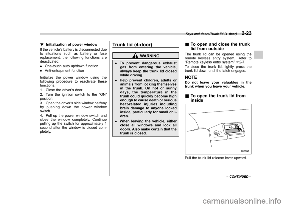
Pull the trunk lid release lever upward.
Keys and doors/Trunk lid (4 –door)2-23
– CONTINUED –
Page 124 of 414
NOTE
If the connection between the combina-
tion meter and battery is broken for any
reason such as vehicle maintenance or
fuse replacement, the data recorded on
the trip meter will be lost. &Tachometer
The tachometer shows the engine speed
in thousands of revolutions per minute.
CAUTION
Do not operate the engine with the
pointer of the tachometer in the red
zone. This may cause severe da-
mage to the engine. &
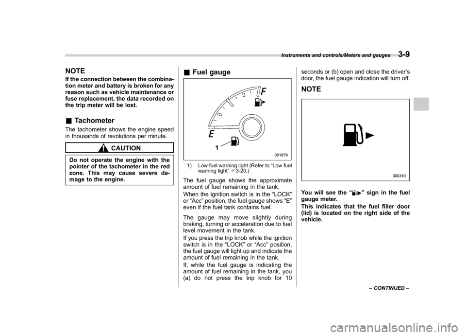
Fuel gauge
1) Low fuel warning light (Refer to “Low fuel
warning light ”F 3-20.)
The fuel gauge shows the approximate
amount of fuel remaining in the tank.
When the ignition switch is in the “LOCK ”
or “Acc ”position, the fuel gauge shows “E ”
even if the fuel tank contains fuel.
The gauge may move slightly during
braking, turning or acceleration due to fuel
level movement in the tank.
If you press the trip knob while the ignition
switch is in the “LOCK ”or “Acc ”position,
the fuel gauge will light up and indicate the
amount of fuel remaining in the tank.
If, while the fuel gauge is indicating the
amount of fuel remaining in the tank, you
(a) do not press the trip knob for 10 seconds or (b) open and close the driver
’s
door, the fuel gauge indication will turn off.
NOTE
You will see the “”sign in the fuel
gauge meter.
This indicates that the fuel filler door
(lid) is located on the right side of thevehicle.
Instruments and controls/Meters and gauges3-9
– CONTINUED –
Page 133 of 414
3-18Instruments and controls/Warning and indicator lights
sure warning light will illuminate
steadily after blinking for approxi-
mately one minute. This indicates
the TPMS is unable to monitor all
four road wheels. Contact your
SUBARU dealer as soon as possible
for tire and sensor replacement and/
or system resetting.
If the light illuminates steadily after
blinking for approximately one min-
ute, promptly contact a SUBARU
dealer to have the system inspected.
CAUTION
The tire pressure monitoring system
is NOT a substitute for manually
checking tire pressure. The tire
pressure should be checked peri-
odically (at least monthly) using a
tire gauge. After any change to tire
pressure(s), the tire pressure mon-
itoring system will not re-check tire
inflation pressures until the vehicle
is first driven more than 20 mph (32
km/h). After adjusting the tire pres-
sures, increase the vehicle speed to
at least 20 mph (32 km/h) to start the
TPMS re-checking of the tire infla-
tion pressures. If the tire pressures
are now above the severe low
pressure threshold, the low tire pressure warning light should turn
off a few minutes later. Therefore, be
sure to install the specified size for
the front and rear tires.
& ABS warning light
CAUTION
. If any of the following conditions
occur, we recommend that you
have the ABS system repaired at
the first available opportunity by
your SUBARU dealer. – The warning light does not
illuminate when the ignition
switch is turned to the “ON ”
position.
– The warning light illuminates
when the ignition switch is
turned to the “ON ”position,
but it does not turn off even
when the vehicle speed ex-
ceeds approximately 8 mph
(12 km/h).
– The warning light illuminates
during driving.
. When the warning light is on (and
the brake system warning light is
off), the ABS function shuts
down. However, the conventional brake system continues to oper-
ate normally.
With a vehicle equipped with an EBD
system, the ABS warning light illuminates
together with the brake system warning
light if the EBD system malfunctions. For
further details of the EBD system mal-
function warning, refer to “Electronic
Brake Force Distribution (EBD) systemwarning ”F 3-19.
NOTE
If the warning light behavior is as
described in the following conditions,
the ABS system may be considerednormal. . The warning light illuminates right
after the engine is started but turns off
immediately, remaining off. . The warning light remains illumi-
nated after the engine has been started,
but it turns off when the vehicle speed
reaches approximately 8 mph (12km/h).. The warning light illuminates during
driving, but it turns off immediately and
remains off.
When driving with an insufficient battery
voltage such as when the engine is jump
started, the ABS warning light may illumi-
nate. This is due to the low battery voltage
Page 144 of 414
when the battery voltage is discon-
nected and then reconnected for bat-
tery replacement or fuse replacement.Light control switch
The light control switch operates when the
key is inserted into the ignition switch.
Regardless of the position of the light
control switch, the illuminated lights are
turned off when the key is removed from
the ignition switch. NOTE
Even if the key is removed from the
ignition switch, the lights can be illu-
minated by operating the light control
switch from
“OFF ”to the “
”or “”
position. In this case, if the driver ’s
door is opened, a chirp sound will
inform the driver that the lights areilluminated.
CAUTION
. Use of any lights for a long period
of time while the engine is not
running can cause the battery todischarge.
. Before leaving the vehicle, make
sure that the light control switch
is turned to the “OFF ”position. If
the vehicle is left unattended for
a long time with the light control
switch set to a position otherthan “OFF ”, the battery may be discharged.
& Headlights
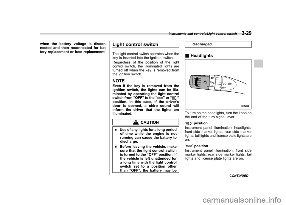
To turn on the headlights, turn the knob on
the end of the turn signal lever. “
”position
Instrument panel illumination, headlights,
front side marker lights, rear side marker
lights, tail lights and license plate lights areon. “
” position
Instrument panel illumination, front side
marker lights, rear side marker lights, tail
lights and license plate lights are on.
Instruments and controls/Light control switch3-29
– CONTINUED –
Page 256 of 414
an incorrect replacement battery
is used. Replace only with the
same or equivalent type of bat-
tery.
. Batteries should not be exposed
to excessive heat such as sun-
shine, fire or the like.
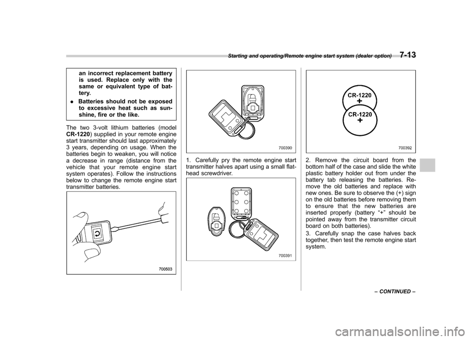
The two 3-volt lithium batteries (modelCR-1220 ) supplied in your remote engine
start transmitter should last approximately
3 years, depending on usage. When the
batteries begin to weaken, you will notice
a decrease in range (distance from the
vehicle that your remote engine start
system operates). Follow the instructions
below to change the remote engine start
transmitter batteries.
1. Carefully pry the remote engine start
transmitter halves apart using a small flat-
head screwdriver.2. Remove the circuit board from the
bottom half of the case and slide the white
plastic battery holder out from under the
battery tab releasing the batteries. Re-
move the old batteries and replace with
new ones. Be sure to observe the (+) sign
on the old batteries before removing them
to ensure that the new batteries are
inserted properly (battery “+ ” should be
pointed away from the transmitter circuit
board on both batteries).
3. Carefully snap the case halves back
together, then test the remote engine startsystem.
Starting and operating/Remote engine start system (dealer option)7-13
– CONTINUED –
Page 321 of 414
Maintenance and serviceTire replacement .............................................. 11-29
Wheel replacement ........................................... 11-30
Aluminum wheels ............................................. 11-31
Windshield washer fluid .................................. 11-31
Replacement of wiper blades .......................... 11-32
Windshield wiper blade assembly ..................... 11-33
Windshield wiper blade rubber (type A and type B) .................................................................. 11-34
Rear window wiper blade assembly (5-door models). ......................................................... 11-35
Rear window wiper blade rubber (5-door models). ......................................................... 11-35
Battery. .............................................................. 11-37
Fuses ................................................................ 11-38 Installation of accessories
.............................. 11-39
Replacing bulbs ............................................... 11-39
Headlights (models with HID headlights) ........... 11-39
Headlights (models without HID headlights) ...... 11-40
Front turn signal light ...................................... 11-42
Front fog light (if equipped) .............................. 11-42
Rear combination lights ................................... 11-43
Backup light (5-door) ....................................... 11-45
License plate light ........................................... 11-46
Map light ......................................................... 11-46
Dome light and cargo area light ....................... 11-47
Trunk light ....................................................... 11-47
High-mounted stop light (4-door) ... ................... 11-48
Other bulbs ..................................................... 11-48
Page 322 of 414
Maintenance schedule
The scheduled maintenance items re-
quired to be serviced at regular intervals
are shown in the“Warranty and Main-
tenance Booklet ”.
For details of your maintenance schedule,
read the separate “Warranty and Main-
tenance Booklet ”. Maintenance precautions
When maintenance and service are re-
quired, it is recommended that all work be
done by an authorized SUBARU dealer.
If you perform maintenance and service
by yourself, you should familiarize yourself
with the information provided in this
section on general maintenance and
service for your SUBARU.
Incorrect or incomplete service could
cause improper or unsafe vehicle opera-
tion. Any problems caused by improper
maintenance and service performed by
you are not eligible for warranty coverage.
WARNING
. Testing of an All-Wheel Drive
model must NEVER be per-
formed on a single two-wheel
dynamometer or similar appara-
tus. Attempting to do so will
result in transmission damage
and in uncontrolled vehicle
movement and may cause an
accident or injuries to persons
nearby.
. Always select a safe area when
performing maintenance on yourvehicle. .
Always be very careful to avoid
injury when working on the vehi-
cle. Remember that some of the
materials in the vehicle may be
hazardous if improperly used or
handled, for example, batteryacid.
. Your vehicle should only be ser-
viced by persons fully competent
to do so. Serious personal injury
may result to persons not experi-
enced in servicing vehicles.
. Always use the proper tools and
make certain that they are wellmaintained.
. Never get under the vehicle sup-
ported only by a jack. Always use
safety stands to support thevehicle.
. Never keep the engine running in
a poorly ventilated area, such as
a garage or other closed areas.
. Do not smoke or allow open
flames around the fuel or battery.
This will cause a fire.
. Because the fuel system is under
pressure, replacement of the fuel
filter should be performed only
by your SUBARU dealer.
. Wear adequate eye protection to
Maintenance and service/Maintenance schedule11-3
– CONTINUED –