engine coolant SUBARU IMPREZA WRX STI 2011 Owners Manual
[x] Cancel search | Manufacturer: SUBARU, Model Year: 2011, Model line: IMPREZA WRX STI, Model: SUBARU IMPREZA WRX STI 2011Pages: 459, PDF Size: 6.66 MB
Page 28 of 459
Black plate (26,1)
北米Model "A1110BE-C" EDITED: 2010/ 12/ 17
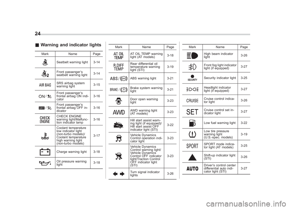
24& Warning and indicator lights
Mark Name Page
Seatbelt warning light 3-14Front passenger’s
seatbelt warning light 3-14SRS airbag system
warning light3-15
/
Front passenger
’s
frontal airbag ON indi-
cator 3-16
/
Front passenger
’s
frontal airbag OFF in-
dicator 3-16CHECK ENGINE
warning light/Malfunc-
tion indicator lamp3-16Coolant temperature
low indicator light
(non-turbo models)/
Coolant temperature
high warning light
(non-turbo models)3-17Charge warning light 3-18Oil pressure warning
light
3-18Mark Name Page
AT OIL TEMP warning
light (AT models)
3-18Rear differential oil
temperature warning
light (STI)3-19ABS warning light 3-21Brake system warning
light
3-21Door open warning
light3-23AWD warning light
(AT models)3-23Hill start assist warn-
ing light (if equipped)/
Hill start assist OFF
indicator light (STI)3-22Vehicle Dynamics
Control operation indi-
cator light
3-23Vehicle Dynamics
Control warning light/
Vehicle Dynamics
Control OFF indicator
light/Traction Control
OFF indicator light
(STI)3-23Turn signal indicator
lights
3-26Mark Name Page
High beam indicator
light
3-26Front fog light indicator
light (if equipped)3-27Security indicator light 3-25Headlight indicator
light (if equipped)3-27Cruise control indica-
tor light
3-26Cruise control set in-
dicator light3-27Low fuel warning light 3-22Low tire pressure
warning light
(U.S.-spec. models)3-19SPORT mode indica-
tor light (AT models)
3-25Shift-up indicator light
(STI)
3-26Driver
’s control center
differential auto indi-
cator light (STI) 3-27
Page 121 of 459
Black plate (5,1)
北米Model "A1110BE-C" EDITED: 2010/ 11/ 17
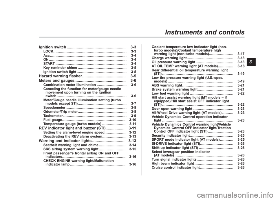
Ignition switch ..................................................... 3-3
LOCK.................................................................. 3-3
Acc..................................................................... 3-4
ON...................................................................... 3-4
START ................................................................ 3-4
Key reminder chime ............................................ 3-5
Ignition switch light ............................................. 3-5
Hazard warning flasher ....................................... 3-5
Meters and gauges. ............................................. 3-6
Combination meter illumination ........................... 3-6
Canceling the function for meter/gauge needle movement upon turning on the ignition
switch ............................................................... 3-6
Meter/Gauge needle illumination setting (turbo models except STI) ............................................ 3-7
Speedometer ....................................................... 3-8
Odometer/Trip meter ............................................ 3-8
Tachometer ......................................................... 3-9
Fuel gauge ......................................................... 3-10
Temperature gauge (turbo models) ..................... 3-11
REV indicator light and buzzer (STI). ................ 3-11
Setting the alarm-level engine speed ................... 3-12
Deactivating the REV alarm system ..................... 3-13
Warning and indicator lights............................. 3-13
Seatbelt warning light and chime ........................ 3-14
SRS airbag system warning light ........................ 3-15
Front passenger ’s frontal airbag ON and OFF
indicators ......................................................... 3-16
CHECK ENGINE warning light/Malfunction indicator lamp .................................................. 3-16 Coolant temperature low indicator light (non-
turbo models)/Coolant temperature high
warning light (non-turbo models) ...................... 3-17
Charge warning light .......................................... 3-18
Oil pressure warning light .................................. 3-18
AT OIL TEMP warning light (AT models) .............. 3-18
Rear differential oil temperature warning light (STI) ................................................................ 3-19
Low tire pressure warning light (U.S.-spec. models) ........................................................... 3-19
ABS warning light .............................................. 3-21
Brake system warning light ................................ 3-21
Low fuel warning light ....................................... 3-22
Hill start assist warning light (MT models –if
equipped)/Hill start assist OFF indicator light
(STI) ................................................................ 3-22
Door open warning light .................................... 3-23
All-Wheel Drive warning light (AT models) ..... ..... 3-23
Vehicle Dynamics Control operation indicator light ................................................................ 3-23
Vehicle Dynamics Control warning light/Vehicle Dynamics Control OFF indicator light/Traction
Control OFF indicator light (STI) ....................... 3-23
Security indicator light ....................................... 3-25
SPORT mode indicator light (AT models) ............ 3-25
SI-DRIVE indicator light (STI) .............................. 3-26
Shift-up indicator light (STI) ............................... 3-26
Select lever/gear position indicator (AT models) ..................................................... 3-26
Turn signal indicator lights ................................. 3-26
High beam indicator light ................................... 3-26
Cruise control indicator light .............................. 3-26
Instruments and controls
3
Page 131 of 459
Black plate (133,1)
北米Model "A1110BE-C" EDITED: 2010/ 12/ 17
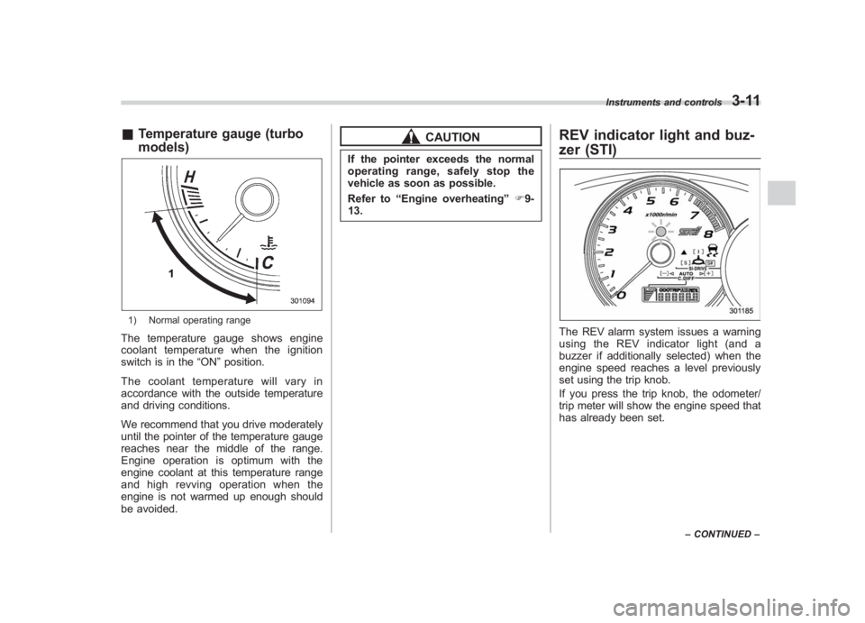
& Temperature gauge (turbo
models)1) Normal operating rangeThe temperature gauge shows engine
coolant temperature when the ignition
switch is in the “ON”position.
The coolant temperature will vary in
accordance with the outside temperature
and driving conditions.
We recommend that you drive moderately
until the pointer of the temperature gauge
reaches near the middle of the range.
Engine operation is optimum with the
engine coolant at this temperature range
and high revving operation when the
engine is not warmed up enough should
be avoided.
CAUTION
If the pointer exceeds the normal
operating range, safely stop the
vehicle as soon as possible.
Refer to “Engine overheating ”F9-
13.
REV indicator light and buz-
zer (STI)The REV alarm system issues a warning
using the REV indicator light (and a
buzzer if additionally selected) when the
engine speed reaches a level previously
set using the trip knob.
If you press the trip knob, the odometer/
trip meter will show the engine speed that
has already been set.
Instruments and controls
3-11
– CONTINUED –
3
Page 133 of 459
Black plate (135,1)
北米Model "A1110BE-C" EDITED: 2010/ 12/ 17
to OFF, OFF to ON, or the vehicle starts
moving before the setting procedure is
finished.
. Setting the speed is impossible
when the vehicle is moving.
. The set engine speed may differ
from the engine speed shown by the
tachometer. Use the engine speed
shown by the tachometer as a rough
guide.
. If the setting operation is performed
with the engine switch turned off, the
REV indicator light turns off and the
setting operation is aborted when you
have stopped the setting operation for
approximately 10 seconds.
. If the setting operation is performed
with the engine switch turned off, the
REV indicator light turns off and the
setting operation is aborted when you
open and close the driver ’s door.& Deactivating the REV alarm
systemTo deactivate the REV indicator light and
buzzer functions of the REV alarm system,
set the thousands place of the alarm-level
engine speed to “–”.
Warning and indicator lightsSeveral of the warning and indicator lights
illuminate momentarily and then turn off
when the ignition switch is initially turned
to the “ON”position. This permits check-
ing the operation of the bulbs.
Apply the parking brake and turn the
ignition switch to the “ON”position. For
the system check, the following lights
illuminate and turn off after several sec-
onds or after the engine has started:: Seatbelt warning light (The seatbelt warning light turns off
only when the driver fastens the
seatbelt.): Front passenger ’s seatbelt warning
light
(The seatbelt warning light turns off
only when the front seat passenger
fastens the seatbelt.): SRS airbag system warning light
ON /
: Front passenger ’s frontal airbag
ON indicator light
/
: Front passenger ’s frontal airbag
OFF indicator light
: CHECK ENGINE warning light/Mal- function indicator lamp
: Coolant temperature high warning light(non-turbo models): Charge warning light: Oil pressure warning light: AT OIL TEMP warning light (AT models): Rear differential oil temperature warn-ing light (STI): Low tire pressure warning light (U.S.- spec. models)/
: ABS warning light
/
: Brake system warning light
: Low fuel warning light: Hill start assist warning light (MT models –if equipped)/Hill start assist
OFF indicator light (STI): Door open warning light: AWD warning light (AT models): Vehicle Dynamics Control operation indicator light: Vehicle Dynamics Control warning light/Vehicle Dynamics Control OFF
indicator light/Traction Control OFF
indicator light (STI)
Instruments and controls
3-13
–CONTINUED –
3
Page 137 of 459
Black plate (139,1)
北米Model "A1110BE-C" EDITED: 2010/ 12/ 17
NOTEThis light also illuminates when the fuel
filler cap is not tightened until it clicks.
If you have recently refueled your vehicle,
the cause of the CHECK ENGINE warning
light/malfunction indicator lamp illuminat-
ing could be a loose or missing fuel filler
cap. Remove the cap and retighten it until
it clicks. Make sure nothing is interfering
with the sealing of the cap. Tightening the
cap will not make the CHECK ENGINE
warning light turn off immediately. It may
take several driving trips. If the light does
not turn off, take your vehicle to your
authorized SUBARU dealer immediately.
! If the light is blinking
If the light is blinking while driving, an
engine misfire condition has been de-
tected which may damage the emission
control system.
To prevent serious damage to the emis-
sion control system, you should do the
following.
. Reduce vehicle speed.
. Avoid hard acceleration.
. Avoid steep uphill grades.
. Reduce the amount of cargo, if possi-
ble. The CHECK ENGINE warning light may
stop blinking and illuminate steadily after
several driving trips. You should have your
vehicle checked by an authorized
SUBARU dealer immediately.
&
Coolant temperature
low indicator light (non-
turbo models)/Coolant
temperature high warn-
ing light (non-turbo
models)
CAUTION
.
After turning the ignition switch
to the “ON ”position, if this
indicator light/warning light be-
haves in any of the following
ways, the electrical system may
be malfunctioning. Contact your
SUBARU dealer immediately for
an inspection.
– It remains blinking in RED.
– It remains illuminated in RED
for more than 2 seconds.
– It remains blinking in RED and
BLUE alternately.
. While driving, if this indicator
light/warning light behaves in
any of the following ways, take the specified appropriate mea-
sure listed below.
–
Blinking or illuminated in
RED:
Safely stop the vehicle as
soon as possible, and refer
to the emergency steps to
take in the case of engine
overheating. After that, have
the system checked by your
nearest SUBARU dealer. Refer
to “Engine overheating ”F9-
13.
– Blinking in RED and BLUE
alternately:
The electrical system may be
malfunctioning. Contact your
SUBARU dealer for an inspec-
tion.
This coolant temperature low indicator
light/coolant temperature high warning
light has the following three functions.
. Illumination in BLUEindicates insuffi-
cient warming up of the engine
. Blinking in REDindicates that the
engine is close to overheating
. Illumination in REDindicates overheat-
ing condition of the engine
For a system check, this indicator light/
warning light illuminates in REDfor
Instruments and controls
3-17
–CONTINUED –
3
Page 138 of 459
Black plate (140,1)
北米Model "A1110BE-C" EDITED: 2010/ 12/ 17
3-18
Instruments and controls
approximately 2 seconds when the igni-
tion switch is turned to the “ON”position.
After that, this indicator light/warning light
changes to BLUEand maintains illumina-
tion in BLUE. This BLUEilluminated light
turns off when the engine is warmed up
sufficiently.
If the engine coolant temperature in-
creases over the specified range, the
indicator light/warning light blinks in
RED . At this time, the engine is close to
overheating.
If the engine coolant temperature in-
creases further, the indicator light/warning
light illuminates in REDcontinuously. At
this time, the engine may be overheating.
When the indicator light/warning light
blinks in REDor illuminates in RED, safely
stop the vehicle as soon as possible, and
refer to the emergency steps to take in the
case of engine overheating. Refer to
“Engine overheating ”F 9-13. After that,
have the system checked by your nearest
SUBARU dealer.
Also, if the indicator light/warning light
often blinks in RED, the electrical system
may be malfunctioning. Contact your
SUBARU dealer for an inspection.
NOTEIf the engine is restarted after a certain
driving condition, this indicator light/
warning light may illuminate in RED.
However, this is not a malfunction if the
indicator light/warning light turns off
after a short time.&
Charge warning light
If this light illuminates when the engine is
running, it may indicate that the charging
system is not working properly.
If the light illuminates while driving or does
not turn off after the engine starts, stop the
engine at the first safe opportunity and
check the alternator belt. If the belt is
loose, broken or if the belt is in good
condition but the light remains illuminated,
contact your nearest SUBARU dealer
immediately.&
Oil pressure warning
light
If this light illuminates when the engine is
running, it may indicate that the engine oil
pressure is low and the lubricating system
is not working properly.
If the light illuminates while driving or does
not turn off after the engine starts, stop the
engine at the first safe opportunity and check the engine oil level. If the oil level is
low, add oil immediately. If the engine oil is
at the proper level but the light remains
illuminated, contact your nearest
SUBARU dealer immediately.
For details about checking the engine oil
level or adding the engine oil, refer to
“Engine oil
”F 11-10.
CAUTION
Do not operate the engine with the
oil pressure warning light illumi-
nated. This may cause serious en-
gine damage.&
AT OIL TEMP warning
light (AT models)
If this light illuminates when the engine is
running, it may indicate that the automatic
transmission fluid temperature is too hot.
If the light illuminates while driving, im-
mediately stop the vehicle in a safe place
and let the engine idle until the warning
light turns off.
! Automatic transmission control
system warning
If the “AT OIL TEMP ”warning light flashes
after the engine starts, it may indicate that
the automatic transmission control system
Page 180 of 459

Black plate (182,1)
北米Model "A1110BE-C" EDITED: 2010/ 12/ 17
4-8
Climate control
Automatic climate control
system (if equipped)Although this climate control system can
be used as a full-automatic climate control
system, it can also, if desired, be used as
a semi-automatic climate control system.
When it is used as a full-automatic climate
control system, the outlet air temperature,
fan speed, airflow distribution, air inlet
control, and air conditioner compressor
operation are all automatically controlled
to maintain a constant, comfortable tem-
perature inside the vehicle.NOTE. Operate the automatic climate con-
trol system when the engine is running.
. When the engine coolant is cold, the
blower does not run.
. In the “AUTO ”mode, when the air
temperature in the passenger compart-
ment is sufficiently cool, the air condi-
tioner compressor does not operate.
For efficient defogging or dehumidify-
ing in cold weather, press the “A/C ”
button to operate the air conditioner
compressor.
& Control panel1) Temperature control dial
2) Fan speed control dial
3) Airflow control dial
4) Control switch of the defogger and deicer
system (Refer to “Defogger and deicer ”
F 3-48.)
5) Air inlet selection button
6) Air conditioner button
& To use as full-automatic cli-
mate control systemPlace the temperature control dial in the
position for your desired temperature, then
set the other dials and buttons as de-
scribed in the following. The system ’s
functions will then switch to AUTO mode
and be controlled automatically.
. Airflow control dial: AUTO position
. Fan speed control dial: AUTO position&To use as semi-automatic
climate control systemEach function can be individually set to
AUTO mode independently of the others.
Any function set to AUTO mode is con-
trolled automatically. Any function not set
to AUTO mode can be manually adjusted
as desired.
The temperature can be set within a range
of 65 to 85 8F (20 to 30 8C).
Page 181 of 459
Black plate (183,1)
北米Model "A1110BE-C" EDITED: 2010/ 12/ 17
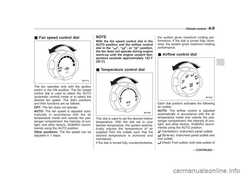
& Fan speed control dialThe fan operates only with the ignition
switch in the ON position. The fan speed
control dial is used to select the AUTO
(automatic control) mode or to select the
desired fan speed. The dial ’s positions
and their functions are as follows.
OFF: The fan does not operate.
AUTO: The fan speed is adjusted auto-
maticallyinaccordancewiththeair
temperature inside and outside the pas-
senger compartment, the intensity of sun-
light, and other factors. SUBARU recom-
mends using the AUTO position.
Other positions: The fan speed can be
adjusted in 7 steps.
NOTEWith the fan speed control dial in the
AUTO position and the airflow control
dial in the “
”, “
”,or “
”position,
the fan does not operate during engine
warm-up until the engine coolant tem-
perature exceeds approximately 1228 F
(50 8C).
& Temperature control dialThis dial is used to set the desired interior
temperature. With the dial set to your
desired temperature, the system automa-
tically adjusts the temperature of air
supplied from the outlets such that the
desired temperature is achieved and
maintained.
If the dial is turned fully counterclockwise, the system gives maximum cooling per-
formance. If the dial is turned fully clock-
wise, the system gives maximum heating
performance.
&
Airflow control dialEach dial position activates the following
air outlets.
AUTO: The airflow control is adjusted
automatically in accordance with the air
temperature inside and outside the pas-
senger compartment, the intensity of sun-
light, and other factors. SUBARU recom-
mends using the AUTO position.
(Ventilation): Instrument panel outlets(Bi-level): Instrument panel outlets and
foot outlets(Heat): Foot outlets, both side outlets of
Climate control
4-9
– CONTINUED –
4
Page 272 of 459
Black plate (276,1)
北米Model "A1110BE-C" EDITED: 2010/ 12/ 17
7-8
Starting and operating
CAUTION
Resultant vehicle damage due to
improper testing is not covered
under the SUBARU Limited War-
ranty and is the responsibility of
the state inspection program or its
contractors or licensees.
The EPA has issued regulations for
inspecting the On-Board Diagnostic
(OBD) system as part of the state emis-
sions inspection. The OBD system is
designed to detect engine and transmis-
sion problems that might cause vehicle
emissions to exceed allowable limits.
These inspections apply to all 1996 model
year and newer passenger cars and light
trucks. Over 30 states plus the District of
Columbia have implemented the OBD
system inspection.
. The inspection of the OBD system
consists of a visual operational check of
the “CHECK ENGINE ”warning light/mal-
function indicator lamp (MIL) and an
examination of the OBD system with an
electronic scan tool while the engine is
running.
. Avehicle
passes the OBD system
inspection if proper illumination of the
“CHECK ENGINE ”warning light/MIL is
observed, there are nostored diagnostic trouble codes, and the OBD system
readiness monitors are complete.
.
A vehicle
fails the OBD inspection if the
“CHECK ENGINE ”warning light/MIL is
not properly operating or there are one or
more diagnostic trouble codes stored in
the vehicle’ s computer with the “CHECK
ENGINE ”warning light/MIL illuminated.
. A state emission inspection may reject
(not pass or fail) a vehicle if the number of
OBD system readiness monitors “Not
Ready” is greater than one. Under this
condition, the vehicle operator should be
instructed to drive his/her vehicle for a few
days to set the monitors and return for an
emission re-inspection.
. Owners of rejected or failing vehicles
should contact their SUBARU Dealer for
service.
Preparing to driveYou should perform the following checks
and adjustments every day before you
start driving.
1. Check that all windows, mirrors, and
lights are clean and unobstructed.
2. Check the appearance and condition
of the tires. Also check tires for proper
inflation.
3. Look under the vehicle for any sign of
leaks.
4. Check that the hood, trunk (4-door)
and rear gate (5-door) are fully closed.
5. Check the adjustment of the seat.
6. Check the adjustment of the inside
and outside mirrors.
7. Fasten your seatbelt. Check that your
passengers have fastened their seatbelts.
8. Check the operation of the warning
and indicator lights when the ignition
switch is turned to the “ON”position.
9. Check the gauges, indicator and warn-
ing lights after starting the engine.NOTEEngine oil, engine coolant, brake fluid,
washer fluid and other fluid levels
should be checked daily, weekly or at
fuel stops.
Page 287 of 459
Black plate (291,1)
北米Model "A1110BE-C" EDITED: 2010/ 12/ 17
“R ” position or vice versa until
the vehicle has completely
stopped. Such shifting may
cause damage to the transmis-
sion.
. When parking the vehicle, first
securely apply the parking brake
and then place the select lever in
the “P ” position. Avoid parking
for a long time with the select
lever in any other position as
doing so could result in a dead
battery.
NOTE. When the engine coolant tempera-
ture is still low, the automatic transmis-
sion will upshift to higher engine
speeds than when the coolant tempera-
ture is sufficiently high in order to
shorten the warm-up time and improve
driveability. The gearshift timing will
automatically shift to the normal timing
after the engine has warmed up.
. Immediately after ATF (automatic
transmission fluid) is replaced, you
may feel that the automatic transmis-
sion operation is somewhat unusual.
This results from invalidation of data
which the on-board computer has
collected and stored in memory to allow the transmission to shift at the
most appropriate times for the current
condition of your vehicle. Optimized
shifting will be restored as the vehicle
continues to be driven for a while.
&
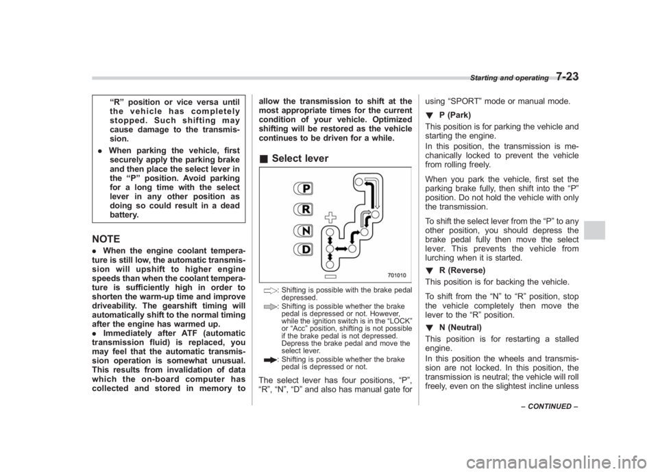
Select lever
: Shifting is possible with the brake pedal
depressed.: Shifting is possible whether the brakepedal is depressed or not. However,
while the ignition switch is in the “LOCK ”
or “Acc ”position, shifting is not possible
if the brake pedal is not depressed.
Depress the brake pedal and move the
select lever.: Shifting is possible whether the brake pedal is depressed or not.
The select lever has four positions, “P”,
“R ”,“N ”, “D ”and also has manual gate for using
“SPORT ”mode or manual mode.
! P (Park)
This position is for parking the vehicle and
starting the engine.
In this position, the transmission is me-
chanically locked to prevent the vehicle
from rolling freely.
When you park the vehicle, first set the
parking brake fully, then shift into the “P ”
position. Do not hold the vehicle with only
the transmission.
To shift the select lever from the “P”to any
other position, you should depress the
brake pedal fully then move the select
lever. This prevents the vehicle from
lurching when it is started.
! R (Reverse)
This position is for backing the vehicle.
To shift from the “N”to “R”position, stop
the vehicle completely then move the
lever to the “R”position.
! N (Neutral)
This position is for restarting a stalled
engine.
In this position the wheels and transmis-
sion are not locked. In this position, the
transmission is neutral; the vehicle will roll
freely, even on the slightest incline unless
Starting and operating
7-23
– CONTINUED –
7